OP-769 16" Three Gun Turrets Part 2 - Personal Page of GENE ...
OP-769 16" Three Gun Turrets Part 2 - Personal Page of GENE ...
OP-769 16" Three Gun Turrets Part 2 - Personal Page of GENE ...
You also want an ePaper? Increase the reach of your titles
YUMPU automatically turns print PDFs into web optimized ePapers that Google loves.
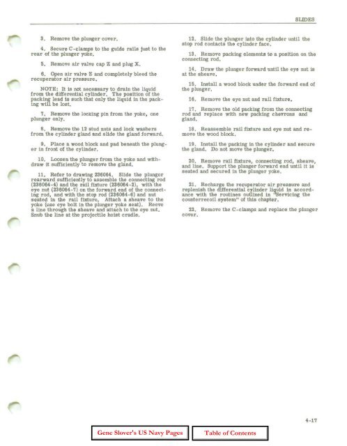
3. Remove the plunger cover.<br />
4. Secure C-clamps to the guide ralls just to the<br />
rear <strong>of</strong> the plunger yoke.<br />
5. Remove air valve cap Z and plug X.<br />
6. Open air valve Z and completely bleed the<br />
recuperator air pressure.<br />
NOTE: It is not necessary to drain the liquid<br />
from the differential cylinder. Tbe position <strong>of</strong> tbe<br />
packing lead is such that only the liquid in the packing<br />
will be lost.<br />
7. Remove the locking pin from the yoke, one<br />
plunge r only.<br />
8. Remove the 12 stud nuts and lock washers<br />
from the cylinder gland and slide the gland forward.<br />
9. Place a wood block and pad beneath the plunger<br />
in front <strong>of</strong> the cylinder.<br />
10. Loosen the plunger from the yoke and withdraw<br />
it sufficiently t o remove the gland.<br />
11. Refer to drawing 236064. Slide the plunger<br />
rearward sufficiently to assemble the connecting rod<br />
(236064-4) and the rail fixture (236064-2), with the<br />
eye nut (236064-7) on the forward end <strong>of</strong> the connecting<br />
rod, and with the stop rod (236064-6) and nut<br />
seated in the rail fixture. Attach a sheave to the<br />
yoke (use eye bolt in the plunger yoke seat). Reeve<br />
a line through the sheave and attach to the eye nut.<br />
Snub the line at the projectile holst cradle.<br />
SLIDES<br />
12. Slide the plunger into the cylinder until the<br />
stop rod contacts the cylinder face.<br />
13. Remove packing elements to a position on the<br />
connecting rod.<br />
14. Draw the plunger forward until the eye nut is<br />
at the sheave.<br />
15. Install a wood block under the forward end <strong>of</strong><br />
the plunger.<br />
16. Remove the eye nut and rail fixture .<br />
17. Remove the old packing from the connecting<br />
rod and replace with new packing chevrons and<br />
gland.<br />
18. Reassemble rail fixture and eye nut and remove<br />
the wood block.<br />
19. Install the packIng in the cylinder and secure<br />
the gland. Do not move the plunger.<br />
20. Remove rail fixture, connecting rod, sheave,<br />
and line. Support the plunger forward end until it is<br />
seated and secured in the plunger yoke.<br />
21. Recharge the recuperator air pressure and<br />
replenish the differential cylinder liquid in accordance<br />
with the routines outlined in "Servlchlg the<br />
counterrecoil system" <strong>of</strong> this chapter.<br />
22. Remove the C-clamps and replace the plunger<br />
cover.<br />
4-17


