OP-769 16" Three Gun Turrets Part 2 - Personal Page of GENE ...
OP-769 16" Three Gun Turrets Part 2 - Personal Page of GENE ...
OP-769 16" Three Gun Turrets Part 2 - Personal Page of GENE ...

Create successful ePaper yourself
Turn your PDF publications into a flip-book with our unique Google optimized e-Paper software.
<strong>OP</strong> <strong>769</strong> 16 I NCH THREE GUN T URRETS<br />
From the B- end, elevation response is s im ultane <br />
ously transmitted through the upper response drive<br />
b racket to the elevation indicator and by a s haft and<br />
a n adjustable coupling to the r eceiver -regulat or. In<br />
t he receiver- regulator, the B -end response rotates<br />
the loading cam and combines with roller path and<br />
eros ion correction input to r otate the stators <strong>of</strong> the<br />
coarse and fine s ynchros. The combined B-end and<br />
s t r oke response inputs pos ition the limit stop valve<br />
V 34 through gear s ector F and the limit stop adjustment<br />
cam.<br />
St r oke response gear. A-end stroke r esponse<br />
is transmItted to the receiver- r egulator from the<br />
neut ral retur n device by a system <strong>of</strong> s hafts and gears,<br />
In the r eceiver-regulator , str oke r es ponse is combined<br />
with B- end response through differential gearing<br />
to position the limit stop valve V34 through gear<br />
s ector F and the limit stop adjust ment ca m. Str oke<br />
res ponse represents gun elevating s peed; it is combined<br />
with B-end (gun position) response to make the<br />
limit stop valve V34 operate sooner at high speeds<br />
than it does at low speeds as the gun approaches its<br />
limit .<br />
Loading cam. The loading cam is rotated by the<br />
B-end elevahon r esponse through a gear t r ain; it is<br />
gear ed dir ectly, without correction input, so that<br />
the gun loading position is always the s ame. The<br />
loading pilot valve V12 is positioned by the loading<br />
cam through a cam follower and c rank a r rangement.<br />
Smooth deceleration and stopping at the load position<br />
are provided by the cam, which is adjustable for gun<br />
loading position.<br />
Limit stop valve V34. T he limit s top valve V34<br />
(fig. 5-9) 1S located m a valve block at t he bottom <strong>of</strong><br />
the r eceiver-regulator valve compartment . P ositioned<br />
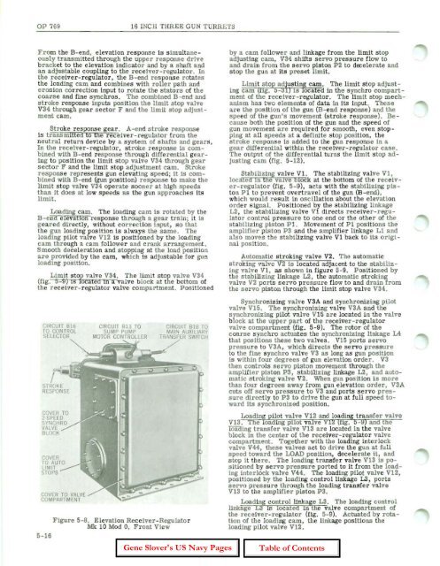
CIRCU IT 816<br />
TO CONTRO L<br />
SELECTOR<br />
STROKE<br />
RESPONSE<br />
COVER TO<br />
;-SPEED<br />
SYNCHRO<br />
VALVE<br />
BLOCK<br />
COVER<br />
TO AUTO<br />
LIMIT<br />
ST<strong>OP</strong>S<br />
COVER TO VALVE<br />
COMPARTMENT<br />
CIRC U IT B 13 TO<br />
SUMP PUMP<br />
MOTOR CONTROLLER<br />
CIRCU IT BIB 10<br />
MAIN AU XILIARY<br />
TRANSFER SWITCH<br />
Figure 5-8. E levation Receiver-Regulator<br />
Mk 10 Mod 0, Front View<br />
5-16<br />
by a ca m follower and linkage from the limit stop<br />
adjusting cam, V 34 s hifts servo pressure flow to<br />
and drain from the ser vo piston P2 to dreelerate and<br />
stop t he gun at its pr eset limit.<br />
Limit st op adjusting cam. The limit stop adjust <br />
ing cam (fig. 5-31) IS locatea in the s ynchro compartment<br />
<strong>of</strong> the r eceiver-regulator. T he limit stop m echanism<br />
has two elements <strong>of</strong> data in its input. These<br />
a r e the position <strong>of</strong> t he gun (B-end response) and the<br />
speed <strong>of</strong> the gun's movement (stroke response). Because<br />
both the pOSition <strong>of</strong> the gun and the speed <strong>of</strong><br />
gun movement are r equired for s mooth, even stopping<br />
at all speeds at a definite stop pOSition, the<br />
stroke response is added to t he gun response in a<br />
gear differential within the r eceiver -regulator case.<br />
The output <strong>of</strong> the differential turns the limit stop adjusting<br />
cam (fig. 5- 12).<br />
Stabilizing valve Vl. The stabilizing valve Vi,<br />
located m t he valve block at the bottom <strong>of</strong> the receiv <br />
er-r egulat or (fig . 5- 9), acts with the stabilizing piston<br />
P 1 to prevent overtravel <strong>of</strong> the gun (B - end) ,<br />
which would r esult in os cillation about the elevation<br />
order signal. P ositioned by the stabilizing linkage<br />
L2 , the stabiliZing valve V1 directs r eceiver-regulat<br />
or control pressur e to one end or the othe r <strong>of</strong> the<br />
stabiliz ing pis ton P l. Movement <strong>of</strong> Pl pos itions the<br />
amplifier piston P3 and the amplifier linkage L1 and<br />
also moves the stabilizing valve Vl back to its original<br />
position.<br />
Aut omatic str oking valve V2. The automat ic<br />
str oking valve V2 is located adjacent to the stabiliz <br />
ing valve V1, as s hown in figure 5- 9. P os itioned by<br />
the stabilizing linkage L2, the automat ic str oking<br />
valve V2 ports s ervo pressure flow to and drain from<br />
the ser vo piston through the limit stop valve V34 .<br />
Synchronizing valve V3A and s ynchr onizing pilot<br />
valve V15. The synchr onizing valve V3A and the<br />
synchronizing pilot valve V15 ar e located in the valve<br />
block at the upper part <strong>of</strong> the r eceiver-regulator<br />
valve compartment (fig. 5-9). The r otor <strong>of</strong> t he<br />
coarse s ynchr o actuates the synchronizing linkage L4<br />
that positions these two valves. V 15 ports servo<br />
pressure to V3A, which dir ects the servo pr essure<br />
t o the fine s ynchro valve V3 as long as gun position<br />
is within four degrees <strong>of</strong> gun elevation orde r. V3<br />
then controls servo piston movement through the<br />
amplifier pist on P3, stabilizing linkage L2, and automatic<br />
s t r oking valve V 2. When gun position is more<br />
than four degrees away from gun elevation order, V3 A<br />
cuts <strong>of</strong>f ser vo pressur e t o V3 and ports servo pressure<br />
dir ectly to P3 to drive the gun at full speed toward<br />
its synchronized position.<br />
Loading pilot valve V 12 and loading transfer valve<br />
V13 . The loadIng pilot valve V 12 (fig . 5 - 9) and the<br />
wading transfer valve Vl3 are located in the valve<br />
block in the cente r <strong>of</strong> the receiver - regulator valve<br />
compartm ent. Together with the loading interlock<br />
valve V44, these valves act to drive the gun at fu ll<br />
speed t oward the LOAD position, deceler ate it, and<br />
stop it ther e . The loading t r ansfer valve V 13 is pos<br />
itioned by s ervo pressur e ported to it fr om the loading<br />
interlock valve V44. The loading pilot valve V12,<br />
pos itioned by the loading control linkage 1.3 , por ts<br />
s ervo pr essur e through the loading transfer valve<br />
V13 to the amplifie r piston P3.<br />
Loading control linkage L3. The loading contr ol<br />
linkage L3 is located in the valve compartment <strong>of</strong><br />
the receiver- regulat or (fig. 5-9). Actuated by rotation<br />
<strong>of</strong> the loading cam, the linkage positions the<br />
loading pilot valve V12 .