rupture disc assemblies - Carlyle Certified Refrigeration Partners
rupture disc assemblies - Carlyle Certified Refrigeration Partners
rupture disc assemblies - Carlyle Certified Refrigeration Partners

You also want an ePaper? Increase the reach of your titles
YUMPU automatically turns print PDFs into web optimized ePapers that Google loves.
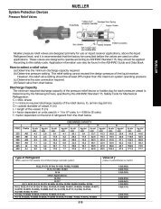
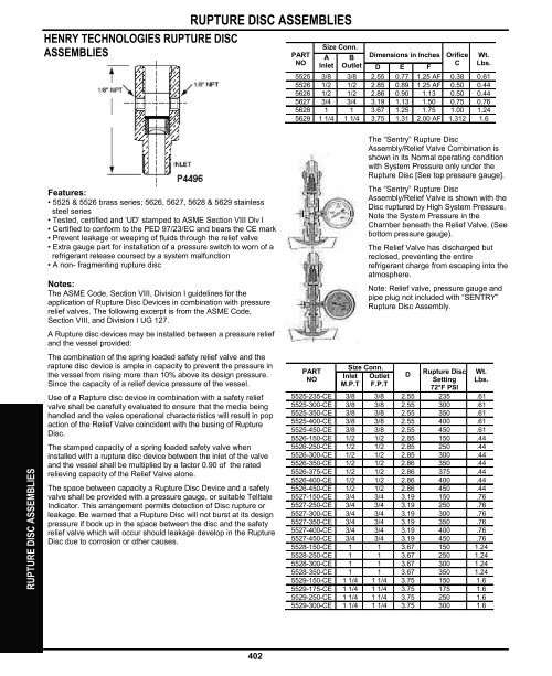
RUPTURE DISC ASSEMBLIES<br />
HENRY TECHNOLOGIES RUPTURE DISC<br />
ASSEMBLIES<br />
Features:<br />
• 5525 & 5526 brass series; 5626, 5627, 5628 & 5629 stainless<br />
steel series<br />
• Tested, certified and ‘UD’ stamped to ASME Section VIII Div I<br />
• <strong>Certified</strong> to conform to the PED 97/23/EC and bears the CE mark<br />
• Prevent leakage or weeping of fluids through the relief valve<br />
• Extra gauge part for installation of a pressure switch to worn of a<br />
refrigerant release coursed by a system malfunction<br />
• A non- fragmenting <strong>rupture</strong> <strong>disc</strong><br />
Notes:<br />
The ASME Code, Section VIII, Division I guidelines for the<br />
application of Rupture Disc Devices in combination with pressure<br />
relief valves. The following excerpt is from the ASME Code,<br />
Section VIII, and Division I UG 127.<br />
A Rupture <strong>disc</strong> devices may be installed between a pressure relief<br />
and the vessel provided:<br />
The combination of the spring loaded safety relief valve and the<br />
rapture <strong>disc</strong> device is ample in capacity to prevent the pressure in<br />
the vessel from rising more than 10% above its design pressure.<br />
Since the capacity of a relief device pressure of the vessel.<br />
Use of a Rapture <strong>disc</strong> device in combination with a safety relief<br />
valve shall be carefully evaluated to ensure that the media being<br />
handled and the vales operational characteristics will result in pop<br />
action of the Relief Valve coincident with the busing of Rupture<br />
Disc.<br />
The stamped capacity of a spring loaded safety valve when<br />
installed with a <strong>rupture</strong> <strong>disc</strong> device between the inlet of the valve<br />
and the vessel shall be multiplied by a factor 0.90 of the rated<br />
relieving capacity of the Relief Valve alone.<br />
RUPTURE DISC ASSEMBLIES<br />
The space between capacity a Rupture Disc Device and a safety<br />
valve shall be provided with a pressure gauge, or suitable Telltale<br />
Indicator. This arrangement permits detection of Disc <strong>rupture</strong> or<br />
leakage. Be warned that a Rupture Disc will not burst at its design<br />
pressure if bock up in the space between the <strong>disc</strong> and the safety<br />
relief valve which will occur should leakage develop in the Rupture<br />
Disc due to corrosion or other causes.<br />
402<br />
Size Conn.<br />
PART<br />
NO<br />
A<br />
Inlet<br />
B<br />
Outlet<br />
Dimensions in Inches<br />
D E F<br />
Orifice<br />
C<br />
Wt.<br />
Lbs.<br />
5525 3/8 3/8 2.55 0.77 1.25 AF 0.38 0.61<br />
5526 1/2 1/2 2.85 0.89 1.25 AF 0.50 0.44<br />
5626 1/2 1/2 2.86 0.90 1.13 0.50 0.44<br />
5627 3/4 3/4 3.19 1.13 1.50 0.75 0.76<br />
5628 1 1 3.67 1.25 1.75 1.00 1.24<br />
5629 1 1/4 1 1/4 3.75 1.31 2.00 AF 1.312 1.6<br />
PART<br />
NO<br />
Size Conn.<br />
Inlet<br />
M.P.T<br />
The “Sentry” Rupture Disc<br />
Assembly/Relief Valve Combination is<br />
shown in its Normal operating condition<br />
with System Pressure only under the<br />
Rupture Disc [See top pressure gauge].<br />
The “Sentry” Rupture Disc<br />
Assembly/Relief Valve is shown with the<br />
Disc <strong>rupture</strong>d by High System Pressure.<br />
Note the System Pressure in the<br />
Chamber beneath the Relief Valve. (See<br />
bottom pressure gauge).<br />
The Relief Valve has <strong>disc</strong>harged but<br />
reclosed, preventing the entire<br />
refrigerant charge from escaping into the<br />
atmosphere.<br />
Note: Relief valve, pressure gauge and<br />
pipe plug not included with “SENTRY”<br />
Rupture Disc Assembly.<br />
Outlet<br />
F.P.T<br />
D<br />
Rupture Disc<br />
Setting<br />
72°F PSI<br />
Wt.<br />
Lbs.<br />
5525-235-CE 3/8 3/8 2.55 235 .61<br />
5525-300-CE 3/8 3/8 2.55 300 .61<br />
5525-350-CE 3/8 3/8 2.55 350 .61<br />
5525-400-CE 3/8 3/8 2.55 400 .61<br />
5525-450-CE 3/8 3/8 2.55 450 .61<br />
5526-150-CE 1/2 1/2 2.85 150 .44<br />
5526-250-CE 1/2 1/2 2.85 250 .44<br />
5526-300-CE 1/2 1/2 2.85 300 .44<br />
5526-350-CE 1/2 1/2 2.86 350 .44<br />
5526-375-CE 1/2 1/2 2.86 375 .44<br />
5526-400-CE 1/2 1/2 2.86 400 .44<br />
5526-450-CE 1/2 1/2 2.86 450 .44<br />
5527-150-CE 3/4 3/4 3.19 150 .76<br />
5527-250-CE 3/4 3/4 3.19 250 .76<br />
5527-300-CE 3/4 3/4 3.19 300 .76<br />
5527-350-CE 3/4 3/4 3.19 350 .76<br />
5527-400-CE 3/4 3/4 3.19 400 .76<br />
5527-450-CE 3/4 3/4 3.19 450 .76<br />
5528-150-CE 1 1 3.67 150 1.24<br />
5528-250-CE 1 1 3.67 250 1.24<br />
5528-300-CE 1 1 3.67 300 1.24<br />
5528-350-CE 1 1 3.67 350 1.24<br />
5529-150-CE 1 1/4 1 1/4 3.75 150 1.6<br />
5529-175-CE 1 1/4 1 1/4 3.75 175 1.6<br />
5529-250-CE 1 1/4 1 1/4 3.75 250 1.6<br />
5529-300-CE 1 1/4 1 1/4 3.75 300 1.6
HENRY TECHNOLOGIES RUPTURE ASSEMBLY PRESSURE SWITCH<br />
Pressure Switch SW57<br />
Features:<br />
Pressure Switch SW58<br />
RUPTURE ASSEMBLY PRESSURE SWITCHES/INDICATORS<br />
• Type: Direct action blade contact<br />
• Contacts: Silver alloy, gold plated<br />
• Set point: Factory set and sealed<br />
• Pressure Setting: 5 PSI<br />
• Switch Burst Pressure: 750 PSI<br />
• Ratings: 4 AMP- 24 VAC<br />
• Diaphragm: Teflon<br />
• Temperature Range: -40°F to +250°F<br />
• Connector: 1/8-27 NPT male thread<br />
• Terminals: Metri-Pack. ¼” blade<br />
• Circuitry: Normally opened<br />
• Base: Steel<br />
• Cover: Glass reinforced polyester<br />
Furnished with Metri-Pack Connector<br />
and 10 ft. of wire<br />
Features:<br />
• Type: Single pole double throw<br />
• Contacts: General Purpose<br />
• Set Point: Factory set and sealed<br />
• Pressure setting: 5 PSI<br />
• Switch Burst Pressure: 9000 PSI<br />
• Ratings: 5AMP-12/24 VDC and<br />
120/240 VAC<br />
• Diaphragm: Neoprene<br />
Notes:<br />
The addition of the Pressure<br />
Switch provides inexpensive<br />
means of providing an electrical<br />
signal to warn of a refrigerant<br />
please caused by a system<br />
modification. An extra gauge part<br />
is provided on our Sentry Rupture<br />
Disc Assembly for the Pressure<br />
Switch.<br />
• Temperature Range: -40°F to<br />
+176°F<br />
• Connector: 1/8-27 NPT male thread<br />
• Terminals: ¼” blade<br />
• Circuitry: Normally opened<br />
• Base: Stainless-steel<br />
• Cover: Glass reinforced polyester<br />
• Furnished with 10 ft. of wire<br />
HENRY TECHNOLOGIES RUPTURE ASSEMBLY PRESSURE INDICATOR<br />
• Dial: 1-3/8-in. (35 mm), White Aluminum Dial with Red Marking<br />
• Dial: Maximum Working Pressure: 600 PSI<br />
• Case: AISI 304 Stainless Steel<br />
• Lens: Plexiglass, Watertight<br />
• Pointer: AISI 304 Stainless Steel<br />
• Socket: AISI 304 Stainless Steel<br />
• Ambient Temperature: –40° F/+150° F (–40° C+65° C)<br />
NOTES: The Pressure Indicator (Item A) can be used with our Sentry<br />
Rupture Disc Assembly (Item B), which helps prevent leakage of both<br />
halocarbon and ammonia refrigerants by indicating whether the relief valve<br />
had <strong>disc</strong>harged. The Sentry Rupture Disc Assembly, as required by<br />
ANSI/ASME Code, provides a chamber between the <strong>rupture</strong> <strong>disc</strong> and the<br />
relief valve, and a connection to install the new pressure indicator. This<br />
arrangement permits<br />
a positive indication that the <strong>disc</strong> has <strong>rupture</strong>d and the relief valve has<br />
<strong>disc</strong>harged. The “Sentry” Rupture Disc Assembly/Relief Valve Combination<br />
is shown in its Normal operating condition with System Pressure only under<br />
the Rupture Disc. (See first pressure gauge.)<br />
NOTE: Relief valve, pressure gauge and pipe plug not included with “Sentry”<br />
Rupture Disc Assembly.<br />
403<br />
PART<br />
SIZE<br />
NO<br />
CONNECTION<br />
G15 1/8-in. MPT, Back<br />
RUPTURE ASSEMBLY PRESSURE SWITCHES/INDICATORS
RUPTURE ASSEMBLY PRESSURE SWITCHES/INDICATORS<br />
RUPTURE ASSEMBLY PRESSURE SWITCHES/INDICATORS<br />
HENRY TECHNOLOGIES TRANSDUCER VALVE<br />
• ForgedBrass<br />
• Temperature Rating: –20° F (–29° C) to +300° F (+149° C)<br />
• Maximum Working Pressure: 500 PSI (35 kg/cm2)<br />
• Connector: 1/4-in. Flare Access with Schrader Core<br />
• Provides Access to Systems and Mounting of a Transducer to<br />
Monitor Systems Performance<br />
• Provides Schrader Valve Port for Checking Transducer<br />
Output with a Pressure Gauge<br />
• Provides Isolation from System for Replacement of Transducer<br />
• Suitable for Refrigerants and Other Industrial Fluids<br />
Non-Corrosive to Brass and Steel<br />
SIZE CONN (in) DIMENSIONS (in)<br />
PART NO Bottom Side A B C D WT(lb)<br />
9290 1/4 MPT 1/8 FPT-1/4 FL 2.38 1.19 1.56 4.16 .52<br />
404