
You also want an ePaper? Increase the reach of your titles
YUMPU automatically turns print PDFs into web optimized ePapers that Google loves.
System Protection Devices<br />
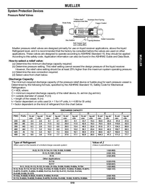
Pressure Relief Valves<br />
Mueller pressure relief valves are designed primarily for use on liquid receiver applications, above the liquid<br />
Refrigerant level, and it is recommended that the factory be consulted before the valves are used on other<br />
applications. These valves are designed to operate according to ASHRAE Standard 15, they should be applied<br />
According to this safety code. Application information can also be found in the ASHRAE Guide and Data Book.<br />
How to select a relief valve:<br />
(a) Determine the minimum discharge capacity required.<br />
(b) Determine pressure setting. This relief setting cannot exceed the design pressure of the liquid receiver.<br />
However, the relief valve setting should be at least 25% higher than the maximum system operating pressure.<br />
(c) Determine the size connection required.<br />
(d) Select valve from chart below.<br />
Discharge Capacity<br />
The minimum required discharge capacity of the pressure relief device or fusible plug for each pressure vessel is<br />
Determined by the following formula, specified by the ASHRAE Standard 15, Safety Code for Mechanical<br />
Refrigeration:<br />
C = kfDL where:<br />
C = minimum required discharge capacity of the relief device, lb. air/min (kg air/min)<br />
D = outside diameter of vessel, ft (m)<br />
L = length of the vessel, ft (m)<br />
k = factor dependent on units used (k = 1 for l-P units, k = 4.88 for Sl units)<br />
f = factor dependent on the kind of refrigerant from the chart below<br />
DISCHARGE CAPACITY<br />
A B C D E F<br />
PSIG Prefix lb air/ kg air/ lb air/ kg air/ lb air/ kg air/ lb air/ kg air/ lb air/ kg air/ lb air/ kg air/<br />
min min min min min min min min min min min min<br />
235 AD 4.3 2.0 9.1 4.1 20.1 9.1 33.7 15.3 55.9 25.4 91.8 41.6<br />
300 AE 5.4 2.4 11.5 5.2 25.4 11.5 42.5 19.3 70.5 32.0 115.8 52.5<br />
350 AG 6.3 2.9 13.3 6.0 29.5 13.4 49.3 22.4 81.8 37.1 134.3 60.9<br />
400 AH 7.1 3.2 15.2 6.9 33.5 15.2 56.1 25.4 93.0 42.2 152.7 69.3<br />
425 AI 7.6 3.4 16.1 7.3 35.6 16.1 59.5 27.0 98.6 44.7 162.0 73.5<br />
450 AJ 8.0 3.6 17.0 7.7 37.6 17.1 62.9 28.5 104.3 47.3 171.2 77.7<br />
Type of Refrigerant<br />
When used on the lowside of a limited-charge cascade system<br />
<strong>MUELLER</strong><br />
Value of ƒ<br />
(Value in parentheses is metric)<br />
R-23, R-170, R-744, R-1150, R-508, R-508B 1.0(0.082)<br />
R-13, R-13B1, R-503 2.0(0.163)<br />
R-14<br />
Other Applications:<br />
2.5(0.203)<br />
R-718 0.2(0.016)<br />
R-717 0.5(0.041)<br />
R-11, R-32, R-113, R-123, R-142b ,R-152a, R-290, R-600, R-600a, R-764 1.0(0.082)<br />
R-12, R-22, R-114, R-124, R-134a, R-410A, R-104B, R-401C, R-405A, R-406A, R-407C,<br />
R-407D, R-407E, R-409A, R-409B, R-411A, R-411B, R-411C, R-412A, R-414A,<br />
R-414B, R-500, R-1270<br />
1.6(0.131)<br />
R-143a, R-402B, R-403A, R-407A, R-408A, R-413A 2.0(0.163)<br />
R-115, R-402A, R-403B, R-404A, R-407B, R-410A, R-410B, R-502, R-507A, R-509A 2.5(0.203)<br />
519<br />
<strong>MUELLER</strong>
<strong>MUELLER</strong><br />
System Protection Devices<br />
Pressure Relief Valves<br />
Straight Thru - NPTFE Inlet to Flare<br />
Angle - NPTFE to Flare<br />
Atmospheric - NPTFE Inlet<br />
Straight Thru - NPTFE Inlet to NPTFI Outlet<br />
Straight Thru-Straight Thread Inlet to NPTFI Outlet<br />
Prefixes for standard settings are:<br />
<strong>MUELLER</strong><br />
C<br />
ASME VALVE INLET (A) (in) OUTLET (B) (in) (in) (cm) DISCHARGE<br />
TABLE<br />
(lb) (kg)<br />
A 15501 1⁄4 3⁄8 2-21/32 6.75 A 0.19 0.09<br />
A 15502 3⁄8 3⁄8 2-13/16 7.14 B 0.33 0.15<br />
A 15503 3⁄8 1⁄2 3 7.62 B 0.36 0.16<br />
A 15504 1⁄2 5⁄8 4-3/16 10.64 C 0.84 0.38<br />
B 33752 1⁄4 3⁄8 2-13/16 7.14 B 0.32 0.14<br />
B 33753 1⁄4 1⁄2 3 7.62 B NA NA<br />
C D WT/ EA<br />
ASME VALVE INLET (A) (in) OUTLET (B) (in) (in) (cm) (in) (cm) DISCHARGE<br />
TABLE<br />
(lb) (kg)<br />
B 33746 1⁄4 3⁄8 2-3/8 6.03 1-1/8 2.86 B 0.30 0.14<br />
B 33754 1⁄4 1⁄2 2-7/16 6.19 1-5/16 3.33 B NA NA<br />
A 15512 3⁄8 3⁄8 2-3/8 6.03 1-3/8 3.49 B 0.36 0.16<br />
A 15513 3⁄8 1⁄2 2-3/8 6.03 1-11/32 3.41 B 0.38 0.17<br />
A 15514 1⁄2 5⁄8 4-3/32 10.40 1-9/16 3.97 C 0.98 0.45<br />
C<br />
ASME VALVE INLET (A) (in) B (in) (in) (cm) DISCHARGE<br />
TABLE<br />
(lb) (kg)<br />
A 15508 1⁄8 1-7/8 3⁄4 1.91 A 0.12 0.05<br />
A 15509 1⁄4 2 3⁄4 1.91 A 0.13 0.06<br />
A 17430 3⁄8 2-1/8 1 2.54 B 0.24 0.11<br />
B 33755 1⁄4 2-1/8 1 2.54 B NA NA<br />
C<br />
ASME VALVE INLET (A) (in) OUTLET (B) (in) (in) (cm) DISCHARGE<br />
TABLE<br />
(lb) (kg)<br />
A 17840 1 1 4-9/16 11.59 E 1.95 0.88<br />
A 17834 1-1/4 1-1/4 5 12.70 F 2.00 0.91<br />
A 15506 3⁄4 3⁄4 5 12.70 D 1.49 0.68<br />
C<br />
ASME VALVE INLET (A) (in) OUTLET (B) (in) (in) (cm) DISCHARGE<br />
TABLE<br />
(lb) (kg)<br />
B 34444 7⁄8 -14 UNF 2A 3⁄4 5 12.70 D 1.53 0.69<br />
B 34519 1-5/16 -12UNF2A 1 4-3/8 11.11 E 1.37 0.62<br />
B 34580 1-5/8 -12UNF-2A 1-1/4 5 12.70 F 2.00 0.91<br />
AD/BD= 235 psig. AH/BH = 400 psig.<br />
AE/BE = 300 psig. AI/BI = 425 psig.<br />
AG/BG = 350 psig. AJ/BJ = 450 psig.<br />
For valves furnished at non-standard settings, use part numbers as listed in specification charts<br />
and indicate exact pressure setting.<br />
520