

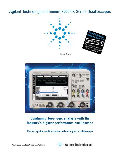
Agilent Technologies Infiniium 90000 X-Series Oscilloscopes
Agilent Technologies Infiniium 90000 X-Series Oscilloscopes
Agilent Technologies Infiniium 90000 X-Series Oscilloscopes

You also want an ePaper? Increase the reach of your titles
YUMPU automatically turns print PDFs into web optimized ePapers that Google loves.
<strong>Agilent</strong> <strong>Technologies</strong> <strong>Infiniium</strong> <strong>90000</strong> X-<strong>Series</strong> <strong>Oscilloscopes</strong><br />
Data Sheet<br />
Combining deep logic analysis with the<br />
industry’s highest performance oscilloscope<br />
Featuring the world’s fastest mixed signal oscilloscope
Engineered for 33 GHz true analog bandwidth that delivers:<br />
Need bandwidth?<br />
When you’re deploying leading edge high-speed serial bus<br />
designs like FibreChannel, SAS 12 G, or 10 Gb Ethernet<br />
KR, jitter matters and picoseconds count. When you’re<br />
doing spectral analysis of wide-bandwidth RF signals or<br />
investigating transient phenomena, bandwidth is critical.<br />
You need the most accurate real-time oscilloscope you can<br />
get. <strong>Agilent</strong> <strong>Infiniium</strong> <strong>90000</strong> X-<strong>Series</strong> scopes are engineered<br />
for 33 GHz true analog bandwidth that delivers:<br />
• The industry’s highest real-time scope measurement accuracy<br />
• The industry’s only 30 GHz oscilloscope probing system<br />
• The industry’s fastest logic analysis on an oscilloscope<br />
(16 channels at up to 50 ps timing resolution)<br />
33 GHz and still improving<br />
The industry experts have spoken, and the <strong>90000</strong> X-<strong>Series</strong> is<br />
one of the most award-winning oscilloscopes in the history<br />
of the oscilloscope industry. With <strong>Agilent</strong>’s <strong>90000</strong> X-<strong>Series</strong><br />
oscilloscope, you get up to 33 GHz of real-time bandwidth<br />
and the best measurement accuracy.<br />
Even with all of the <strong>90000</strong> X-<strong>Series</strong>’ success, <strong>Agilent</strong>’s<br />
software and hardware teams still continue to improve its<br />
accuracy and capability. The <strong>90000</strong> X-<strong>Series</strong> now features<br />
a more accurate calibration, PrecisionProbe software,<br />
InfiniiView software, and EZJIT Complete; making it the<br />
go-to tool for not only your compliance needs, but also your<br />
design and validation needs.<br />
Need more than just a regular oscilloscope?<br />
As part of its continual improvement, <strong>90000</strong> X-<strong>Series</strong> now<br />
has 16 digital channels with time resolution as fast as 50 ps.<br />
The mixed signal oscilloscope is the ideal tool for debugging<br />
tough memory challenges with unique triggering specific to<br />
memory technologies.<br />
2<br />
Analog bandwidth Sample rate Max Memory<br />
Model number 2 channel 4 channel 2 channel 4 channel depth 4 channel<br />
DSAX93204A 33 GHz 16 GHz 80 GSa/s 40 GSa/s 2 Gpts<br />
DSOX93204A 33 GHz 16 GHz 80 GSa/s 40 GSa/s 2 Gpts<br />
DSAX92804A 28 GHz 16 GHz 80 GSa/s 40 GSa/s 2 Gpts<br />
DSOX92804A 28 GHz 16 GHz 80 GSa/s 40 GSa/s 2 Gpts<br />
DSAX92504A 25 GHz 16 GHz 80 GSa/s 40 GSa/s 2 Gpts<br />
DSOX92504A 25 GHz 16 GHz 80 GSa/s 40 GSa/s 2 Gpts<br />
DSAX92004A 20 GHz 16 GHz 80 GSa/s 40 GSa/s 2 Gpts<br />
DSOX92004A 20 GHz 16 GHz 80 GSa/s 40 GSa/s 2 Gpts<br />
DSAX91604A 16 GHz 16 GHz 80 GSa/s 40 GSa/s 2 Gpts<br />
DSOX91604A 16 GHz 16 GHz 80 GSa/s 40 GSa/s 2 Gpts<br />
DSAX91304A 13 GHz 13 GHz 80 GSa/s 40 GSa/s 2 Gpts<br />
DSOX91304A 13 GHz 13 GHz 80 GSa/s 40 GSa/s 2 Gpts<br />
Custom front end technology requiring over five years of design<br />
effort yields the fastest real-time oscilloscope hardware available<br />
today.<br />
BW Upgradeable<br />
Buy the performance<br />
you need today<br />
knowing you have the<br />
headroom you need<br />
for tomorrow with<br />
bandwidth upgradability<br />
to 33 GHz
Engineered for 33 GHz true analog bandwidth that delivers:<br />
Industry’s first and only 30 GHz oscilloscope probing<br />
system.<br />
No matter how much bandwidth your scope has, if<br />
your probes can’t match the scope’s bandwidth, your<br />
measurements are compromised. The <strong>Agilent</strong> <strong>Infiniium</strong> <strong>90000</strong><br />
X-<strong>Series</strong> scopes offer probing solutions that are up to the<br />
tough challenges today’s high-speed signal data rates with<br />
the following:<br />
• InfiniiMax III high frequency probes with automatic<br />
AC calibration (PrecisionProbe)<br />
• Fully-integrated probe amplifier s-parameter<br />
correction<br />
• The industry’s first bandwidth-upgradable probe<br />
amplifier<br />
Easily isolate signals of interest with zone qualified view<br />
using InfiniiScan software triggering, just one of more than<br />
40 application-specific software options.<br />
The industry’s highest real-time scope measurement<br />
accuracy.<br />
When you’re designing with faster signals, shrinking<br />
eyes and tighter jitter budgets errors introduced by your<br />
oscilloscope can seriously impact your design margins. The<br />
<strong>Agilent</strong> <strong>Infiniium</strong> <strong>90000</strong> X-<strong>Series</strong> scopes deliver the highest<br />
measurement accuracy available by offering the following<br />
characteristics:<br />
• True analog bandwidth to 33 GHz<br />
• Lowest oscilloscope noise floor (2.10 mV at 50 mV / div,<br />
33 GHz)<br />
• Lowest jitter measurement floor (100 fs)<br />
Having the most accurate analog bandwidth and lowest<br />
noise floor available means better spectral analysis of<br />
transients and wide-bandwidth RF signals.<br />
The industry’s most comprehensive applicationspecific<br />
measurement software.<br />
When time is of the essence, you need tools that can speed<br />
true understanding of your signal activity. From serial bus<br />
debug and compliance testing to jitter measurements to<br />
sophisticated triggering capability, <strong>Agilent</strong> stays on top of<br />
the test standards and your requirements by working to<br />
ensure that you get accurate results more quickly.<br />
The <strong>Agilent</strong> <strong>Infiniium</strong> <strong>90000</strong> X-<strong>Series</strong> scopes offer the following:<br />
• The broadest range of jitter, triggering, analysis and<br />
display tools<br />
• Pre-built compliance testing software based on the<br />
expertise of our engineers on the standards committees<br />
• Support for emerging technologies including<br />
FibreChannel, SAS 12G, or MIPI-MPhy<br />
3
Engineered for 33 GHz true analog bandwidth that now combines deep<br />
logic analysis with the industry’s highest performance oscilloscope:<br />
33 GHz true analog bandwidth of the<br />
oscilloscope and 80 GSa/s sample rate<br />
provides ultra-low noise.<br />
See your signal more clearly with a 12.1-inch<br />
XGA (1024 x 768) high-resolution color touch<br />
screen display.<br />
Identify anomalies easily with a 256-level<br />
intensity-graded or color-graded persistence<br />
display that provides a three dimensional view<br />
of your signals.<br />
Remote access through 10/100/1000 BaseT<br />
LAN interface with web-enabled connectivity<br />
uses ultra-responsive Ultra VNC.<br />
GPIB and LAN provide remote measurements.<br />
Optional <strong>Infiniium</strong> application remote program<br />
interface allows application/compliance<br />
software automation. LXI class C compliant.<br />
MATLAB support.<br />
An additional four USB 2.0 host ports and a<br />
USB 2.0 device port on the back panel. Perfect<br />
for extra connectivity including an optical<br />
drive. A USB 2.0 device port lets you control<br />
the scope and transfer data via a USB 2.0 480-<br />
Mbpts connection.<br />
Calibration edge with a rise time of less<br />
than 15 ps enables TDT calibration with<br />
PrecisionProbe software.<br />
4<br />
Capture your longest signal with up to<br />
25 ms data using 2 Gpt of acquisition<br />
memory at 80 GSa/s.<br />
Optional x4 PCIExpress slot speeds up offload times by<br />
a factor of 5, using socket drivers. Use this option (823)<br />
for faster deep offloads of the waveforms.
Featuring bandwidths from 13 to 33 GHz<br />
10 MHz reference clock can be input to<br />
or output from the scope to allow precise<br />
timebase synchronization with more than<br />
one oscilloscope, RF instruments or logic<br />
analyzers.<br />
Threaded RF connectors ensure the most reliable signal integrity<br />
for high-performance instruments. The AutoProbe II interface<br />
combines the tried-and-true, robust 3.5 mm threaded RF connector<br />
of <strong>Agilent</strong> sampling scopes with a convenient automatic torque<br />
mechanism (clutch) that ensures a consistent 8 in. lbs. connection<br />
is made without the hassles of a torque wrench.<br />
Dedicated single acquisition button provides<br />
better control to capture a unique event.<br />
Customizable multipurpose key gives you any<br />
five automated measurements with a push<br />
of a button. You can also configure this key<br />
to execute a script, print/save screen shots,<br />
save waveforms or load a favorite setup.<br />
Measure section, including a toggling marker<br />
button and a dedicated marker knob, provides<br />
quick access to your marker control.<br />
Quick access to fine/vernier control by<br />
pressing the horizontal and vertical sensitivity<br />
knobs.<br />
Increase your productivity with a familiar<br />
<strong>Infiniium</strong> graphical user interface, including<br />
your favorite drag-and-drop measurement<br />
icons. <strong>Infiniium</strong>’s analog-like front panel<br />
has a full set of controls color-coded to the<br />
waveforms and measurements, making your<br />
tasks simple.<br />
Three front panel USB 2.0 host ports match<br />
your USB keyboard, mouse, and USB memory<br />
drive connection for saving setup and data<br />
files and screen shots.<br />
Removable hard disk drive option is available.<br />
It features a solid state drive for added data<br />
security and speed.<br />
5
Engineered for 33 GHz true analog bandwidth that delivers:<br />
The Oscilloscope: highest real-time scope measurement accuracy<br />
Whether you’re deploying emerging high speed bus<br />
technology, identifying spectral content of wide-bandwidth<br />
RF signals, or analyzing transient physical phenomena, you<br />
need the truest representation of your signals under test.<br />
<strong>Agilent</strong> invested in leading edge technology to bring you<br />
the highest real-time oscilloscope measurement accuracy<br />
available today.<br />
Low noise floor<br />
One of the keys to measurement accuracy at high<br />
bandwidths is minimizing the noise generated<br />
by the oscilloscope itself. <strong>Agilent</strong> utilizes a<br />
proprietary Indium Phosphide (InP) integrated<br />
circuit process in the design of the <strong>Infiniium</strong> <strong>90000</strong><br />
X-<strong>Series</strong> oscilloscopes because other oscilloscope<br />
techniques just can’t deliver the necessary<br />
combination of high-bandwidth and low noise. Not<br />
only does that mean you’re purchasing the best<br />
tool today, but it also means you can count on<br />
technology leadership from <strong>Agilent</strong> in the future.<br />
6<br />
Custom integrated circuits using a proprietary Indium<br />
Phosphide (InP) process and breakthrough packaging<br />
technology enable industry-leading performance, including<br />
the:<br />
Up to 33 GHz of true analog bandwidth<br />
Lowest oscilloscope noise floor<br />
Lowest oscilloscope jitter measurement floor<br />
True-analog bandwidth- 33 GHz<br />
The engineering of a high-performance real-time oscilloscope<br />
front end requires designing pre-amplifiers, triggering<br />
capability, and sampling technology, then seamlessly tying<br />
them together. Using fine line microcircuit processes and<br />
relying extensively on years of experience with RF design,<br />
<strong>Agilent</strong> developed the front end multi-chip modules shown<br />
here for the <strong>Infiniium</strong> <strong>90000</strong> X-<strong>Series</strong> oscilloscopes. Packaging<br />
technology provides excellent high-frequency electrical<br />
properties along with superior heat dissipation. It is a key<br />
enabling technology block in <strong>Agilent</strong>’s <strong>90000</strong> X-<strong>Series</strong>’ high<br />
measurement accuracy.
Jitter measurement floor of less than 100 fs<br />
Better calibration improves spectral purity<br />
<strong>Agilent</strong> oscilloscopes are constantly improving<br />
their measurement accuracy. The latest<br />
innovation is a new, improved calibration routine<br />
that better aligns the sample points of the<br />
analog to digital converter.<br />
The improved calibration results in higher<br />
spurious free dynamic range (SFDR) and<br />
effective number of bits (ENOB). For instance,<br />
the SFDR is improved by as much as 15 dBC<br />
depending on the carrier frequency. The<br />
higher SFDR is ideal for making RF and optical<br />
measurements where spectral purity is of the<br />
utmost importance. Improved SFDR and ENOB<br />
also means better jitter performance.<br />
Ultimately this means the <strong>90000</strong> X-<strong>Series</strong> now<br />
features the highest SFDR and ENOB of any<br />
oscilloscope on the market.<br />
Low real-time oscilloscope jitter measurement floor,<br />
just got lower (now 100 fs)<br />
Oscilloscope bandwidth allows signal rise times to be<br />
more accurately depicted. The oscilloscope noise floor<br />
directly impacts the y-axis voltage placement of each signal<br />
data point. The <strong>Infiniium</strong> <strong>90000</strong> X-<strong>Series</strong> scopes combine<br />
superiority in these characteristics with extremely low<br />
sample clock jitter (< 100 femptoseconds). This ensures the<br />
lowest possible contribution to jitter measurements from<br />
the scope itself so you’re using your jitter budget on your<br />
design.<br />
In addition to its low jitter measurement floor, the <strong>90000</strong><br />
X-<strong>Series</strong> has the industry’s deepest memory with up<br />
to 2 Gpts, allowing you to resolve low frequency jitter<br />
components in a single measurement.<br />
The <strong>90000</strong> X-<strong>Series</strong> now features an even more advanced<br />
calibration system known as sine wave cal. This sine wave<br />
calibration further lowers spurs caused by ADC interleaving<br />
errors and enables lower jitter and higher spurious free<br />
dynamic range. Sine wave calibration simply builds on its<br />
industry leading accuracy.<br />
Improved calibration improves the spurious free dynamic rang by up to<br />
15 dBc<br />
7
Engineered for 33 GHz true analog bandwidth that delivers:<br />
The Industry’s Fastest Mixed Signal Oscilloscope<br />
A mixed signal oscilloscope integrates traditional<br />
analog channels with 16 digital channels<br />
In 1996, <strong>Agilent</strong> pioneered the mixed signal oscilloscope<br />
Innovative IC technology we called ‘MegaZoom,’ which<br />
delivered highly responsive deep memory so designers can<br />
see both cause and effect in digitally controlled analog<br />
phenomena. The first MSO was named Test & Measurement<br />
World Test Product of the Year in 1997.<br />
<strong>Agilent</strong> MSOs seamlessly integrate the familiar controls of<br />
an oscilloscope with the additional digital data collection<br />
and pattern recognition of a logic analyzer. You can trigger<br />
across any combination of analog and digital channels;<br />
integrate serial bus triggering and decode and even see<br />
inside your FPGA designs.<br />
<strong>Agilent</strong> continues to lead the way with MSOs<br />
The MSO <strong>90000</strong> X-<strong>Series</strong> is specifically targeted at the<br />
DDR2/3/4 technologies, simplifying the complicated task<br />
of debugging memory technologies. The 20 GSa/s on 8<br />
channels means you can easily separate reads and writes<br />
on all DDR4 speeds. The MSO <strong>90000</strong> X-<strong>Series</strong> is fully<br />
compatible with <strong>Agilent</strong> 90-pin logic analysis connectors,<br />
making it easy to connect to your devices.<br />
8<br />
Combining analog and digital performance<br />
Today’s designs require access to complex triggers and<br />
multiple instruments. The <strong>90000</strong> X-<strong>Series</strong> mixed signal<br />
oscilloscopes provide up to 20 channels you can use at<br />
once. Each channel can be combined in a unique pattern<br />
trigger. The <strong>90000</strong> X-<strong>Series</strong> has the ability to label each<br />
individual channel as part of a bus for decoding, saving<br />
hours of manual work.<br />
The <strong>90000</strong> X-<strong>Series</strong> also features application-specific decode<br />
applications that are designed for up to 20 channels. These<br />
applications include many low-speed serial and parallel<br />
busses. For instance, the JTAG protocol decode is available<br />
only on <strong>Agilent</strong> oscilloscopes.
Engineered for 33 GHz true analog bandwidth that delivers:<br />
Industry’s first 30 GHz oscilloscope probing system<br />
To take advantage of your investment in a high-bandwidth<br />
oscilloscope, you must have a probing system that can<br />
deliver bandwidth to the probe tip. <strong>Agilent</strong> rises to the<br />
challenge of high-speed signal reproduction with these<br />
probing innovations:<br />
Fully-integrated probe amplifier s-parameter correction<br />
Each InfiniiMax III probe amplifier comes pre-packaged with<br />
its own customized characteristics via s-parameter files.<br />
The InfiniiMax III probing system and the <strong>90000</strong> X-<strong>Series</strong><br />
communicate via an I²C bus. This communication allows the<br />
<strong>90000</strong> X-<strong>Series</strong> to download the customized s-parameter files<br />
from the InfiniiMax III probing amplifier to the scope for greater<br />
accuracy.<br />
The InfiniiMax III probing system uses the same InP technology that enables high<br />
bandwidth and low noise oscilloscope measurements.<br />
• The industry’s first bandwidth upgradable probe<br />
amplifier<br />
• Fully-integrated probe amplifier s-parameter correction<br />
The InfiniiMax III 30 GHz probing system includes accessories to enable probing with a ZIF tip, browsing, or connecting to 3.5 mm inputs.<br />
Industry’s only bandwidth<br />
upgradable probes<br />
Purchase the probing performance<br />
you need today with confidence that<br />
you have headroom for the future with<br />
<strong>Agilent</strong>’s InfiniiMax III bandwidthupgradable<br />
probes. Upgrade to higher<br />
performance at a fraction of the cost of<br />
probe bandwidth upgrades.<br />
9
Analysis Tools: PrecisionProbe (Option 001)<br />
Turn your <strong>90000</strong> X-<strong>Series</strong> oscilloscope into a time-domain transmissometry (TDT) and<br />
quickly characterize and compensate any input into your scope.<br />
PrecisionProbe technology turns<br />
your oscilloscope into the ultimate<br />
characterization tool. Not only can you<br />
do the normal de-embedding through<br />
InfiniiSim, PrecisionProbe allows quick<br />
characterization of your entire probe<br />
system (including cables and switches)<br />
without the need for extra equipment.<br />
PrecisionProbe takes advantage of the<br />
fast “cal output” signal on the <strong>90000</strong><br />
X-<strong>Series</strong> to characterize and compensate<br />
for loss on the measurement<br />
system.<br />
PrecisionProbe technology:<br />
• Properly creates custom probe<br />
transfer function =VOut / VIn<br />
• Properly characterizes probed<br />
system transfer function such that<br />
VOut / VInc = VOut / VSrc<br />
• Removes unwanted S21 cable<br />
insertion loss<br />
<strong>Agilent</strong>’s uses Indium Phosphide to<br />
procuce a sub 12 ps edge perfect for<br />
characterizing cable and probe frequency<br />
response<br />
10<br />
Now every probe and cable in the system<br />
can have the exact same frequency<br />
response – probe to probe or cable to<br />
cable – without measurement variation<br />
caused by probe variation. Now you can<br />
properly characterize custom probes.<br />
In addition to characterizing the cables,<br />
PrecisionProbe allows for immediate use<br />
on the same instrument. PrecisionProbe<br />
saves you time and money while increasing<br />
your measurement accuracy.<br />
When you combine InfiniiMax probes<br />
with switches between the amplifier and<br />
the probe head, PrecisionProbe allows<br />
for full correction and automation of<br />
each probe’s path. Full automation is<br />
then available to allow for quick swapping<br />
of the inputs via <strong>Infiniium</strong>’s compliance<br />
framework. For increased accuracy,<br />
purchase PrecisionProbe Advanced for<br />
faster edge speeds and true differential<br />
measurements.<br />
PCI Express measurement comparisons<br />
Root complex device Eye height (mV) Eye height PrecisionProbe Gain<br />
2.5 GT/s_12 GHz 517.19 553.94 7.1%<br />
5 GT/s_12 GHz_3.5 dB 312.22 348.19 11.5%<br />
5 GT/s_12 GHz_6 dB 341.1 376 10.2%<br />
5 GT/s_16 GHz_3.5 dB 306.6 348.33 13.6%<br />
5 GT/s_16 GHz_6 dB 344.4 374.41 8.7%<br />
8 GT/s_12 GHz_P7 96.83 103.09 6.5%<br />
8 GT/s_12 GHz_P8 100.16 108.33 8.2%<br />
8 GT/s_16 GHz_P7 96.92 106.01 9.4%<br />
8 GT/s_16 GHz_P8 100.24 108.24 8.0%<br />
By characterizing and compensating for cable loss on the cable connected to the PCI<br />
Express test fixture, the designer was able to gain between 6.5% and 13.6% margin<br />
that would have been lost otherwise.
Analysis Tools: EZJIT, EZJIT + and SDA (Standard on DSA Models)<br />
Gain insight into the causes of signal jitter to ensure high reliability of your design<br />
With faster edge speeds and shrinking<br />
data-valid windows in today’s highspeed<br />
digital designs, insight into the<br />
causes of jitter has become critical for<br />
success. Using EZJIT and EZJIT + jitter<br />
analysis software the <strong>90000</strong> X-<strong>Series</strong><br />
oscilloscopes help you identify and<br />
Use EZJIT software to extract spread spectrum clocks<br />
The RJ/PJ threshold tools, provides more jitter analysis<br />
Jitter separation makes debugging your device easy<br />
quantify jitter components that affect the<br />
reliability of your design. Time correlation<br />
of jitter to the real-time signal makes it<br />
easy to trace jitter components to their<br />
sources. Additional compliance views<br />
and a measurement setup wizard simplify<br />
and automate RJ/DJ separation for testing<br />
against industry standards.<br />
Measurement trends and jitter spectrum<br />
EZJIT’s simple tools help you quickly analyze the causes of<br />
jitter. Measurement trends allow you to see deeper views<br />
of factors affecting measurements. Jitter spectrum is a fast<br />
method to find the causes of jitter.<br />
Two ways to separate jitter<br />
EZJIT + comes with two ways to separate jitter: the industry<br />
standard spectral method and the emerging tail-fit method.<br />
Both methods allow for simple separation of RJ and DJ, but<br />
the tail-fit method provides jitter separation in the unique case<br />
of non-symmetrical histograms and aperiodic bounded uncorrelated<br />
jitter.<br />
Unique RJ/DJ threshold view<br />
EZJIT + also provides a unique spectral view of the jitter<br />
spectrum with the threshold drawn on the chart. The spectral<br />
view provides insight into the decision point of the separation<br />
and allows for narrow or wide, tail-fit or Dual-Dirac.<br />
Real-time eye and clock recovery<br />
EZJIT Plus automatically detects<br />
embedded clock frequencies and<br />
repetitive data patterns on the oscilloscope<br />
inputs and calculates the level<br />
of data-dependent jitter (DDJ) that is<br />
contributed to the total jitter (TJ) PDF<br />
by each transition in the pattern, a<br />
feature not available on any other realtime<br />
oscilloscope today.<br />
Serial data analysis (SDA) software provides flexible clock<br />
recovery including 1st and 2nd-order PLL and constant<br />
algorithms. With a stable clock, you can look at real-time eyes<br />
of transition and non-transition bits. <strong>90000</strong> X-<strong>Series</strong> scopes<br />
with SDA software also provide a new unique view of bits<br />
preceding an eye.<br />
Tools to determine the correct settings<br />
SDA, EZJIT, and EZJIT+ come with an array of visual tools to<br />
make analyzing the data simple and ensure that the correct<br />
settings are chosen for difficult design decisions. For example,<br />
the improved bathtub curve (see image to the left)<br />
allows an easy visual tool to determine which jitter separation<br />
method best fits the data.<br />
11
Analysis Tools: EZJIT Complete (Option 057)<br />
Discover signal anomalies to the noise of the waveform<br />
More than your standard jitter<br />
package<br />
In order to efficiently determine<br />
root cause for any type of signal<br />
degradation in the amplitude domain,<br />
you must first determine whether<br />
the problem is caused by random<br />
or deterministic sources. In order to<br />
help you accomplish this task, EZJIT<br />
Complete takes analysis techniques<br />
used in the time domain (jitter<br />
analysis) and extends them into the<br />
amplitude domain.<br />
12<br />
More than just an eye contour<br />
EZJIT Complete is an in-depth view into<br />
impairments related to signal levels –<br />
either logic ones or logic zeroes – deviating<br />
from their ideal positions. Some tools<br />
simply provide a view of an eye contour,<br />
but provide no real measurement data<br />
other than nice graphics.<br />
EZJIT Complete uses separation<br />
techniques to allow each bit to be<br />
examined to determine correlated effects<br />
and to make multiple measurements<br />
on individual bits to determine uncorrelated<br />
effects. Use FFTs to analyze the<br />
frequency domain and extract random<br />
components. Dual-Dirac modeling<br />
techniques are also carried from<br />
the jitter domain and used in the<br />
interference domain.<br />
Key measurements<br />
With EZJIT Complete, <strong>90000</strong><br />
X-<strong>Series</strong> scopes offer the following<br />
unique measurements:<br />
• Total interference (TI)<br />
• Deterministic interference (DI)<br />
• Random noise (RN)<br />
• Periodic interference (PI)<br />
• Inter-symbol interference (ISI)<br />
• RIN (dBm or dB/Hz)<br />
• Q-factor
Analysis Tools: InfiniiSim (Options 013 and 014)<br />
The most advanced waveform transformation software helps you render waveforms<br />
anywhere in a digital serial data link<br />
InfiniiSim waveform transformation toolset provides the most flexible and accurate means to render waveforms anywhere in<br />
a digital serial data link. The highly configurable system modeling enables you to remove the deleterious effects of unwanted<br />
channel elements, simulate waveforms with channel models inserted, view waveforms in physically improbable locations, compensate<br />
for loading of probes and other circuit elements, and do so simply and quickly on your tool of choice, the <strong>90000</strong> X-<strong>Series</strong><br />
at up to 33 GHz of bandwidth.<br />
Circuit models to define your<br />
setup<br />
The InfiniiSim waveform transformation<br />
toolset provides a graphical<br />
user interface for you to define your<br />
system as you understand it and even<br />
make it arbitrarily complex. You do<br />
this by selecting topologies and defining<br />
circuit blocks.<br />
Model reflections<br />
With the InfiniiSim waveform transformation<br />
toolset, you can transform<br />
signals with confidence, whether you<br />
are inserting or removing channel elements<br />
or relocating the measurement<br />
plane. InfiniiSim’s advanced toolset<br />
lets you model up to 27 different elements<br />
at once and model the interaction<br />
between elements. Only toolsets<br />
with the ability to model more than<br />
one element will properly reflect a<br />
model including the oscilloscope’s<br />
input. The <strong>90000</strong> X-<strong>Series</strong> scopes<br />
provide their own s11 parameter to<br />
allow modeling of their own input.<br />
Model your system with as<br />
much detail as you need<br />
InfiniiSim features the model setup<br />
that best matches your design.<br />
Whether it is a simple single-element<br />
model or an advanced general-purpose<br />
model with up to 27 elements in the<br />
link, you can perfectly model your<br />
design and simulate the exact probing<br />
point you want.<br />
13
Analysis Tools: Serial Data Equalization (Option 012)<br />
Significantly reduce receiver errors by opening even tightly shut eyes through equalization<br />
emulation<br />
Serial data equalization for the <strong>90000</strong><br />
X-<strong>Series</strong> provides fast and accurate<br />
equalization using decision feedback<br />
equalization (DFE), feed-forward<br />
equalization (FFE), and continuoustime<br />
linear equalization (CTLE) modeling<br />
in real time. Serial data equalization<br />
software allows you to input<br />
your own self-designated tap values<br />
to verify your design. If you prefer,<br />
the software will find the optimal tap<br />
values for you. CTLE allows DC gain<br />
and two-pole modeling.<br />
Analysis Tools: InfiniiScan<br />
(Option 009)<br />
Trigger on events that<br />
hardware triggers can’t<br />
handle.<br />
InfiniiScan software allows you to use an<br />
oscilloscope to identify signal integrity<br />
issues that hardware triggering is unable<br />
to find in your electronic designs. This<br />
innovative software scans through thousands<br />
of acquired waveforms per second<br />
to help you isolate signal anomalies,<br />
saving you time and improving designs.<br />
Innovative triggers<br />
The zone qualify finder allows you to<br />
draw a “must pass” or “must not pass”<br />
zone on the oscilloscope screen to visually<br />
determine the event identify condition.<br />
If you can see the event of interest<br />
on the screen, you can create a trigger<br />
that will isolate it, saving significant time<br />
over some complicated hardware triggers.<br />
Other triggers include non-monotonic<br />
edge, measurement limit search, runt and<br />
pulse width.<br />
14<br />
Draw zones on your screen for a unique triggering experience<br />
By combining InfiniiScan and hardware-accelerated<br />
math, you can even trigger on differential math signals
Analysis Tools: N8900A InfiniiView Oscilloscope Analysis Software<br />
View and analyze away from your scope and target system<br />
Infi niiView software supports a wide array of Infi niium applications<br />
Use Infi niiVew to fi nd signal anamolies, such as power supply coupling<br />
Peak search capability makes Infi niiVew a frequency domain tool<br />
Ever wish you could do additional signal<br />
viewing and analysis away from your scope<br />
and target system? Now you can. Capture<br />
waveforms on your scope, save to a file, and<br />
recall into <strong>Agilent</strong>’s InfiniiView application.<br />
View and analyze anywhere your<br />
PC goes<br />
Take advantage of large high-resolution<br />
and multiple displays found in your office.<br />
Use familiar scope controls to quickly<br />
navigate and zoom in to any event of<br />
interest. Use auto measurements and<br />
functions for additional insight.<br />
Share scope measurements more<br />
easily across your team<br />
You can share entire data records instead<br />
of being limited exclusively to static screen<br />
shots.<br />
Create more useful<br />
documentation<br />
Use features such as right-click<br />
cut-and-paste to move screen images<br />
between applications, without ever having to<br />
save the image to a file.<br />
Add up to 100 bookmark annotations and up<br />
to 20 simultaneous<br />
measurements.<br />
Need advanced analysis<br />
capability?<br />
InfiniiView includes a variety of upgrade<br />
options including serial decode upgrades for<br />
a variety of serial buses, jitter analysis, and<br />
serial data analysis.<br />
15
Analysis Tools: User-Defined Function (Option 065)<br />
Combine <strong>Infiniium</strong> and MATLAB for even more analysis<br />
Enhance the <strong>90000</strong> X-<strong>Series</strong> with<br />
a seamless gateway to powerful<br />
MATLAB analysis functionality.<br />
User-defined function software adds<br />
new analysis capabilities to the<br />
<strong>90000</strong> X-<strong>Series</strong>, beyond traditional<br />
math/analysis features. Now you<br />
have the freedom to develop your<br />
own math functions or filters using<br />
MATLAB and its Signal Processing<br />
Toolbox. With a seamless integration<br />
to MATLAB, <strong>Agilent</strong> <strong>Infiniium</strong> oscilloscopes<br />
allow you to display your<br />
math and analysis functions live on<br />
the oscilloscope screen, just like any<br />
other scope-standard functions.<br />
Analysis Tools: complete list of analysis software<br />
Analysis Tools Description Option Standalone<br />
PrecisionProbe Characterize and compensate for loss from your input to your<br />
oscilloscope to 33 GHz<br />
001 N2809A-001<br />
InfiniiScan Trigger on unique events including using zones on multiple<br />
channels and non-monotonic edges<br />
009 N5414B<br />
EZJIT Basic jitter analysis with measurement trending, time interval<br />
error and many more measurements<br />
002 E2681A<br />
EZJIT + Get in-depth analysis of your jitter by decomposing your jitter 004 N5400A<br />
EZJIT complete Understand your full real time by decomposing the noise that<br />
is impacting your margins<br />
057 N8813A<br />
Serial data analysis Recover clocks to 120 Gbs/s and view real-time eyes. Run<br />
mask testing<br />
003 E2688A<br />
InfiniiSim Basic Waveform transformation software to remove or add three<br />
elements in your link<br />
013 N5465A-001<br />
InfiniiSim Advanced Waveform transformation software to remove or add 27<br />
elements in your link<br />
014 N5465A-002<br />
InfiniiView Put your scope onto your PC and maximize <strong>Infiniium</strong>’s analysis<br />
tools with a true offline analysis engine<br />
− N8900A<br />
User-defined function Create custom functions that run line on your oscilloscope with<br />
MathWorks MATLAB software<br />
010 N5430A<br />
MATLAB Basic Purchase an introductory MATLAB software package to acquire<br />
scope measurements into the MATLAB environment<br />
061 –<br />
MATLAB Standard Purchase a typical MATLAB software package, signal processing<br />
and filter design toolboxes on the same PO as your scope<br />
062 –<br />
User-defined function Create and excute custom fuctions that run live on your<br />
065 N8806A<br />
with MATLAB<br />
oscilloscope. Includes MATLAB standard software (option 062)<br />
<strong>Agilent</strong> Spectrum<br />
Visualizer (ASV)<br />
Analyze advanced FFT frequency domain analysis at a costeffective<br />
price<br />
-<br />
64996A<br />
16
Compliance and Automated Testing<br />
Today’s demanding environment means you have much less<br />
time to understand the intricacies of the technologies you are<br />
testing. You also have less time to develop and test automation<br />
software that is designed to increase measurement<br />
throughput and decrease time to market. <strong>Agilent</strong>’s compliance<br />
applications save you time and money with measurement<br />
automation built into the compliance application. No<br />
longer do valuable resources need to be exclusively tied to<br />
writing automation software – instead they can be deployed<br />
to designing the next big project.<br />
Compliance applications that run on <strong>90000</strong> X-<strong>Series</strong> oscilloscopes<br />
are certified to test to the exact specifications of each<br />
technology standard. If a test passes on the <strong>90000</strong> X-<strong>Series</strong><br />
scope in your lab, you can be assured that it will pass in<br />
test labs and at plug fests worldwide. <strong>Agilent</strong> experts on<br />
technology boards and industry standards committees help<br />
define compliance requirements. As a result, you can be<br />
sure that <strong>90000</strong> X-<strong>Series</strong> oscilloscope tools deliver to critical<br />
specifications. Setup wizards combined with intelligent test<br />
filtering give you confidence you’re running the right tests.<br />
Comprehensive HTML reports with visual documentation<br />
and pass/fail results guarantee that critical information is<br />
retained on each test.<br />
Quick and easy automated switching<br />
Only <strong>Agilent</strong>’s <strong>90000</strong> X-<strong>Series</strong> oscilloscopes feature compliance<br />
applications with both the user-defined application’s<br />
add-in capability and integrated PrecisionProbe compensation.<br />
Switch paths can vary in their characteristics and have<br />
unwanted loss. By enabling PrecisionProbe in its compliance<br />
applications, <strong>90000</strong> X-<strong>Series</strong> scopes allow you to characterize<br />
and compensate for every path in the switch, making every<br />
path’s frequency response identical in both magnitude and<br />
phase. These tools makes switch automation quick and<br />
painless. The <strong>90000</strong> X-<strong>Series</strong> and its compliance applications<br />
make automation more automated than ever. Your technicians<br />
no longer need to spend valuable time physically changing<br />
connections.<br />
Compliance applications make testing to today’s technologies<br />
standards easy<br />
The remote programming interface makes it easy to control<br />
automation applications via your PC<br />
PrecisionProbe is fully integrated in <strong>90000</strong> X-<strong>Series</strong> automation<br />
applications<br />
17
Compliance and Automation Testing: Thunderbolt<br />
Verify and debug your Thunderbolt designs more easily and ensure compliance.<br />
18<br />
Thunderbolt is becoming increasingly popular as an<br />
interface for connecting devices to a computer through a bus.<br />
Thunderbolt combines PCI Express and DisplayPort into a<br />
serial data port that can be transmitted longer distances with<br />
less expensive cables.<br />
Thunderbolt technology must work with other devices and<br />
must pass compliance. <strong>Agilent</strong> provides full compliance for<br />
the Thunderbolt technology and the <strong>90000</strong> X-<strong>Series</strong> is a key<br />
part of transmitter compliance. Use the Thunderbolt software<br />
to debug your Thunderbolt designs and ensure compliance.<br />
With 2 channels of real time oscilloscope bandwidth at 33<br />
GHz, the <strong>90000</strong> X-<strong>Series</strong> is ideal for looking at a single differential<br />
pair for the Thunderbolt technology.<br />
<strong>Agilent</strong>’s Thunderbolt compliance application tests the<br />
following specifications:<br />
1. Eye pattern testing<br />
2. Jitter testing<br />
3. TJ, DJ, RJ<br />
4. AC common mode<br />
5. Rise and fall times
Compliance and Automation Testing: DisplayPort (Option 045)<br />
Verify and debug your DisplayPort and HDMI designs more easily.<br />
The <strong>Agilent</strong> DisplayPort electrical performance validation<br />
and compliance software for <strong>Infiniium</strong> <strong>Series</strong> oscilloscopes<br />
provides you with a fast and easy way to verify and debug<br />
your DisplayPort interface designs for sink and source ICs,<br />
motherboard systems, computers and graphics cards. The<br />
DisplayPort electrical test software is designed for use in<br />
DisplayPort authorized compliance test houses, so you can<br />
confidently use it to execute DisplayPort electrical checklist<br />
tests as well as employ it as a development tool. It displays<br />
the measurement data results in a flexible report format, and<br />
the report also provides a margin analysis that shows how<br />
closely your device passed or failed each test.<br />
The DisplayPort electrical performance validation and<br />
compliance software performs a wide range of tests required<br />
to meet the DisplayPort electrical specifications for various<br />
computer system components (sink and source ICs,<br />
motherboard systems, computers and graphics cards) as<br />
documented in section 3.5.2 and 3.5.3 of the base DisplayPort<br />
specification by VESA1.<br />
The DisplayPort electrical test software results report documents<br />
your test and indicates the pass/fail status, the test specification<br />
range, the measured values and the margin<br />
19
Compliance and Automation Testing: User-Defined Application (Option 040)<br />
Custom automation for your <strong>90000</strong> X-<strong>Series</strong> oscilloscope<br />
The user-defined application is the<br />
only fully-customizable automated<br />
environment made for an oscilloscope<br />
by an oscilloscope designer. It provides<br />
full automation, including the ability<br />
to control other <strong>Agilent</strong> instruments,<br />
external applications such as MATLAB<br />
and your DUT software.<br />
Simplify your automation<br />
The user-defined application (UDA)<br />
makes automation simple. The application<br />
takes the <strong>Infiniium</strong> compliance<br />
application framework and gives you<br />
full access to its interface. UDA allows<br />
for automation testing in as little as<br />
one minute. Use UDA to control other<br />
<strong>Agilent</strong> instruments such as signal<br />
generators and network analyzers to<br />
create a full suite of measurements.<br />
Full measurement report<br />
No automation would be complete<br />
without a simple-to-view and easyto-understand<br />
report. UDA provides a<br />
full report of the pass/fail criteria you<br />
have provided.<br />
Add-in capability<br />
Ever wanted to add testing to your<br />
compliance applications? All <strong>Infiniium</strong><br />
compliance applications support the<br />
industry’s most flexible testing mechanism<br />
with UDA add-in capability.<br />
Create the custom testing you need<br />
and then plug it into your compliance<br />
application to expand the application<br />
to your testing needs. UDA add-in<br />
capability is only available on <strong>Infiniium</strong><br />
oscilloscopes.<br />
PrecisionProbe and switch<br />
compatibility<br />
UDA makes automation of switches<br />
in your system simple and accurate.<br />
Use PrecisionProbe to characterize the<br />
path of the switch and then let UDA’s<br />
20<br />
unique GUI switch between every input<br />
in your switch system. Every input can<br />
look identical in its frequency response<br />
thanks to this advanced technology.
Compliance and Automation Testing: Other options on <strong>90000</strong> X-<strong>Series</strong> <strong>Oscilloscopes</strong><br />
In the previous pages we have highlighted a few of the key technologies that benefit from the industry’s most accurate oscilloscope.<br />
The <strong>90000</strong> X-<strong>Series</strong> offers more than 20 compliance applications, and the list continues to grow. All applications are fully<br />
compatible with InfiniiSim, PrecisionProbe and UDA’s unique add-in capability.<br />
Compliance tools Description Option Standalone<br />
PCI Express gen 1/2 Fast and easy way to debug your PCI Express designs 022 N5393B<br />
PCI Express gen 1/2/3 Guarantee your PCI Express gen3 designs 044 N5393C<br />
HDMI compliance Quickly verify and debug your high-definition multimedia interface 023 N5399A<br />
SAS -2 compliance The SAS electrical test software allows you to automatically execute SAS<br />
electrical checklist tests at each of the IT, CT, IR and CR interface points<br />
043 N5412A<br />
DisplayPort source Verify and debug your DisplayPort interface designs for sink and source ICs, 045 U7232B<br />
compliance<br />
motherboard systems, computers and graphics cards<br />
DDR1 verification Save time with automated testing based on JEDEC DDR1 and LPDDR1<br />
specifications<br />
031 U7233A<br />
DDR3 verification Save time with automated testing based on JEDEC DDR3 specifications 032 U7231B<br />
DDR2 verification Save time with automated testing based on JEDEC DDR2 and LPDDR2<br />
specifications<br />
033 N5413B<br />
MIPI D-Phy verification Execute D-Phy electrical checklist tests for CSI and DSI architectures 035 U7238A<br />
MIPI M-Phy verification Execute M-Phy electrical tests 047 U7249A<br />
Ethernet compliance Debug your 1000BASE-T, 100BASE-TX and 10BASE-T Ethernet designs 021 N5392A<br />
10 Gbase-T compliance Coverage of the 10GBASE-T transmitter electrical specifications as described<br />
in section 55.5.3 of IEEE 802.3an-2006<br />
036 U7236A<br />
XAUI compliance XAUI validation with 10GBASE-CX4, CPRI, OBSAI and Serial RapidIO support 030 N5431A<br />
SATA 6G compliance Automated compliance testing for 1.5-Gbps, 3.0-Gbps and 6.0-Gbps SATA and<br />
eSATA transmitter (PHY/TSG/OOB tests)<br />
038 N5411B<br />
User-defined application Fully customizable automated application for your <strong>Infiniium</strong> oscilloscope 040 N5461A<br />
USB 2.0 compliance USB-IF recognized compliance for low/full and low/full/high-speed USB<br />
automated electrical test<br />
029 N5416A<br />
USB 3.0 compliance Validate and debug your USB 3.0 silicon, host, hub or device 041 U7243A<br />
USB HSIC Validate and debug USB high-speed inter-connect devices 046 U7248A<br />
MHL compliance Validates MHL source designs as found in portable products such as cell<br />
phones and tablets according to the MHL 1.2 standard<br />
054 N6460A<br />
Thunderbolt compliance Measure the transmitter with the accuracy of the <strong>90000</strong> X-<strong>Series</strong> − N8812A<br />
21
Protocol Analysis<br />
<strong>90000</strong> X-<strong>Series</strong> oscilloscopes come<br />
with more than 15 protocol decoders,<br />
including the industry’s only 64/66b<br />
decoder. The <strong>90000</strong> X-<strong>Series</strong> protocol<br />
tools feature time-correlated markers<br />
that let you easily move between the<br />
listing window and the waveform.<br />
Protocol tools can be used on up to<br />
four lanes simultaneously.<br />
These unique tools feature search<br />
and trigger capability that lets you<br />
scan through the waveform to find the<br />
trigger condition that interests you.<br />
Protocol tools are fully compatible<br />
with <strong>Infiniium</strong>’s serial data analysis<br />
and are available on the <strong>Infiniium</strong><br />
offline tool.<br />
Protocol Description Option Part number<br />
PCI Express gen3 Time-correlated views of physical and transaction layer errors.<br />
128/130-bit decoding on gen3 traffic<br />
049 N8816A<br />
Ethernet 10Gbase-KR World’s only protocol tool for 10Gbase-KR 64/66-bit decoder 048 N8815A<br />
USB 3.0 Set up your scope to show USB 3.0 SuperSpeed protocol decode in<br />
less than 30 seconds<br />
N8805A<br />
SATA/SAS Simplify the validation of your SATA/SAS designs with the fullcapability<br />
protocol viewer for 3 G, 6 G and 12 Gbit/s<br />
018 N5436A<br />
DigRF v4 Extend your scope capability with DigRF v4 triggering and decode 051 N8807A<br />
I2C/SPI Extend your scope capability with I2C and SPI triggering and decode 007 N5391A<br />
RS232/UART Easily view the information sent over an RS-232 RS-422, RS-485 or<br />
other UART serial buses<br />
015 N5462A<br />
USB 2.0 Trigger on and quickly view USB packets, payload, header and<br />
detailed information<br />
016 N5464A<br />
PCI Express gen1 and 2 Quickly view packets, payload, header, and detailed information 017 N5463A<br />
MIPI D-Phy Easily view the information sent over MIPI serial buses 019 N8802A<br />
CAN/FlexRay View both protocol-layer information and physical-layer signal<br />
characteristics for CAN, LIN and FlexRay buses<br />
063 N8803A<br />
JTAG Eliminate the difficult task of manually determining JTAG TAP<br />
controller states, instruction and data register decode<br />
042 N8817A<br />
SVID Decode and search on SVID technology 056 N8812A<br />
Unipro decode Decode at the protocol level 052 --<br />
22
<strong>Agilent</strong> <strong>Infiniium</strong> Oscilloscope Portfolio<br />
<strong>Agilent</strong>’s <strong>Infiniium</strong> oscilloscope lineup includes bandwidths from 600 MHz to 63 GHz. Use the following selection guide to determine<br />
which best matches your specific needs. All <strong>Infiniium</strong> real-time oscilloscopes feature the following:<br />
• World’s highest bandwidth on 4 channels in a single frame<br />
• Industry’s lowest noise floor<br />
• Full PrecisionProbe compatibility<br />
Available bandwidths<br />
Up to 4 GHz 600 MHz, 1 GHz,<br />
2.5 GHz, 4 GHz<br />
9000 <strong>Series</strong> <strong>90000</strong>A <strong>Series</strong> <strong>90000</strong> X-<strong>Series</strong> <strong>90000</strong> Q-<strong>Series</strong><br />
2.5 GHz, 4 GHz,<br />
6 to 16 GHz 6 GHz, 8 GHz 12 GHz,<br />
13 GHz<br />
13 GHz, 16 GHz<br />
20 to 63 GHz 20 GHz, 25 GHz,<br />
28 GHz, 33 GHz<br />
20 GHz, 25 GHz, 33 GHz,<br />
50 GHz, 63 GHz<br />
Max upgradable bandwidth 4 GHz 13 GHz 33 GHz 63 GHz<br />
Sample rate (2-channel/4-channel) 10/20 GSa/s 40/40 GSa/s 80/40 GSa/s 160/80 GSa/s<br />
Channel inputs and connector types 50Ω and 1 MΩ, 50 Ω, BNCs 50 Ω, 2.92 and 3.5 mm 50Ω, 1.85 mm, 2.4, mm<br />
BNCs<br />
SMAs<br />
2.92 and 3.5 mm, SMAs<br />
Memory depth (standard/max) 20 M/1 Gpts 20 M/2 Gpts 20 M/2 Gpts 20 M/2 Gpts<br />
MSO models Yes No Yes No<br />
Supported InfiniiMax probe families InfiniiMax 2 InfiniiMax 2 InfiniiMax 3<br />
InfiniiMax 3<br />
InfiniiMax 2 with InfiniiMax 2 with<br />
adapter<br />
adapter<br />
23
Engineered for 33 GHz true analog bandwidth that delivers<br />
Configure your high performance real-time oscilloscope solution today<br />
Get the most out of your oscilloscope investment by choosing options and software to speed your most common tasks.<br />
Configure your <strong>Infiniium</strong> X-<strong>Series</strong> oscilloscope in three easy steps. Use option numbers when ordering at time of purchase.<br />
Use model numbers to add to an existing scope.<br />
Mainframe:<br />
24<br />
1. Choose your oscilloscope, memory and options<br />
Memory:<br />
<strong>Oscilloscopes</strong> Description<br />
DSAX93204A 33 GHz Signal Analyzer*<br />
DSOX93204A 33 GHz Digital Signal Oscilloscope<br />
MSOX93204A 33 GHz Mixed Signal Oscilloscope<br />
DSAX92804A 28 GHz Signal Analyzer*<br />
DSOX92804A 28 GHz Digital Signal Oscilloscope<br />
MSOX92804A 28 GHz Mixed Signal Oscilloscope<br />
DSAX92504A 25 GHz Signal Analyzer*<br />
DSOX92504A 25 GHz Digital Signal Oscilloscope<br />
MSOX92504A 25 GHz Mixed Signal Oscilloscope<br />
DSAX92004A 20 GHz Signal Analyzer*<br />
DSOX92004A 20 GHz Digital Signal Oscilloscope<br />
MSOX92004A 20 GHz Mixed Signal Oscilloscope<br />
DSAX91604A 16 GHz Signal Analyzer*<br />
DSOX91604A 16 GHz Digital Signal Oscilloscope<br />
MSOX91604A 16 GHz Mixed Signal Oscilloscope<br />
DSAX91304A 13 GHz Signal Analyzer*<br />
DSOX91304A 13 GHz Digital Signal Oscilloscope<br />
MSOX91304A 13 GHz Mixed Signal Oscilloscope<br />
All models come with power cord, keyboard, mouse, stylus, calibration cable,<br />
wrench and (5) coax adapters.**<br />
*DSA models come with 50 Mpts memory, EZJIT, EZJIT+, and Serial Data Analyisis standard.<br />
** 16 and 20 GHz models come with adapters rated to 25 GHz (1250-3758), all other models<br />
come with adapters rated to 35 GHz (5061-5311).<br />
Description Options Model number<br />
20 Mpts/ch memory Standard<br />
50 Mpts/ch memory DSOX<strong>90000</strong>A-050 N2810A-050<br />
100 Mpts/ch memory DSOX<strong>90000</strong>A-100 N2810A-100<br />
200 Mpts/ch memory DSOX<strong>90000</strong>A-200 N2810A-200<br />
500 Mpts/ch memory DSOX<strong>90000</strong>A-500 N2810A-500<br />
1 Gpts/ch memory DSOX<strong>90000</strong>A-01G N2810A-01G<br />
2 Gpts/ch memory DSOX<strong>90000</strong>A-02G N2810A-02G
Engineered for 33 GHz true analog bandwidth that delivers<br />
Configure your high performance real-time oscilloscope solution today<br />
1. Choose your oscilloscope, memory and options (Continued)<br />
Options:<br />
2(a). Choose your probes and accessories<br />
2(b). Choose MSO options<br />
Description Options Model number<br />
ANSI Z540 Compliant calibration DSOX<strong>90000</strong>-A6J<br />
ISO17025 calibration DSOX<strong>90000</strong>-1A7<br />
DVD RW DSOX<strong>90000</strong>-820 N5473A<br />
GPIB card-interface DSOX<strong>90000</strong>-805 82350B<br />
PCI Express card-interface DSOX<strong>90000</strong>-823 N4866A<br />
Performance verification de-skew fixture DSOX<strong>90000</strong>-808 N5443A<br />
Rack mount kit option DSOX<strong>90000</strong>-1CM N5470A<br />
Removable hard drive with Windows 7 DSOX<strong>90000</strong>-801<br />
Additional removable hard drive with<br />
Windows 7<br />
(requires option 801) N5474C<br />
Description <strong>Oscilloscopes</strong><br />
30 GHz InfiniiMax III probe amp N2803A<br />
25 GHz InfiniiMax III probe amp N2802A<br />
20 GHz InfiniiMax III probe amp N2801A<br />
16 GHz InfiniiMax III probe amp N2800A<br />
ZIF probe head N5439A<br />
Browser (hand held) probe head N5445A<br />
Solder-in probe head N5441A<br />
3.5 mm/2.92-mm/SMA probe head N5444A<br />
450 Ω ZIF tip replacement (set of 5) N5440A<br />
250 Ω ZIF tip replacement (set of 5) N5447A<br />
Browser tip replacement (set of 4) N5476A<br />
PV/deskew fixture N5443A<br />
Precision BNC adapter (50 ohm) N5442A<br />
Sampling scope adapter N5477A<br />
2.92 mm head flex cable N5448A<br />
High impedance probe adapter N5449A<br />
For more information about <strong>Agilent</strong>’s InfiniiMax III probing system, check out the<br />
InfiniiMax III data sheet with the <strong>Agilent</strong> literature number, 5990-5653EN.<br />
Description <strong>Oscilloscopes</strong><br />
Flying lead set E5382A<br />
Single-ended soft touch connectorless probe E5390A<br />
1/2 size soft touch connectorless probe E5398A<br />
Differential soft touch probe E5387A<br />
Single-ended soft touch probe E5390A<br />
25
Engineered for 33 GHz true analog bandwidth that delivers<br />
Configure your high performance real-time oscilloscope solution today<br />
Compliance Testing and<br />
Validation Software<br />
Packages<br />
26<br />
3. Choose your measurement-specific application software<br />
Measurement, Analysis and<br />
Decode Software Packages<br />
Description Product number Model number<br />
PrecisionProbe software DSOX<strong>90000</strong>-001 N2809A-001<br />
CAN/FlexRay decode DSOX<strong>90000</strong>-063 N8803A<br />
EZJIT jitter analysis software DSOX<strong>90000</strong>-002 E2681A<br />
EZJIT Plus jitter analysis software DSOX<strong>90000</strong>-004 N5400A<br />
EZJIT Complete analysis software DSOX<strong>90000</strong>-057 N8813A<br />
High-Speed SDA and clock recovery DSOX<strong>90000</strong>-003 E2688A<br />
I2C/SPI Decode DSOX<strong>90000</strong>-007 N5391A<br />
InfiniiScan software triggering DSOX<strong>90000</strong>-009 N5414B<br />
InfiniiSim basic signal de-embedding DSOX<strong>90000</strong>-013 N5465A-001<br />
InfiniiSim advanced signal de-embedding DSOX<strong>90000</strong>-014 N5465A-002<br />
Serial data equalization DSOX<strong>90000</strong>-012 N5461A<br />
MATLAB - Basic digital analysis package DSOX<strong>90000</strong>-061<br />
MATLAB - Standard digital analysis package DSOX<strong>90000</strong>-062<br />
64b/66b 10Gbase-KR Ethernet Decode DSOX<strong>90000</strong>-046 N8815A<br />
MIPI D-PHY protocol DSOX<strong>90000</strong>-019 N8802A<br />
PCI-Express protocol DSOX<strong>90000</strong>-017 N5463A<br />
RS-232/UART decode DSOX<strong>90000</strong>-015 N5462A<br />
SATA/SAS protocol DSOX<strong>90000</strong>-018 N8801A<br />
USB protocol DSOX<strong>90000</strong>-016 N5464A<br />
User-defined function DSOX<strong>90000</strong>-010 N5430A<br />
Description Product Number Model number<br />
DDR1 and LPDDR compliance DSOX<strong>90000</strong>A-031 U7233A<br />
DDR2 and LPDDR2 compliance DSOX<strong>90000</strong>A-033 N5413B<br />
DDR3 up to 1660 MHz compliance DSOX<strong>90000</strong>A-032 U7231A<br />
DisplayPort compliance application DSOX<strong>90000</strong>A-028 U7232A<br />
Ethernet compliance application N5392A<br />
HDMI compliance application DSOX<strong>90000</strong>A-023 N5399A<br />
MIPI D-PHY compliance application DSOX<strong>90000</strong>A-035 U7238A<br />
PCI Express compliance application DSOX<strong>90000</strong>A-022 N5393B<br />
SAS compliance application DSOX<strong>90000</strong>A-027 N5412A<br />
SATA 6Gb/s compliance DSOX<strong>90000</strong>A-038 N5411B<br />
USB 3.0 compliance software DSOX<strong>90000</strong>A-041 U7243A<br />
User-defined application DSOX<strong>90000</strong>A-040 N5467A<br />
Xaui compliance application N5431A<br />
10GBASE-T Ethernet automated test<br />
application<br />
DSOX<strong>90000</strong>A-036 U7236A<br />
SAS-2 compliance test software DSOX<strong>90000</strong>A-043 N5412B<br />
PCI Express compliance test software for<br />
PCIe 1.0/2.0/3.0<br />
DSOX<strong>90000</strong>A-004 N5393C<br />
BroadR-Reach compliance DSOX<strong>90000</strong>A-065 N6467A<br />
MOST compliance DSOX<strong>90000</strong>A-073 N6466A
Engineered for 33 GHz true analog bandwidth that delivers<br />
Configure your high performance real-time oscilloscope solution today<br />
Upgrade your oscilloscope<br />
after purchase<br />
Bandwidth upgrades<br />
N5471M 13 GHz to 16 GHz Bandwidth upgrade<br />
N5471G 16 GHz to 20 GHz Bandwidth upgrade<br />
N5471H 20 GHz to 25 GHz Bandwidth upgrade<br />
N5471I 25 GHz to 28 GHz Bandwidth upgrade<br />
N5471J 28 GHz to 33 GHz Bandwidth upgrade<br />
Memory upgrades<br />
N2810A-050 Upgrade 20 Mpts/ch to 50 Mpts/ch memory<br />
N2810A-100 Upgrade 50 Mpts/ch to 100 Mpts/ch memory<br />
N2810A-200 Upgrade 100 Mpts/ch to 200 Mpts/ch memory<br />
N2810A-500 Upgrade 200 Mpts/ch to 500 Mpts/ch memory<br />
N2810A-01G Upgrade 500 Mpts/ch to 1 Gpts/ch memory<br />
N2810A-02G Upgrade 1 Gpts/ch to 2 Gpts/ch memory<br />
Operating systems upgrades<br />
N2753A Windows 7 for <strong>Infiniium</strong> <strong>90000</strong> X-<strong>Series</strong><br />
Logic analysis upgrades<br />
N2834A MSO upgrade for the <strong>90000</strong> X-<strong>Series</strong><br />
27
<strong>Infiniium</strong> <strong>90000</strong> X-<strong>Series</strong> <strong>Oscilloscopes</strong><br />
Performance characteristics<br />
Vertical<br />
Input channels Four<br />
Analog bandwidth (–3 dB)* ,<br />
2 channel<br />
2 channel*<br />
4 channel<br />
Rise time/fall time<br />
10 - 90%<br />
20 - 80%<br />
Input impedance 3 50 Ω, ± 3%<br />
Sensitivity 2 1 mV/div to 1 V/div<br />
Full scale hardware sensitivity 60 mV to 8 V<br />
Input coupling DC<br />
Vertical resolution 1 8 bits, ≥ 12 bits with averaging<br />
Channel to channel isolation<br />
(any two channels with<br />
equal V/div settings)<br />
28<br />
91304A 91604A 92004A 92504A 92804A 93204A<br />
13 GHz 16 GHz 20 GHz 25 GHz 28 GHz 33 GHz<br />
13 GHz 16 GH 20 GHz 25 GHz 28 GHz 32 GHz<br />
13 GHz 16 GHz 16 GHz 16 GHz 16 GHz 16 GHz<br />
91304A 91604A 92004A 92504A 92804A 93204A<br />
32 ps 28.5 ps 20 ps 17.5 ps 14.4 ps 12.5 ps<br />
23 ps 21.5 ps 15 ps 13 ps 11 ps 9 ps<br />
DC to 16 GHz: 40 dB<br />
16 GHz to BW: 35 dB<br />
DC gain accuracy* ± 2% of full scale at full resolution channel scale (± 2.5% for 5mV/div)<br />
Maximum input voltage ± 5 V<br />
Offset range Vertical sensitivity Available offset<br />
0 mV/div to ≥ 49 mV/div ± 0.4 V<br />
> 50 mV/div to ≥ 100 mV/div ± 0.7 V<br />
> 100 mV/div to ≥ 199 mV/div ± 1.2 V<br />
> 200 mV/div to ≥ 499 mV/div ± 2.2 V<br />
> 500 mV/div ± 2.4 V<br />
Offset accuracy* ≤ 3.5 V: ± (2% of channel offset + 1% of full scale + 1 mV)<br />
> 3.5 V: ± (2% of channel offset + 1% of full scale)<br />
Dynamic range ± 4 div from center screen<br />
DC voltage measurement<br />
accuracy<br />
RMS noise floor (scope only)<br />
Volts/div (mVrms)<br />
10 mV<br />
50 mV<br />
100 mV<br />
1 V<br />
Dual cursor: ± [(DC gain accuracy) + (resolution)]<br />
Single cursor: ± [(DC gain accuracy) + (offset accuracy) + (resolution/2)]<br />
91304A 91604A 92004A 92504A 92804A 93204A<br />
0.28 0.35 0.43 0.50 0.53 0.60<br />
1.10 1.34 1.53 1.76 1.86 2.10<br />
2.30 2.63 3.02 3.39 3.62 3.98<br />
21.2 26.65 30.05 34.15 36.57 39.92<br />
13 GHz 16 GHz 20 GHz 25 GHz 28 GHz 33 GHz<br />
%FS Noise @ 50mV/div 0.295% 0.335% 0.383% 0.440% 0.465% 0.525%<br />
* Denotes warranted specifications, all others are typical. Specifications are valid after a 30-minute warm up period, and ± 5° C from annual calibration temperature<br />
1. Vertical resolution for 8 bits = 0.4% of full scale, for 12 bits = 0.024% of full scale.<br />
2. Full scale is defined as 8 vertical divisions. Magnification is used below 7.5 mV/div. Below 7.5 mV/div, full-scale is defined as 60 mV/div. The major scale settings<br />
are 5mV, 10mV, 20mV, 50mV, 100mV, 200mV, 500mV, and 1V.<br />
3. Input impedance is valid when V/div scaling is adjusted to show all waveform vertical values within scope display.
<strong>Infiniium</strong> <strong>90000</strong> X-<strong>Series</strong> <strong>Oscilloscopes</strong><br />
Performance characteristics<br />
Vertical: digital channels On all MSO models<br />
Input channels 16 digital channels<br />
Threshold groupings 2 individual threshold settings (1 for channels 0-7 and 1 for channels 8-15)<br />
Threshold selections TTL (1.4V), CMOS, (2.5V), ECL (-1.3V), PECL (3.7V), user defined (±3.00 V in 100 mV increments)<br />
Maximum input voltage ±40 V peak CAT I<br />
Threshold accuracy ±(100 mV + 3% of threshold setting)<br />
Input dynamic range ±10 V about threshold<br />
Minimum input voltage swing 400 mV peak-to-peak<br />
Input impedance (flying leads) 100 kΩ ± 2% (~ 8 pF) at probe tip<br />
Resolution 1 bit<br />
Analog bandwidth 3 GHz (depends on probing)<br />
Horizontal<br />
Main timebase range 2 ps/div to 20 s/div real-time<br />
Main timebase delay range 200 s to –200 s real-time<br />
Zoom timebase range 1 ps/div to current main time scale setting<br />
Channel deskew ±1 ms range, 10 fs resolution<br />
Time scale accuracy* ± [0.1 ppm (immediately after calibration) ±0.1 ppm/year (aging)]<br />
Delta-time measurement accuracy<br />
Absolute,<br />
averaging disabled<br />
Absolute,<br />
> – 256 averages<br />
Sample Clock Jitter<br />
Jitter measurement floor (6a, 6b, 6c)<br />
TIE:<br />
⎛<br />
⎜<br />
⎝<br />
Noise<br />
SlewRate<br />
Periodic Jitter:<br />
2<br />
⎞<br />
⎟<br />
⎠<br />
2<br />
2<br />
+<br />
⎛ Noise ⎞<br />
2 ⋅ ⎜ ⎟ + SampleClockJitter<br />
⎝ SlewRate ⎠<br />
Cycle-Cycle:<br />
SampleClock Jitter<br />
⎛ Noise ⎞<br />
3 ⋅ ⎜ ⎟ + SampleClock Jitter<br />
⎝ SlewRate ⎠<br />
2<br />
⎛ Noise ⎞<br />
5 ⋅ ⎜ ⎟ + SampleClock Jitter<br />
⎝ SlewRate ⎠<br />
2<br />
Noise<br />
0.35<br />
⎛ ⎞<br />
⋅ ⎜ ⎟ + SampleClock Jitter<br />
⎝ SlewRate ⎠<br />
2<br />
2<br />
2<br />
2<br />
2<br />
+<br />
TimeScaleAccy Reading<br />
2<br />
TimeScaleAccy Reading<br />
+ sec rms<br />
2<br />
sec rms<br />
sec rms<br />
sec rms<br />
sec rms<br />
Acquired Time Range Internal Timebase Reference External Timebase Reference<br />
10 ms 100 fs rms 100 fs rms<br />
10 ms - 100 ms 190 fs rms 190 fs rms<br />
100 ms - 1 sec 500 fs rms 190 fs rms<br />
> 1 sec 190 fs rms<br />
29
<strong>Infiniium</strong> <strong>90000</strong> X-<strong>Series</strong> <strong>Oscilloscopes</strong><br />
Performance characteristics<br />
Acquisition<br />
Maximum real-time sample rate 91304A 91604A 92004A 92504A 92804A 93204A<br />
(2 channels) 80 GSa/s 80 GSa/s 80 GSa/s 80 GSa/s 80 GSa/s 80 GSa/s<br />
(4 Channels)<br />
Memory depth per channel<br />
40 GSa/s 40 GSa/s 40 GSa/s 40 GSa/s 40 GSa/s 40 GSa/s<br />
Standard 20 Mpts on 4 channels 40 Mpts on 2 channels<br />
Option 050 50 Mpts on 4 channels (standard on DSA models) 100 Mpts on 2 channels<br />
Option 100 100 Mpts on 4 channels 200 Mpts on 2 channels<br />
Option 200 200 Mpts on 4 channels 400 Mpts on 2 channels<br />
Option 500 500 Mpts on 4 channels 1 Gpt on 2 channels<br />
Option 01G 1 Gpts on 4 channels 1 Gpt on 2 channels<br />
Option 02G 2 Gpts on 4 channels 2 Gpts on 2 channels<br />
Maxium acquired time at highest real time resolution<br />
Real-time resolution 40 Gsa/s 80 Gsa/s<br />
Standard 0.5 mS 0.5 mS<br />
Option 050 1.25 mS 1.25 mS<br />
Option 100 M 2.5 mS 2.5 mS<br />
Option 200 M 5 mS 5 mS<br />
Option 500 M 12.5 mS 12.5 mS<br />
Option 01G 25 mS 12.5 mS<br />
Option 02G 50 mS 25 mS<br />
Acquisition: digital channels<br />
Maximum real time sample rate 10 GSa/s at 16 channels, 20 GSa/s at 8 channels<br />
Maximum memory depth per Up to 1 Gpt<br />
channel<br />
Minimum width glitch detection 50 pS<br />
Sampling modes<br />
Real-time Successive single shot acquisitions<br />
Real-time with averaging Averages are selectable from 2 to 65534<br />
Real-time with peak detect 80 GSa/s in half channel mode, 40 GSa/s in full channel mode<br />
Real-time with hi resolution Real-time boxcar averaging reduces random noise and increases resolution<br />
Guassian magnitude,<br />
Slower filter roll off while mantaining linear phase<br />
linear phase<br />
Roll mode Scrolls sequential waveform points across the display in a right-to-left rolling motion. Works at sample<br />
rates up to 10 MSa/s with a maximum record length of 40 Mpts<br />
Segmented memory Captures bursting signals at max sample rate without consuming memory during periods of inactivity<br />
Number of segments (Up to 524,288 with option 02G)<br />
Maximum time between triggers is 562,950 seconds<br />
Re-arm time: 4.5µs<br />
Maximum memory depth: Up to 4 Gpts in 1/2 channel mode with option 02G<br />
Filters<br />
Sin(x)/x Interpolation On/off selectable FIR digital filter. Digital Signal Processing adds points between aquired data points to<br />
enhance measurement accuracy and waveform display<br />
30
<strong>Infiniium</strong> <strong>90000</strong> X-<strong>Series</strong> <strong>Oscilloscopes</strong><br />
Performance characteristics<br />
Hardware trigger<br />
Sensitivity Internal low: 2.0 div p-p 0 to 22 GHz<br />
Internal high: 0.3 div p-p 0 to 18 GHz, 1.0 div p-p 0 to 22 GHz<br />
Auxiliary: 2.5 GHz<br />
Edge trigger bandwidth >20 GHz<br />
Minimum pulse width trigger<br />
Hardware 250 ps<br />
Software (InfiniiScan) 40 ps<br />
Level range<br />
Internal<br />
± 4 div from center screen or ± 4 Volts, whichever is smallest<br />
Auxillary<br />
± 5 V, also limit input signal to ± 5V<br />
Sweep modes Single, segmented, and continuous<br />
Display jitter<br />
50 fs<br />
(displayed trigger jitter)<br />
Trigger sources Channel 1, Channel 2, Channel 3, Channel 4, aux, and line<br />
Trigger modes<br />
Edge<br />
Triggers on a specified slope (rising, falling or alternating between rising and falling) and voltage level on<br />
any channel or auxiliary trigger. Edge trigger bandwidth is > 20 GHz.<br />
Edge transition<br />
Edge then edge (time)<br />
Edge then edge (event)<br />
Glitch<br />
Line<br />
Trigger on rising or falling edges that cross two voltage levels in > or < the amount of time specified.<br />
Edge transition setting from 250 ps.<br />
The trigger is qualified by an edge. After a specified time delay between 10 ns to 10 s, a rising or falling<br />
edge on any one selected input will generate the trigger.<br />
The trigger is qualified by an edge. After a specified delay between 1 to 16,000,000 rising or falling edges,<br />
another rising or falling edge on any one selected input will generate the trigger<br />
Triggers on glitches narrower than the other pulses in your waveform by specifying a width less than<br />
your narrowest pulse and a polarity. Triggers on glitches as narrow as 125 ps. Glitch range settings: <<br />
250 ps to < 10 s.<br />
Triggers on the line voltage powering the oscilloscope.<br />
Pulse width<br />
Triggers on a pulse that is wider or narrower than the other pulses in your waveform by specifying a<br />
pulse width and a polarity. Triggers on pulse widths as narrow as 125 ps. Pulse width range settings 250<br />
ps to 10 s. Trigger point can be “end of pulse” or “time out.”<br />
Runt Triggers on a pulse that crosses one threshold but fails to cross a second threshold before crossing the<br />
first again. Can be time qualified with minimum setting of 250 ps.<br />
Timeout Triggers when a channel stays high, low, or unchanged for too long. Timeout setting: from 250 ps<br />
to 10 s.<br />
Pattern/pulse range Triggers when a specified logical combination of the channels is entered, exited, present for a specified<br />
period of time or is within a specified time range or times out. Each channel can have a value of high (H),<br />
low (L) or don’t care (X).<br />
State Pattern trigger clocked by the rising, falling or alternating between rising and falling edge of one channel.<br />
Window Triggers on an event associated with a window defined by two-user adjustable thresholds. Event can be<br />
window “entered,” “exited,” “inside (time qualified),” or “outside (time qualified)” voltage range. Trigger<br />
point can be “cross window boundary” or “time out.” Time qualify range: from 250 ps to 10 s.<br />
31
<strong>Infiniium</strong> <strong>90000</strong> X-<strong>Series</strong> <strong>Oscilloscopes</strong><br />
Performance characteristics<br />
Hardware trigger (Continued)<br />
32<br />
Video<br />
Trigger sequences<br />
Trigger qualification AND<br />
qualifier<br />
Triggers from negative sync composite video, field 1, field 2, or alternating fields for interlaced systems,<br />
any field, specific line, or any line for interlaced or non-interlaced systems. Supports NTSC, PAL-M<br />
(525/60), PAL, SECAM (625/50), EDTV (480p/60), EDTV (576p/50), HDTV (720p/60), HDTV (720p/50),<br />
HDTV (1080i/60), HDTV (1080i/50), HDTV (1080p/60), HDTV (1080p/50), HDTV (1080p/30), HDTV<br />
(1080p/25), HDTV (1080p/24), and user-defined formats.<br />
Three stage trigger sequences including two-stage hardware (Find event (A) and Trigger event (B)) and<br />
one-stage InfiniiScan software trigger. Supports all hardware trigger modes except “edge then edge”<br />
and “video,” and all InfiniiScan software trigger modes. Supports “delay (by time)” and “reset (by time or<br />
event)” between two hardware sequences. The minimum latency between “find event (A)” and “trigger<br />
event (B)” is 3 ns.<br />
Single or multiple channels may be logically qualified with any other trigger mode.<br />
Trigger holdoff range 100nS to 10s<br />
Trigger actions Specify an action to occur and the frequency of the action when a trigger condition occurs. Actions<br />
include e-mail on trigger and execute “multipurpose” user setting.<br />
Software trigger (requires InfiniiScan event identification software – Option 009)<br />
Trigger modes<br />
Zone qualify<br />
Generic serial<br />
Measurement limit<br />
Non-monotonic edge<br />
Runt<br />
Trigger: digital channels MSO models<br />
Threshold range (user defined) ±8.0 V in 100-mV increments<br />
Software triggers on the user defined zones on screen. Zones can be specified as either “must intersect”<br />
or “must not intersect.” Up to eight zones can be defined across multiple channels.<br />
Software triggers on NRZ-encoded data up to 8.0 Gbps, up to 80-bit pattern. Support multiple clock data<br />
recovery methods including constant frequency, 1st-order PLL, 2nd-order PLL, explicit clock, explicit<br />
1st-order PLL, explicit 2nd-order PLL, Fibre Channel, FlexRay receiver, FlexRay transmitter (requires<br />
E2688A except for the constant frequency clock data recovery mode).<br />
Software triggers on the results of the measurement values. For example, when the “pulse width”<br />
measurement is turned on, InfiniiScan measurement software trigger triggers on a glitch as narrow as 75<br />
ps. When the “time interval error (TIE)” is measured, InfiniiScan can trigger on a specific TIE value.<br />
Software triggers on the non-monotonic edge. The non-monotonic edge is specified by setting a<br />
hysteresis value.<br />
Software triggers on a pulse that crosses one threshold but fails to cross a second threshold before<br />
crossing the first again. Unlike hardware runt trigger, InfiniiScan runt trigger can be further qualified via a<br />
hysteresis value.<br />
Threshold accuracy ±(100 mV + 3% of threshold setting)
<strong>Infiniium</strong> <strong>90000</strong> X-<strong>Series</strong> <strong>Oscilloscopes</strong><br />
Performance characteristics<br />
Maximum measurement update<br />
rate<br />
Measurement modes Standard, Measure all edges mode<br />
Waveform measurements<br />
Voltage<br />
Time<br />
Clock<br />
Data<br />
Mixed<br />
> 50,000 measurement/sec (one measurement turned on)<br />
> 250,000 measurement/sec/measurement (ten measurements turned on)<br />
Peak to peak, minimum, maximum, average, RMS, amplitude, base, top, overshoot, preshoot, upper,<br />
middle, lower, overshoot, V preshoot, crossing, Pulse base, pulse amplitude, burst interval<br />
Rise time, fall time, positive width, negative width, burst width, Tmin, Tmax, burst period, Tvolt,<br />
+ pulse count, - pulse count, burst and burst interval<br />
Period, frequency, duty cycle to duty cycle<br />
Setup time, hold time<br />
Area, slew rate<br />
Frequency domain<br />
FFT frequency, FFT magnitude, FFT delta frequency, FFT delta magnitude, peak detect mode<br />
Level qualifi cation<br />
Any channels that are not involved in a measurement can be used to level-qualify all timing measurements<br />
Eye-diagram measurements Eye height, eye width, eye jitter, crossing percentage, Q factor, and duty-cycle distortion<br />
Jitter analysis measurements Requires Option 002 (or E2681A) or 004 (or N5400A). Standard on DSA <strong>Series</strong><br />
Clock<br />
Time interval error, N-period, period to period, positive width to positive width, neg width to neg<br />
width,<br />
Data<br />
and duty cycle to duty cycle<br />
Time interval error, unit interval, N Unit Interval, unit interval to unit interval, Data rate, CDR, deemphasis<br />
Jitter separation** Spectral Method (narrow and wide), tailfit<br />
Measurements** Random Jitter (RJ), Deterministic Jitter (DJ), Aperiodic Bounded Uncorrelated Jitter (ABUJ), periodic<br />
jitter, data dependent jitter (DDJ), duty cycle distortion (DCD), Intersymbol Interference (ISI)<br />
Fixed measurements** Ability to fix random jitter (Rj) for cross-talk measurements<br />
Statistics Displays the current, mean, minimum, maximum, range (max-min), standard deviation, number of<br />
measurements value for the displayed automatic measurements<br />
Histograms<br />
Source<br />
Waveform or measurement<br />
Orientation<br />
Vertical (for timing and jitter measurements) or horizontal (noise and amplitude change) modes,<br />
regions are defi ned using waveform markers<br />
Measurements<br />
Mean, standard deviation, mean ± 1, 2, and 3 sigma, median, mode, peak-to-peak, min, max, total<br />
hits, peak (area of most hits), X scale hits, and X offset hits<br />
Mask testing Allows pass/fail testing to user-defi ned or <strong>Agilent</strong>-supplied waveform templates. Automask lets you<br />
create a mask template from a captured waveform and defi ne a tolerance range in time/voltage or<br />
screen divisions. Test modes (run until) include test forever, test to specifi ed time or event limit,<br />
and stop on failure. Executes “multipurpose” user setting on failure. “Unfold real time eye” feature<br />
will allow individual bit errors to be observed by unfolding a real time eye when clock recovery is<br />
on. Communications mask test kit option provides a set of ITU-T G.703, ANSI T1.102, and IEEE 802.3<br />
industry-standard masks for compliance testing.<br />
* Requires the purchase of User Defined Function (option 010) ** Requires purchase of DSA or EZJIT+ software<br />
33
<strong>Infiniium</strong> <strong>90000</strong> X-<strong>Series</strong> <strong>Oscilloscopes</strong><br />
Performance characteristics<br />
Waveform math<br />
Number of functions<br />
Hardware accelerated math<br />
Operations/functions<br />
FFT<br />
Frequency range<br />
Frequency resolution<br />
Window modes<br />
34<br />
Four<br />
Differential and Common Mode<br />
Absolute value, add, average, Butterworth*, common mode, differentiate, divide, FFT magnitude, FFT<br />
phase, FIR*, high pass fi lter, histogram, integrate, invert, LFE*, low pass fi lter (4th-order Bessel<br />
Thompson fi lter), measurement trend, magnify, max, min, multiply, RT Eye*, smoothing, SqrtSumOf-<br />
Square*, square, square root, subtract, versus, and optional user defi ned function (Option 010)<br />
DC to 40 GHz (at 80 GSa/s) or 20 GHz (at 40 GSa/s)<br />
Sample rate/memory depth = resolution<br />
Hanning, fl attop, rectangular, Blackman-Harris<br />
Measurement modes<br />
Automatic measurements Measure menu access to all measurements, up to ten measurements can be displayed simultane-<br />
Multipurpose<br />
ously<br />
Drag-and-drop measurement<br />
...toolbar<br />
Front-panel button activates up to ten pre-selected or up to ten user-defi ned automatic measurements<br />
Measurement toolbar with common measurement icons that can be dragged and dropped onto the<br />
displayed waveforms<br />
Snapshot Takes 29 snap shot measurements (customizable)<br />
Marker modes Manual markers, track waveform data, track measurements<br />
Display<br />
Display 12.1-inch color XGA TFT-LCD with touch screen<br />
Intensity grayscale 256-level intensity-graded display<br />
Resolution XGA 1024 pixels horizontally x 768 pixels vertically<br />
Annotation Up to 12 labels, with up to 100 characters each, can be inserted into the waveform area<br />
Grids One, two or four waveform grids, each with 8-bit vertical resolution<br />
Waveform styles<br />
Waveform update rate<br />
Connected dots, dots, infinite persistence, color graded infinite persistence. Includes up to 256<br />
levels<br />
of intensity-graded waveforms<br />
Maximum update rate > 400,000 waveforms per second (when in the segment memory mode)
<strong>Infiniium</strong> <strong>90000</strong> X-<strong>Series</strong> <strong>Oscilloscopes</strong><br />
Performance characteristics<br />
Computer system and<br />
peripherals<br />
Operating system<br />
CPU<br />
PC system memory<br />
Drives<br />
Peripherals<br />
File types<br />
Waveforms<br />
Images<br />
I/O ports<br />
General Characteristics<br />
Temperature<br />
Humidity<br />
Altitude<br />
Vibration<br />
Power<br />
Weight<br />
Dimensions<br />
Safety<br />
Windows ® 7<br />
Intel ® Core 2 Duo 3.06 GHz<br />
4GB DDR2<br />
≥ 250-GB internal hard drive Optional removable hard drive (Option 801)<br />
Optional USB external DVD-RW drive (Option 820)<br />
Logitech optical USB mouse, compact USB keyboard and stylus supplied. All <strong>Infiniium</strong> models<br />
support any Windows-compatible input device with a serial, PS/2 or USB interface<br />
Compressed internal format (*.wfm (200 Mpts)), comma-separated values (*.csv (2 Gpts)), tab<br />
separated values (*.tsv (2 Gpts)), public binary format (.bin (500 Mpts)), Y value files (*.txt (2 Gpts)),<br />
hierarchal data file (*.hf5 (2 Gpts), composite data file (*.osc (2 Gpts))<br />
BMP, PNG, TIFF, GIF or JPEG<br />
PCIe x4, GPIB, RS-232 (serial), Parallel, PS/2, USB 2.0 hi-speed (host), USB 2.0 hi-speed (device),<br />
Dual-monitor video output, Auxiliary output, Trigger output, Time base reference output<br />
Operating: 5 °C to + 40 °C<br />
Non-operating: –40 °C to +65 °C<br />
Operating: up to 95% relative humidity (non-condensing) at +40 °C<br />
Non-operating: up to 90% relative humidity at +65 °C<br />
Operating: up to 4,000 meters (12,000 feet)<br />
Non-operating: up to 15,300 meters (50,000 feet)<br />
For operating random the 0.3 g(rms) should be 0.21 g(rms), for non-operating random the 2.41 g(rms)<br />
should be 2.0 g(rms) and for swept sines the (0.75g) should be (0.50g)<br />
100 - 240 VAC at 50/60 Hz; input power 800 Watts<br />
45.1 lbs (20.5 kg)<br />
10.5” x 16.75” x 18.7” (27 cm x 43 cm x 48 cm)<br />
Meets IEC 61010-1 +A2, CSA certifi ed to C22.2 No.1010.1, self-certifi ed to UL 3111<br />
35
36<br />
<strong>Agilent</strong> <strong>Technologies</strong> <strong>Oscilloscopes</strong><br />
Multiple form factors from 20 MHz to > 90 GHz | Industry leading specs | Powerful applications
my<strong>Agilent</strong><br />
my<strong>Agilent</strong><br />
www.agilent.com/find/myagilent<br />
A personalized view into the information most<br />
relevant to you.<br />
www.axiestandard.org<br />
AdvancedTCA ® Extensions for<br />
Instrumentation and Test (AXIe) is an<br />
open standard that extends the<br />
AdvancedTCA for general purpose and<br />
semiconductor test. <strong>Agilent</strong> is a founding<br />
member of the AXIe consortium.<br />
www.lxistandard.org<br />
LAN eXtensions for Instruments puts the<br />
power of Ethernet and the Web inside<br />
your test systems. <strong>Agilent</strong> is a founding<br />
member of the LXI consortium.<br />
www.pxisa.org<br />
PCI eXtensions for Instrumentation<br />
(PXI) modular instrumentation delivers<br />
a rugged, PC-based high-performance<br />
measurement and automation system.<br />
<strong>Agilent</strong> Channel Partners<br />
www.agilent.com/find/channelpartners<br />
Get the best of both worlds: <strong>Agilent</strong>’s<br />
measurement expertise and product<br />
breadth, combined with channel partner<br />
convenience.<br />
Windows ® is a U.S. registered trademark<br />
of Microsoft Corporation.<br />
MATLAB ® is a U.S. registered trademark of<br />
The Math Works, Inc.<br />
PCI Express ® , PCIe and PCI-SIG are<br />
registered trademarks of PCI-SIG<br />
Three-Year Warranty<br />
www.agilent.com/find/ThreeYearWarranty<br />
<strong>Agilent</strong>’s combination of product reliability<br />
and three-year warranty coverage is another<br />
way we help you achieve your business goals:<br />
increased confidence in uptime, reduced cost<br />
of ownership and greater convenience.<br />
<strong>Agilent</strong> Advantage Services<br />
www.agilent.com/find/AdvantageServices<br />
Accurate measurements throughout the<br />
life of your instruments.<br />
<strong>Agilent</strong> Electronic Measurement Group<br />
DEKRA Certified<br />
ISO 9001:2008<br />
Quality Management Sys System<br />
www.agilent.com/quality<br />
www.agilent.com<br />
For more information on <strong>Agilent</strong><br />
<strong>Technologies</strong>’ products, applications or<br />
services, please contact your local <strong>Agilent</strong><br />
office. The complete list is available at:<br />
www.agilent.com/find/contactus<br />
Americas<br />
Canada (877) 894 4414<br />
Brazil (11) 4197 3600<br />
Mexico 01800 5064 800<br />
United States (800) 829 4444<br />
Asia Pacifi c<br />
Australia 1 800 629 485<br />
China 800 810 0189<br />
Hong Kong 800 938 693<br />
India 1 800 112 929<br />
Japan 0120 (421) 345<br />
Korea 080 769 0800<br />
Malaysia 1 800 888 848<br />
Singapore 1 800 375 8100<br />
Taiwan 0800 047 866<br />
Other AP Countries (65) 375 8100<br />
Europe & Middle East<br />
Belgium 32 (0) 2 404 93 40<br />
Denmark 45 45 80 12 15<br />
Finland 358 (0) 10 855 2100<br />
France 0825 010 700*<br />
*0.125 €/minute<br />
Germany 49 (0) 7031 464 6333<br />
Ireland 1890 924 204<br />
Israel 972-3-9288-504/544<br />
Italy 39 02 92 60 8484<br />
Netherlands 31 (0) 20 547 2111<br />
Spain 34 (91) 631 3300<br />
Sweden 0200-88 22 55<br />
United Kingdom 44 (0) 118 927 6201<br />
For other unlisted countries:<br />
www.agilent.com/find/contactus<br />
(BP2-19-13)<br />
Product specifications and descriptions<br />
in this document subject to change<br />
without notice.<br />
© <strong>Agilent</strong> <strong>Technologies</strong>, Inc. 2012, 2013<br />
Published in USA, March 6, 2013<br />
5990-5271EN


