Aquavar ABII Quick Start Guide - Xylem Applied Water Systems
Aquavar ABII Quick Start Guide - Xylem Applied Water Systems
Aquavar ABII Quick Start Guide - Xylem Applied Water Systems

Create successful ePaper yourself
Turn your PDF publications into a flip-book with our unique Google optimized e-Paper software.
<strong>Aquavar</strong> <strong>ABII</strong> <strong>Quick</strong> <strong>Start</strong> <strong>Guide</strong><br />
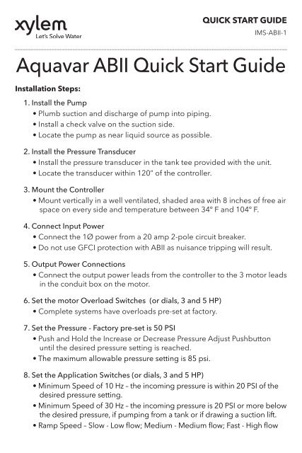
Installation Steps:<br />
1. Install the Pump<br />
• Plumb suction and discharge of pump into piping.<br />
• Install a check valve on the suction side.<br />
• Locate the pump as near liquid source as possible.<br />
2. Install the Pressure Transducer<br />
• Install the pressure transducer in the tank tee provided with the unit.<br />
• Locate the transducer within 120” of the controller.<br />
3. Mount the Controller<br />
• Mount vertically in a well ventilated, shaded area with 8 inches of free air<br />
space on every side and temperature between 34º F and 104º F.<br />
4. Connect Input Power<br />
• Connect the 1Ø power from a 20 amp 2-pole circuit breaker.<br />
• Do not use GFCI protection with <strong>ABII</strong> as nuisance tripping will result.<br />
5. Output Power Connections<br />
• Connect the output power leads from the controller to the 3 motor leads<br />
in the conduit box on the motor.<br />
6. Set the motor Overload Switches (or dials, 3 and 5 HP)<br />
• Complete systems have overloads pre-set at factory.<br />
QUICK START GUIDE<br />
IMS-<strong>ABII</strong>-1<br />
7. Set the Pressure - Factory pre-set is 50 PSI<br />
• Push and Hold the Increase or Decrease Pressure Adjust Pushbutton<br />
until the desired pressure setting is reached.<br />
• The maximum allowable pressure setting is 85 psi.<br />
8. Set the Application Switches (or dials, 3 and 5 HP)<br />
• Minimum Speed of 10 Hz – the incoming pressure is within 20 PSI of the<br />
desired pressure setting.<br />
• Minimum Speed of 30 Hz – the incoming pressure is 20 PSI or more below<br />
the desired pressure, if pumping from a tank or if drawing a suction lift.<br />
• Ramp Speed – Slow - Low flow; Medium - Medium flow; Fast - High flow
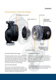
<strong>Aquavar</strong> <strong>ABII</strong> Controller<br />
Typical Installation<br />
This diagram shows a set-up for municipal water connection. This allows pump<br />
maintenance without main line shut-off.<br />
Home Supply <strong>Water</strong> Main<br />
Disconnect<br />
AquaBoost<br />
Controller<br />
Circuit<br />
Breaker<br />
Gauge<br />
Tank<br />
Motor/Pump<br />
Transducer<br />
AquaBoost II Required Components:<br />
1. Pump with Motor<br />
Relief<br />
Valve<br />
Check Valve<br />
To Drain<br />
Check Valve<br />
Isolation Valves<br />
Unions<br />
2. AquaBoost II Controller with Integral Pressure Sensor Cable<br />
3. Pressure Tank<br />
4. Pressure Sensor<br />
5. Mounting Kit<br />
6. Tank Tee with Pipe Plug<br />
7. Pressure Gauge<br />
<strong>Xylem</strong> Inc.<br />
www.xyleminc.com<br />
© 2011 <strong>Xylem</strong> Inc. IMS-<strong>ABII</strong>-1 December 2011
<strong>Aquavar</strong> <strong>ABII</strong><br />
<strong>Quick</strong> <strong>Start</strong> Up <strong>Guide</strong><br />
LABELS FOUND ON THE CONTROLLER ACCESS COVER:<br />
Motor Overload Setting<br />
WARNING: Disconnect Power And Wait For LED Indicator To<br />
Turn Off Before Touching Motor Overload Setting Switches.<br />
1 = UP 0 = DOWN<br />
DIP Switch Setting Motor Overload Setting (Amps)<br />
1 2 3 4 1AB2 2AB2<br />
1 1 1 1 2.5 4.6<br />
1 1 1 0 2.8 5.2<br />
1 1 0 1 3.3 5.3<br />
1 0 1 1 3.5 5.8<br />
0 1 1 1 3.8 6.5<br />
0 0 0 0 4.2 6.9<br />
Motor Overload Setting Label<br />
Use this label to choose the correct Motor Overload Switch<br />
Setting. This label is found under the controller access cover.<br />
Status Code Label<br />
Use this label to diagnose any system errors. This label is<br />
found on the side of the controller access cover.<br />
Application Switch Setting<br />
Fault Codes<br />
Status Codes*<br />
Green Light Codes<br />
Constant Standby/Low Voltage<br />
Blinking Pump Running<br />
Red Light Codes<br />
Constant Replace Controller<br />
1 Blink No <strong>Water</strong>/Loss Of Prime<br />
2 Blinks Tank <strong>Water</strong>-Logged<br />
3 Blinks Pressure Sensor Fault<br />
4 Blinks Pump or Motor Bound<br />
5 Blinks Short Circuit<br />
6 Blinks Ground Fault<br />
7 Blinks High Temperature<br />
8 Blinks Over Voltage (>264V)<br />
9 Blinks Motor Overload<br />
*No Light - No/Very Low Voltage<br />
WARNING: Disconnect Power And Wait For LED Indicator To Turn<br />
Off Before Touching Application Setting Switches.<br />
DIP Switch Setting 1 = UP 0 = DOWN<br />
1 2 3 4 Minimum Speed (Hz) Ramp Setting<br />
1 1 1 1 * 10 Slow<br />
1 1 1 0 * 10 Medium<br />
1 1 0 1 * 10 Fast<br />
1 0 1 1 30 Slow<br />
0 1 1 1 30 Medium<br />
0 0 0 0 30 Fast<br />
*THESE SETTINGS ARE NOT TO BE USED WITH SUBMERSIBLE PUMPS.<br />
QUICK START GUIDE<br />
IMS-<strong>ABII</strong>-2<br />
Application<br />
Switch<br />
Setting<br />
Label<br />
Use this label<br />
to choose<br />
the correct<br />
Application<br />
Switch Setting.<br />
This label is<br />
found under<br />
the controller<br />
access cover.
<strong>Aquavar</strong> <strong>ABII</strong> Wiring Diagram<br />
1 AND 2 HP<br />
GND<br />
GREEN<br />
Input<br />
230V<br />
1 Phase<br />
L1<br />
BLACK<br />
Line input power from<br />
2-pole disconnect or<br />
circuit breaker.<br />
L2 (N)<br />
BLACK<br />
See Manual For<br />
Switch Settings<br />
Applic.<br />
Type<br />
Motor<br />
Overload<br />
Setting<br />
1 2 3 4 1 2 3 4<br />
Output<br />
To Motor<br />
T1<br />
T2<br />
T3<br />
GND<br />
BLUE<br />
RED<br />
BLACK<br />
GREEN<br />
Pressure<br />
Transducer<br />
Line output to motor.<br />
Correct motor rotation<br />
determines order of colors.<br />
Note: Verify controller voltage input on label. 115 volt or 230 volt.<br />
3 AND 5 HP<br />
* Input Power Supply<br />
Single Phase<br />
208-240 VAC<br />
Note: Use 2 pole disconnect<br />
or circuit breaker.<br />
<strong>Xylem</strong> Inc.<br />
www.xyleminc.com<br />
GROUND<br />
© 2011 <strong>Xylem</strong> Inc. IMS-<strong>ABII</strong>-2 December 2011<br />
INPUT BLOCK<br />
Com. (Blk)<br />
OUTPUT BLOCK<br />
Input (Wht)<br />
+5V (Red)<br />
WHITE<br />
RED<br />
BLACK<br />
L1 L2 GND GND RED BLK YEL<br />
GROUND<br />
230 VOLT<br />
THREE PHASE<br />
MOTOR<br />
THREE PHASE<br />
MOTOR<br />
OUTPUT<br />
Pressure<br />
Transducer