Overhead SF6 Insulated Switching Catalog - G&W Electric
Overhead SF6 Insulated Switching Catalog - G&W Electric
Overhead SF6 Insulated Switching Catalog - G&W Electric

You also want an ePaper? Increase the reach of your titles
YUMPU automatically turns print PDFs into web optimized ePapers that Google loves.
LINEAR PUFFER SWITCHES<br />
G&W’s overhead Linear Puffer (LP)<br />
load break switches are designed<br />
for operation on distribution systems<br />
rated through 38kV, 630A continuous<br />
and 40kA asymmetrical short circuit.<br />
LP switches can accommodate<br />
almost every user switching requirement.<br />
The switches are designed<br />
and tested to applicable ANSI and<br />
IEC standards.<br />
FEATURES<br />
Refer to G&W’s Solution Advantage<br />
section, page 3 for general features.<br />
Heavy Duty Ratings — LP switches<br />
are designed for rugged duty<br />
applications. Switches are tested<br />
and rated to 40kA rms asymmetrical<br />
momentary and fault close, 1200<br />
loadbreak operations at full rated<br />
current and 2000 mechanical operations.<br />
Visible Open/Close — A color<br />
coded contact indicator (greenopen,<br />
red- closed) is standard and<br />
easily visible from ground level. An<br />
optional viewing window is available<br />
permitting visible verifi cation of contact<br />
position for all 3 phases.<br />
Page 8<br />
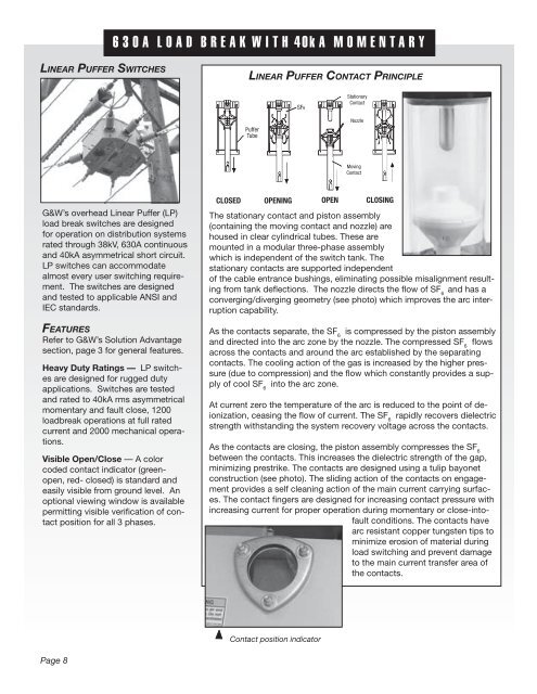
630A LOAD BREAK WITH 40kA MOMENTARY<br />
LINEAR PUFFER CONTACT PRINCIPLE<br />
Puffer<br />
Tube<br />
<strong>SF6</strong><br />
Stationary<br />
Contact<br />
Nozzle<br />
Moving<br />
Contact<br />
CLOSED OPENING OPEN CLOSING<br />
The stationary contact and piston assembly<br />
(containing the moving contact and nozzle) are<br />
housed in clear cylindrical tubes. These are<br />
mounted in a modular three-phase assembly<br />
which is independent of the switch tank. The<br />
stationary contacts are supported independent<br />
of the cable entrance bushings, eliminating possible misalignment resulting<br />
from tank defl ections. The nozzle directs the fl ow of SF 6 and has a<br />
converging/diverging geometry (see photo) which improves the arc interruption<br />
capability.<br />
As the contacts separate, the SF 6 is compressed by the piston assembly<br />
and directed into the arc zone by the nozzle. The compressed SF 6 fl ows<br />
across the contacts and around the arc established by the separating<br />
contacts. The cooling action of the gas is increased by the higher pressure<br />
(due to compression) and the fl ow which constantly provides a supply<br />
of cool SF 6 into the arc zone.<br />
At current zero the temperature of the arc is reduced to the point of deionization,<br />
ceasing the fl ow of current. The SF 6 rapidly recovers dielectric<br />
strength withstanding the system recovery voltage across the contacts.<br />
As the contacts are closing, the piston assembly compresses the SF 6<br />
between the contacts. This increases the dielectric strength of the gap,<br />
minimizing prestrike. The contacts are designed using a tulip bayonet<br />
construction (see photo). The sliding action of the contacts on engagement<br />
provides a self cleaning action of the main current carrying surfaces.<br />
The contact fi ngers are designed for increasing contact pressure with<br />
increasing current for proper operation during momentary or close-intofault<br />
conditions. The contacts have<br />
arc resistant copper tungsten tips to<br />
minimize erosion of material during<br />
load switching and prevent damage<br />
to the main current transfer area of<br />
the contacts.<br />
Contact position indicator