Overhead SF6 Insulated Switching Catalog - G&W Electric
Overhead SF6 Insulated Switching Catalog - G&W Electric
Overhead SF6 Insulated Switching Catalog - G&W Electric

You also want an ePaper? Increase the reach of your titles
YUMPU automatically turns print PDFs into web optimized ePapers that Google loves.
GW20-SG5-OS07<br />
May, 2007<br />
Supersedes SG5-OS3<br />
OVERHEAD<br />
SF 6 INSULATED<br />
SWITCHING SOLUTIONS<br />
For applications through 38kV<br />
• Load break switching to 630A<br />
• Manual or automated solutions<br />
• Automatic sectionalizing<br />
• Mounting flexibility<br />
• Custom solutions since 1905<br />
<strong>Catalog</strong> SG5-OS07
WORLDWIDE EXPERIENCE AND WORLDCLASS PERFORMANCE<br />
G&W <strong>Electric</strong> headquarters located in Blue Island, Illinois USA.
Since 1905, G&W has been providing<br />
high quality electrical products<br />
and innovative system solutions to<br />
utilities and electrical power users<br />
around the world. Considered a<br />
pioneer in the evolution of today’s<br />
switchgear, cable splicing and<br />
termination technology, G&W has<br />
become the fi rst in our industry to<br />
achieve both the prestigious ISO<br />
9001:2000 and ISO 14001 certifi -<br />
cations. By combining extensive<br />
product development with state-ofthe-art<br />
manufacturing, G&W continues<br />
to set the standard for quality<br />
switching and fault interrupting<br />
products. Whether the application<br />
involves load switching, line<br />
sectionalizing, fault interruption or<br />
distribution automation, G&W offers<br />
a solution for overhead distribution<br />
system switching and protection.<br />
LOAD BREAK SOLUTIONS<br />
G&W overhead load break switches<br />
are designed with all critical contact<br />
components totally protected from<br />
the environment within a sealedfor-life<br />
(per IEC standards), welded<br />
steel enclosure. Because contacts<br />
are totally sealed, they are not<br />
subject to corrosion caused by salt<br />
G&W’s SOLUTION ADVANTAGE<br />
or other airborne contaminants. Icing,<br />
which can hamper proper operation of<br />
exposed switching mechanisms, is also<br />
not a concern. SF 6 is used because<br />
it is a safe, nontoxic, nonfl ammable,<br />
stable dielectric with excellent arc<br />
quenching properties. G&W overhead<br />
load break switches are durable and<br />
maintenance-free assuring a long service<br />
life without recurring maintenance<br />
costs.<br />
A variety of load break switch designs<br />
are available for manual or electrically<br />
operated load switching for systems<br />
through 38kV.<br />
Other features include:<br />
Testing to ANSI and IEC standards.<br />
Bushing fl exibility<br />
Ease of automation<br />
Compared To Air Break Switches<br />
G&W overhead load break switches<br />
can provide:<br />
An economical alternative with<br />
superior, mechanical and electrical<br />
performance.<br />
Totally sealed contact systems<br />
eliminating environmental corrosion<br />
and icing concerns.<br />
TABLE OF CONTENTS<br />
Signifi cant increase in the<br />
number of load break operations<br />
which is especially important in<br />
automation schemes where the<br />
number of switching operations<br />
typically increases.<br />
Minimal maintenance.<br />
Ease of automation.<br />
FAULT INTERRUPTING<br />
G&W’s Solution Advantage/ General Features .................... page 3<br />
<strong>Overhead</strong> <strong>Switching</strong> Applications ....................................... page 4<br />
Load Break Switches with 20kA Momentary ................. pages 5-7<br />
Load Break Switches with 40kA Momentary ............... pages 8-10<br />
Automation Solutions ................................................... page 11-12<br />
Switch Accessories / Options .................................... pages 13-14<br />
Ratings and Standards ...................................................... page 15<br />
SOLUTIONS<br />
For applications requiring overcurrent<br />
protection, G&W offers a<br />
variety of automatic reclosers and<br />
sectionalizers. Solid dielectric,<br />
three phase vacuum reclosers are<br />
available through 38kV, 800A continuous,<br />
12.5kA symmetrical interrupting.<br />
Various bushing confi gurations<br />
permit application versatility.<br />
Reclosers work directly with the<br />
popular Schweitzer SEL 351R<br />
control and others. See separate<br />
catalog for detailed information.<br />
Page 3
SWITCH APPLICATIONS<br />
Switches play a fundamental role in<br />
improving distribution reliability. By<br />
applying switches in strategic locations<br />
on the distribution system,<br />
faults can be isolated while minimizing<br />
the outage area, loads can<br />
be distributed according to system<br />
conditions, critical loads can be<br />
kept on line, individual protective<br />
devices or sections of line can be<br />
bypassed during routine maintenance,<br />
and loads can be dropped to<br />
prevent overloading the source. In<br />
short, switches are typically used to<br />
recon-fi gure a distribution system<br />
to minimize outages and increase<br />
system reliability.<br />
MANUAL SWITCHING<br />
By installing manually operated<br />
switches, a user can economically<br />
redistribute power during times of<br />
planned outages for routine line<br />
maintenance, equipment replacement,<br />
or even seasonal load adjustments.<br />
Manual switches can also<br />
be used to isolate faults in areas<br />
where immediate power restoration<br />
is not necessary, or to perform an<br />
emergency sectionalizing function<br />
to quickly restore power to the customers<br />
affected by a power outage.<br />
G&W offers a variety of switch styles<br />
depending on system ratings and<br />
automation requirements, if applicable.<br />
G&W switches do not require<br />
de-energizing the system prior to<br />
switching so customer service is not<br />
disrupted.<br />
AUTOMATED SWITCHING<br />
By adding a motor actuator and<br />
controller to the switch operating<br />
mechanism, the user can perform<br />
all of the functions of a manually<br />
operated switch without having to<br />
dispatch a crew to the switch site.<br />
Various automation control packages<br />
are available to suit many application<br />
requirements.<br />
Page 4<br />
OVERHEAD SWITCHING APPLICATIONS<br />
Local Control<br />
Adding a motor actuator and a<br />
stand-alone electronic motor<br />
controller can provide simple push-<br />
button operation from ground level.<br />
Fault Isolation<br />
When combined with a stand-alone<br />
control and sensors, a switch can be<br />
used as a self-contained automatic<br />
sectionalizing device for automatic<br />
fault isolation. Different sectionalizing<br />
controls with voltage and/or current<br />
sensors are available. Typically<br />
automatic sectionalizers utilize either<br />
time-current sensing or time-voltage<br />
sensing controls which can be used<br />
for opening line sectionalizers, or<br />
controls which require a combination<br />
of voltage with current sensing.<br />
All of these logic schemes require a<br />
fault interrupting device to be upline<br />
from the sectionalizing switches.<br />
The protective device must be either<br />
locked out or programmed for a<br />
specifi c reclose interval plus a time<br />
safety factor to allow the switch to<br />
operate.<br />
Tie Switches<br />
For tie applications, the switch<br />
control senses a voltage loss on<br />
either the source or the load side to<br />
determine whether or not to close in<br />
from a normally open condition between<br />
two different sources. A time<br />
component is generally required in<br />
the control logic to insure the loss<br />
of voltage on either of the sources<br />
is permanent. Once the voltage on<br />
one source has been lost for a preprogrammed<br />
period of time, the tie<br />
switch will close in restoring power<br />
to the de-energized line.<br />
Current sensors can be added to the<br />
tie switch to tell a controller that a<br />
fault exists when the main contacts<br />
are closed. For a normally open tie,<br />
the tie may close into a fault upon<br />
loss of voltage on one feeder. The<br />
control “knows” of the faulted condition<br />
and would not open unless<br />
it detects a loss of voltage on the<br />
faulted feeder side signifying the upline<br />
protective device has operated.<br />
On a normally closed tie, the switch<br />
control would use similar logic, but<br />
no fault closing would be necessary<br />
prior to isolating the fault.<br />
Tie switches can also be applied<br />
to automatically bypass a feeder<br />
which has locked out due to a<br />
failure, planned outage or a faulted<br />
line. If the switch closes into a fault,<br />
the tie switch would open once<br />
the upline protective device has<br />
opened, de-energizing the line.<br />
Loop Schemes<br />
Loop schemes generally consist of<br />
two or more sources tied into a distribution<br />
system to assure backup<br />
power is available if the primary<br />
feeder is lost. The scheme utilizes<br />
sectionalizing and tie switches to<br />
automatically isolate the fault and<br />
restore power to all areas unaffected<br />
by the fault quickly and reliably<br />
using the same principles and<br />
methods described previously.<br />
Automatic Transfer<br />
For critical load applications such<br />
as hospitals, processing plants,<br />
military bases, etc., automatic<br />
transfer schemes are common. For<br />
overhead systems, this scheme<br />
requires two switches, voltage and<br />
current sensors and a voltage-time<br />
controller. Basically, a loss of voltage<br />
on the primary source is sensed<br />
and initiates the controller to open<br />
the primary and close the alternate<br />
source switch to automatically<br />
restore power. Current sensing is<br />
used to prevent closing into a load<br />
side fault. G&W offers a variety of<br />
automatic transfer packages.<br />
SCADA / Distribution Automation<br />
Switches can perform the above<br />
functions either autonomously or<br />
through a SCADA system where the<br />
switch controls incorporate RTUs<br />
for interfacing with a master station.<br />
A variety of SCADA applications<br />
are available which employ either a<br />
master-slave or peer-to-peer communications<br />
architecture.
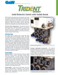
ROTARY PUFFER SWITCHES<br />
G&W’s overhead Rotary Puffer (RP)<br />
switches are ideal for manual load<br />
break switching, standard speed (5<br />
seconds per operation) automatic<br />
transfer or automated sectionalizing<br />
on systems rated through 27kV,<br />
630A continuous, 32kA peak and<br />
20kA asymmetrical short circuit.<br />
The switches are tested to applicable<br />
sections of ANSI and IEC<br />
standards.<br />
FEATURES<br />
Refer to G&W’s Solution Advantage<br />
section, page 3 for general features.<br />
Economical Package — The manual<br />
overhead RP switch is G&W’s<br />
most cost effective alternative to<br />
traditional gang operated air break<br />
switches.<br />
Ease of Operation — The rotary<br />
puffer mechanism is extremely easy<br />
to operate whether from a bucket<br />
truck or ground level operator. The<br />
handle can be padlocked in the open<br />
or closed position. Downrod assemblies<br />
are available.<br />
Self-disengaging Motor<br />
Actuator — For applications requiring<br />
motor control, an exclusive motor<br />
actuator assembly permits easy<br />
manual operation if control power is<br />
lost. The main shaft automatically<br />
disengages from the motor gear assembly<br />
after each electrical operation<br />
permitting virtually effortless<br />
manual operation.<br />
630A LOAD BREAK WITH 20kA MOMENTARY<br />
Rotor<br />
Moving<br />
Contact<br />
Stator<br />
ROTARY PUFFER CONTACT PRINCIPLE<br />
Stationary<br />
Contact<br />
Nozzle<br />
Impeller<br />
The stationary contacts and the multi-chamber rotor (an assembly of<br />
interlocking parts which form a rotational framework including moving<br />
contacts) are housed in a clear cylindrical shell. The stationary<br />
contacts are supported independent of the cable entrance bushings,<br />
eliminating possible misalignment resulting from tank defl ections.<br />
Each rotating contact simultaneously disengages from two stationary<br />
contacts per phase, providing improved interrupting capability as<br />
compared to single break contact systems.<br />
As the rotor tube assembly turns to disengage the moving contacts,<br />
SF 6 gas is compressed between the impeller and stator. The shell,<br />
phase barrier and rotor tube also act to confi ne the gas for proper<br />
compression and fl ow. The compressed SF 6 gas is directed through<br />
the nozzle into the arc zone. The SF 6 fl ows across the contacts cooling<br />
the arc over the length of the nozzle. The cooling action is increased<br />
by the higher pressure (due to compression) and the fl ow of<br />
gas which constantly provides a supply of cool SF 6 into the arc zone.<br />
At current zero, the temperature of the arc is reduced to the point of<br />
deionization. The SF 6 gas rapidly recovers dielectric strength withstanding<br />
the system recovery voltage across the contacts. As the<br />
rotor tube assembly turns to engage the moving contacts with the<br />
stationary contacts, the impeller induces a fl ow of SF 6 gas between<br />
the contacts to minimize prestrike.<br />
Visible Open/Close — The color<br />
coded main contact position indicator<br />
(green-open, red-closed) is<br />
easily visible from the ground. The<br />
indicator is connected directly to the<br />
main contact drive shaft assembly<br />
assuring accurate contact status.<br />
Refer to Automation, Typical<br />
Specifi cations and Accessories<br />
sections for more details.<br />
RP Contact Module<br />
Contact postion indicator<br />
Page 5
Approximate Dimensions 15.5kV with Pole Mounting Bracket<br />
Feedthru Connectors for Cable<br />
(supplied on motor<br />
operated unit only)<br />
9.00"<br />
(229mm)<br />
19.00"<br />
(483mm)<br />
Page 6<br />
FRONT VIEW<br />
13.00"<br />
(330mm)<br />
630A LOAD BREAK WITH 20kA MOMENTARY<br />
ROTARY PUFFER SWITCHES (CONT.)<br />
Voltage Approximate<br />
One-line Max <strong>Catalog</strong> Weight w/SF 6<br />
Diagram kV Number lbs. (kgs)<br />
15.5<br />
27<br />
Ground Boss with<br />
1/2" - 13 Thread<br />
ORA21-376-20RP<br />
ORA21-386-20RP<br />
52.00"<br />
(1321mm)<br />
BOTTOM VIEW<br />
20.00"<br />
(508mm)<br />
235<br />
(107)<br />
Viewing Window for<br />
Pressure Gauge & Contact<br />
Position Indicator<br />
Crossarm<br />
Mounting Bracket<br />
Optional<br />
Aerial Lugs<br />
Operator Handle with<br />
Provisions for Padlocking<br />
in all Positions<br />
Crossarm Mounting<br />
Kit includes two galvanized, predrilled angle<br />
channels, four stainless steel J bolts and hardware.<br />
Lifting Provisions<br />
With (4) 1.25"<br />
Diameter Holes<br />
Vent<br />
Typical Vertical Mounting<br />
6.00"<br />
(153mm)<br />
32.00"<br />
(813mm)<br />
8.00"<br />
(203mm)<br />
SIDE VIEW<br />
Optional 4/0<br />
Ground Lug<br />
7.00"<br />
(178mm)<br />
25.00"<br />
635mm
TYPICAL SPECIFICATIONS<br />
ROTARY PUFFER SWITCHES<br />
GENERAL<br />
This specifi cation covers the requirements<br />
for manual load interrupting<br />
SF 6 rotary puffer (RP style)<br />
switches for overhead applications.<br />
Design Ratings and Standards<br />
Switches shall be designed, tested,<br />
and built per applicable sections<br />
of ANSI and IEC standards. Certifi<br />
ed test reports shall be provided.<br />
The manufacturer shall be ISO<br />
9001:2000 and 14001 certifi ed. The<br />
switch assembly shall be rated:<br />
Maximum design voltage,<br />
kV .......................15.5 ........... 27<br />
Impulse level (BIL),<br />
kV ......................110 .......... 125<br />
One minute withstand (dry),<br />
AC kV ..................50 ............ 60<br />
10 second withstand (wet),<br />
AC kV ..................45 .............. 50<br />
15 minute withstand,<br />
DC kV ..................53 .............. 78<br />
Continuous and load break current,<br />
Amps .................................... 630<br />
Momentary current,<br />
kA asym.................................. 20<br />
Fault-close current,<br />
kA asym (3 times) ................... 20<br />
One second current,<br />
kA sym ................................... 12<br />
Operations load interrupting<br />
endurance at 600A ............... 500<br />
Mechanical endurance,<br />
operations .......................... 2000<br />
Maximum gas leakage test,<br />
cc/second ............................ 10 -7<br />
The above ratings apply to the switch<br />
assembly and may be reduced depending<br />
upon the entrances chosen. Also<br />
see Rating and Standards, page 15.<br />
Switch Construction<br />
Switch contacts and cable entrance<br />
terminations shall be contained in<br />
a single welded, mild steel tank<br />
with entrances internally connected<br />
by tin plated copper. The protection<br />
degree of the switch tank shall<br />
be IPX7 rated. Switches shall be<br />
shipped fi lled with SF 6 gas at approx.<br />
9 psig (60kPa).<br />
630A LOAD BREAK WITH 20kA MOMENTARY<br />
Switch Contacts<br />
Switch contacts shall be of a rotary<br />
puffer design made with copper<br />
alloy contacts with silver plating<br />
to assure permanent, low contact<br />
resistance. Each rotating contact<br />
simultaneously disengages from<br />
two fi xed contacts, thus providing<br />
two break points per phase which<br />
gives improved interrupting capability<br />
as compared to switches with<br />
only a single set of break contacts.<br />
Contact travel shall be 90º to assure<br />
effi cient arc extinction and a wide<br />
open contact gap. Arcing is confi<br />
ned away from the main contact<br />
surfaces. The stationary contacts<br />
shall be supported independent<br />
of the cable entrance bushings,<br />
eliminating possible misalignment.<br />
Temperature rise shall not exceed<br />
ANSI C37.71 and IEC 265-1 standards<br />
for this type of device.<br />
Switch Operation<br />
Each switch shall be equipped with<br />
spring assisted operating mechanism<br />
capable of providing quick -<br />
make, quick-break operation. The<br />
mechanism shall be capable of<br />
delivering suffi cient torque and shall<br />
be provided with latches for each<br />
position to achieve the published<br />
load interrupting, fault closing, and<br />
momentary ratings. All switch positions<br />
shall be clearly identifi ed and<br />
padlockable.<br />
The operating mechanism shall be<br />
actuated from outside the switch<br />
tank by a permanently attached<br />
operating handle or motor actuator.<br />
The operating shaft shall be made<br />
of brass for maximum corrosion<br />
resistance. A double “O” ring type<br />
operating shaft seal shall be used<br />
for a leak resistant, long life seal.<br />
Ambient temperature range shall be<br />
-30ºC to +40ºC (-22ºF to +104ºF).<br />
Standard Components<br />
For a manual switch the following<br />
shall be included:<br />
1) Eleven gauge mild steel tank<br />
painted light gray with stainless<br />
steel and brass fasteners.<br />
2) Two lifting eyes.<br />
3) Crossarm or pole mounting<br />
bracket and hardware.<br />
4) Grounding provisions.<br />
5) Gas pressure gauge and fi ll valve.<br />
6) Three line diagram and corrosion<br />
resistant nameplate.<br />
7) Spring operator.<br />
8) Manual operating handle.<br />
9) Colored contact position indica-<br />
tor (open/green, closed/red).<br />
10) Padlock provisions for open and<br />
close positions.<br />
11) Porcelain bushings with copper<br />
conducter and hoodnut.<br />
12) Lightning arrester provisions.<br />
13) Operations counter.<br />
Mounting<br />
Switches shall be equipped with<br />
(check one):<br />
❏ Crossarm mounting kit<br />
❏ Polemount bracket (horizontal)<br />
❏ Polemount bracket (vertical)<br />
Options<br />
The following options shall be supplied:<br />
❏ Stainless steel tank.<br />
❏ Low pressure warning device.<br />
❏ Temperature compensated gas<br />
density gauge<br />
❏ 4/0 brass ground lug.<br />
❏ NEMA 2-hole aerial lugs.<br />
❏ NEMA 4-hole aerial lugs.<br />
❏ Clamp style aerial lugs.<br />
❏ Overpressure relief device.<br />
❏ Wildlife protectors.<br />
❏ Lightning arresters.<br />
❏ Potential transformers.<br />
❏ Current transformers<br />
(600:5) (500:1) (1000:1)<br />
❏ Down rod operator kit.<br />
Does not include rods.<br />
❏ Motor actuator<br />
❏ Analog voltage sensors.<br />
❏ 600A porcelain bushings with<br />
copper rod.<br />
❏ 600A apparatus bushing with<br />
elastomeric insulator and (AL)<br />
(CU) rod.<br />
❏ 600A apparatus bushing with<br />
(AL) (CU) rod.<br />
❏ Automation accessories.<br />
Page 7
LINEAR PUFFER SWITCHES<br />
G&W’s overhead Linear Puffer (LP)<br />
load break switches are designed<br />
for operation on distribution systems<br />
rated through 38kV, 630A continuous<br />
and 40kA asymmetrical short circuit.<br />
LP switches can accommodate<br />
almost every user switching requirement.<br />
The switches are designed<br />
and tested to applicable ANSI and<br />
IEC standards.<br />
FEATURES<br />
Refer to G&W’s Solution Advantage<br />
section, page 3 for general features.<br />
Heavy Duty Ratings — LP switches<br />
are designed for rugged duty<br />
applications. Switches are tested<br />
and rated to 40kA rms asymmetrical<br />
momentary and fault close, 1200<br />
loadbreak operations at full rated<br />
current and 2000 mechanical operations.<br />
Visible Open/Close — A color<br />
coded contact indicator (greenopen,<br />
red- closed) is standard and<br />
easily visible from ground level. An<br />
optional viewing window is available<br />
permitting visible verifi cation of contact<br />
position for all 3 phases.<br />
Page 8<br />
630A LOAD BREAK WITH 40kA MOMENTARY<br />
LINEAR PUFFER CONTACT PRINCIPLE<br />
Puffer<br />
Tube<br />
<strong>SF6</strong><br />
Stationary<br />
Contact<br />
Nozzle<br />
Moving<br />
Contact<br />
CLOSED OPENING OPEN CLOSING<br />
The stationary contact and piston assembly<br />
(containing the moving contact and nozzle) are<br />
housed in clear cylindrical tubes. These are<br />
mounted in a modular three-phase assembly<br />
which is independent of the switch tank. The<br />
stationary contacts are supported independent<br />
of the cable entrance bushings, eliminating possible misalignment resulting<br />
from tank defl ections. The nozzle directs the fl ow of SF 6 and has a<br />
converging/diverging geometry (see photo) which improves the arc interruption<br />
capability.<br />
As the contacts separate, the SF 6 is compressed by the piston assembly<br />
and directed into the arc zone by the nozzle. The compressed SF 6 fl ows<br />
across the contacts and around the arc established by the separating<br />
contacts. The cooling action of the gas is increased by the higher pressure<br />
(due to compression) and the fl ow which constantly provides a supply<br />
of cool SF 6 into the arc zone.<br />
At current zero the temperature of the arc is reduced to the point of deionization,<br />
ceasing the fl ow of current. The SF 6 rapidly recovers dielectric<br />
strength withstanding the system recovery voltage across the contacts.<br />
As the contacts are closing, the piston assembly compresses the SF 6<br />
between the contacts. This increases the dielectric strength of the gap,<br />
minimizing prestrike. The contacts are designed using a tulip bayonet<br />
construction (see photo). The sliding action of the contacts on engagement<br />
provides a self cleaning action of the main current carrying surfaces.<br />
The contact fi ngers are designed for increasing contact pressure with<br />
increasing current for proper operation during momentary or close-intofault<br />
conditions. The contacts have<br />
arc resistant copper tungsten tips to<br />
minimize erosion of material during<br />
load switching and prevent damage<br />
to the main current transfer area of<br />
the contacts.<br />
Contact position indicator
A B<br />
27.00"<br />
(686mm)<br />
630A LOAD BREAK WITH 40kA MOMENTARY<br />
Voltage Approximate<br />
One-line Max <strong>Catalog</strong> Weight w/SF 6<br />
Diagram kV Number lbs. (kgs)<br />
15.5 ORA21-376-40PI<br />
27 ORA21-386-40PI<br />
38 ORA21-396-40PI<br />
Approximate Dimensions (15.5 kV)<br />
Typical Horizontal Mounting<br />
65.00"<br />
(1651mm)<br />
31.00"<br />
(787mm)<br />
Pressure Gauge, Fill<br />
Valve & Low Pressure<br />
Warning Device<br />
(optional) Ground Boss With<br />
1/2"—13 Internal Thread<br />
Operating Shaft and Locking<br />
Assembly With Fixed<br />
Handle<br />
Contact<br />
Position<br />
Indicator<br />
Optional<br />
Motor<br />
Operator<br />
Direct Pole<br />
Mount Bracket<br />
285<br />
(130)<br />
Optional<br />
Viewing Window<br />
10"<br />
(254mm)<br />
Optional<br />
Aerial<br />
Lugs<br />
Typical Vertical Mounting<br />
Crossarm Mounting<br />
Kit includes two galvanized, predrilled angle<br />
channels, four stainless steel J bolts and hardware.<br />
7.00"<br />
(178mm)<br />
6.00"<br />
(153mm)<br />
8.00"<br />
(203mm)<br />
Page 9
TYPICAL SPECIFICATIONS<br />
LINEAR PUFFER SWITCHES<br />
GENERAL<br />
This specifi cation covers the requirements<br />
for manual load interrupting<br />
SF 6 linear puffer (LP style)<br />
switches for overhead applications.<br />
Design Ratings and Standards<br />
Switches are to be designed, tested,<br />
and built per applicable sections<br />
of ANSI and IEC standards. Certifi<br />
ed test reports shall be provided.<br />
The manufacturer shall be ISO<br />
9001:2000 and 14001 certifi ed. The<br />
switch assembly shall be rated:<br />
Maximum design voltage,<br />
kV ................15.5 ......27 ........ 38<br />
Impulse level (BIL),<br />
kV .................110 ......125 ...... 150<br />
One minute withstand (dry),<br />
AC kV ...........50 .........60 ........ 70<br />
10 second withstand (wet)<br />
AC kV .............. 45 ....50 ......... 60<br />
15 minute withstand<br />
DC kV ..........53 ........78 ....... 103<br />
Continuous and load break current,<br />
Amps ...................................... 630<br />
Momentary current,<br />
kA asym ................................... 40<br />
Fault-close current,<br />
kA asym (3 times) ..................... 40<br />
One second current,<br />
kA sym .................................... 25<br />
Open gap withstand,<br />
kV .......................................... 200<br />
10 operating overload interrupting .<br />
capability, Amps ................... 3000<br />
Operations load interrupting<br />
endurance at 600A ............... 1200<br />
Mechanical endurance,<br />
operations ............................ 2000<br />
Maximum gas leakage test,<br />
cc/second .............................. 10 -7<br />
The above ratings apply to the switch<br />
assembly and may be reduced depending<br />
upon the entrances chosen. Also<br />
see Rating and Standards, page 15.<br />
Switch Construction<br />
All switch components and entrances<br />
shall be assembled in a single<br />
welded, mild steel tank. Entrances<br />
Page 10<br />
630A LOAD BREAK WITH 40kA MOMENTARY<br />
shall be internally connected by<br />
copper wire ropes and copper bus<br />
capable of handling momentary<br />
and continuous current duty. The<br />
protection degree of the switch tank<br />
shall be IPX7 rated. Switches shall<br />
be shipped fi lled with SF 6 gas at<br />
approx. 9 psig (60kPa).<br />
Switch Operation<br />
Each switch shall be equipped with<br />
an internally mounted rotary type<br />
operating mechanism capable of<br />
providing quick -make, quick-break<br />
operation. The mechanism must<br />
be capable of delivering suffi cient<br />
torque and shall be provided with<br />
latches for each position. The<br />
mechanism shall use compression<br />
type springs to assure long life and<br />
reliability. All switch positions are to<br />
be clearly identifi ed and padlockable.<br />
The operating mechanism<br />
shall be actuated from outside the<br />
switch tank by an external operating<br />
handle. The operating shaft shall be<br />
made of stainless steel for maximum<br />
corrosion resistance. A double<br />
“O” ring type operating shaft seal<br />
shall be used for a leak resistant,<br />
long life seal. Ambient temperature<br />
range shall be -30ºC to +40ºC<br />
(-22ºF to +104ºF).<br />
Switch Contacts<br />
Switch contacts shall be linear puffer<br />
style tulip-bayonet design and made<br />
of plated, high-conductivity copper<br />
alloy with arcing tips of copper/tungsten<br />
alloy. The contacts shall be<br />
designed such that arcing does not<br />
occur in the area of main current<br />
interchange and contact pressure<br />
will increase with increasing current<br />
fl ow. The contact nozzle shall have a<br />
converging/diverging geometry which<br />
improves the fl ow of SF 6 into the arc<br />
zone. Contact travel shall be three<br />
inches and have suffi cient open contact<br />
separation to assure effi cient arc<br />
extinction and to withstand fi eld DC<br />
testing levels and maintain BIL levels.<br />
The stationary contacts shall be<br />
supported independent of the cable<br />
entrance bushings. Temperature rise<br />
shall not exceed ANSI C37.71 and<br />
IEC 265-1 standards for this type of<br />
device.<br />
Standard Components<br />
For a manual switch the following<br />
shall be included:<br />
1) Eleven gauge mild steel tank<br />
painted light gray with stainless<br />
steel and brass fasteners.<br />
2) Two lifting eyes.<br />
3) Crossarm bracket and mounting<br />
hardware.<br />
4) Grounding provisions.<br />
5) Gas pressure gauge and fi ll valve.<br />
6) Three line diagram and corrosion-<br />
resistant nameplate.<br />
7) Spring operator.<br />
8) Manual operating handle.<br />
9) Position indicator.<br />
10) Padlock provisions for open<br />
and close positions.<br />
11) Porcelain bushings with copper<br />
conductor and hoodnut.<br />
12) Lightning arrester provisions.<br />
Mounting<br />
Switches shall be equipped with:<br />
❏ Crossarm mounting kit<br />
❏ Polemount bracket (horizontal)<br />
❏ Polemount bracket (vertical)<br />
Options<br />
The following options shall be supplied:<br />
❏ Stainless steel tank.<br />
❏ Low pressure warning device.<br />
❏ SF 6 density switch.<br />
❏ Temperature compensated gas<br />
density gauge<br />
❏ 4/0 brass ground lug.<br />
❏ NEMA 2-hole aerial lugs.<br />
❏ NEMA 4-hole aerial lugs.<br />
❏ Clamp style aerial lugs.<br />
❏ Overpressure relief device<br />
❏ Wildlife protectors.<br />
❏ Lightning arresters.<br />
❏ Potential transformers.<br />
❏ Current transformers<br />
(600:5) (500:1) (1000:1)<br />
❏ Down rod operator kit . Does<br />
not include rods.<br />
❏ Analog voltage sensors.<br />
❏ 600A porcelain bushings with<br />
copper rod.<br />
❏ 600A apparatus bushing with<br />
elastomeric insulator and (AL)<br />
(CU) rod.<br />
❏ 600A apparatus bushing with<br />
(AL) (CU) rod.
CONTROLS<br />
Various electronic controls are<br />
available providing:<br />
- Local pushbutton operation and<br />
contact indication.<br />
- Remote control and monitoring<br />
interface.<br />
- NEMA 4X enclosure<br />
- Batteries and charger. An AC<br />
supply (110 or 220 V, customer<br />
supplied) is required.<br />
- Automatic lockout if SF 6<br />
pressure is below preset value.<br />
- Local / Remote Selector Switch<br />
- Provision for customer supplied<br />
RTU<br />
Automated Sectionalizing<br />
For automated sectionalizing applications,<br />
G&W overhead switches<br />
can be provided with the popular<br />
Schweitzer SEL-351R control<br />
already programmed to accept<br />
customer system parameters.<br />
Consult factory for automatic<br />
transfer solutions.<br />
AUTOMATION SOLUTI O N S<br />
SEL-351R for<br />
sectionalizing<br />
applications.<br />
15kV model RP switch with lightning arresters<br />
and potential transformers.<br />
Page 11
AUTOMATION<br />
G&W offers a full-range of<br />
automation products and services<br />
that can be customized to fi t your<br />
requirements, your budget, and<br />
your schedule.<br />
SCADA-Ready Switches<br />
These switches are ordered with<br />
the very minimum requirements<br />
for future automation. Since our<br />
manual switches were designed<br />
with future automation in mind,<br />
most additional automation<br />
components can be easily, and<br />
economically added – when you are<br />
ready.<br />
Motor Operated Switches<br />
These are switches ordered with<br />
motor operators and controllers<br />
for local electronic operation. All<br />
controls are ready for connection<br />
to an RTU for complete remote<br />
automation.<br />
Fully Automated Switches<br />
These are motor operated<br />
switches and controls with an<br />
RTU, communication device, and<br />
any required voltage and current<br />
sensing. G&W will integrate<br />
and test these components<br />
as a package for your unique<br />
application.<br />
Automation Consulting<br />
Not sure how to improve your system<br />
reliability? Not certain which<br />
switch confi guration is right for your<br />
application? Not to worry. G&W<br />
will help you select the products<br />
that best fi t your needs.<br />
Page 12<br />
AUTOMATION SOLUTIONS<br />
AUTOMATION ACCESSORIES<br />
G&W can supply a number of accessories<br />
to further enhance the functionality<br />
of your automated switch. Most<br />
are available for upgrades on existing<br />
manual switches – so you can add-on<br />
to and upgrade your system at your<br />
pace.<br />
Voltage Monitoring<br />
G&W can supply voltage sensors that<br />
indicate the presence or loss of voltage<br />
for a feeder. Alternately, we can<br />
provide potential transformers (PTs) for<br />
analog voltage measurements. These<br />
analog measurements, when coupled<br />
with analog current measurements,<br />
can provide real-time load and metering<br />
values. The PTs may be connected<br />
external to the switch, or connected<br />
inside an <strong>SF6</strong> switch tank.<br />
Current Monitoring<br />
G&W can supply internal or external<br />
current transformers (CTs) for both<br />
overcurrent protection monitoring as<br />
well as metering analog values.<br />
<strong>SF6</strong> Pressure Monitoring<br />
For <strong>SF6</strong> switches, we can provide<br />
either a low pressure warning device or,<br />
if cold temperatures are normal in your<br />
area, a density switch to indicate the<br />
unlikely event of a low dielectric condition.<br />
Faulted Circuit Indicators (FCIs)<br />
Monitoring unprotected load taps for<br />
downstream faults is a necessity for<br />
automated switches. Faulted circuit<br />
indicators can be ordered to provide indication<br />
of a downstream fault, thereby<br />
preventing operation into a fault.<br />
Customer-Specifi ed Accessories<br />
G&W can integrate other monitoring,<br />
control, or data acquisition devices with<br />
our switches and automation products.<br />
Bring us your requirements, we’ll<br />
deliver your solution.<br />
RP style switch with motor actuator.<br />
15kV, model RP switch with lightning<br />
arresters and potential transformers.
GAS PRESSURE GAUGE<br />
AND FILL VALVE (STANDARD)<br />
Color coded to simplify verifi cation<br />
of proper operating conditions. A<br />
Schraeder type fi ll valve permits<br />
refi lling in the fi eld. The gauge and<br />
fi ll valve are made of brass.<br />
TEMPERATURE COMPENSATED<br />
GAS DENSITY GAUGE<br />
(OPTIONAL) - The color coded<br />
device measures internal tank gas<br />
density for maximum percision of<br />
switch operating conditions.<br />
LOW PRESSURE WARNING<br />
DEVICE (OPTIONAL) - Permits<br />
remote indication of internal tank<br />
pressure. One N.O. and one N.C.<br />
form C contact is provided for wiring<br />
by the customer.<br />
SF 6 DENSITY SWITCH<br />
(OPTIONAL) - For LP switches only.<br />
Permits remote indication of gas<br />
density to assure proper pressure/<br />
temperature operating conditions.<br />
One N.O. and one N.C. form C<br />
contact for wiring by the customer.<br />
GROUND LUGS (OPTIONAL)<br />
Lugs are bronze, eyebolt style for<br />
4/0 maximum conductor cable.<br />
VIEWING WINDOWS (OPTIONAL)<br />
For LP switches only. Windows are<br />
available for verifi cation of open<br />
contacts for all three phases.<br />
Pressure<br />
gauge and fi ll<br />
valve<br />
Ground<br />
lugs<br />
Aerial Lugs — Dimensions Approximate<br />
ACCESSORIES AND OPTI O N S<br />
Low pressure<br />
warning device<br />
NEMA 2-Hole NEMA 4-Hole Clamp Style<br />
Temperature<br />
compensated gas<br />
density gauge<br />
AERIAL LUGS (OPTIONAL)<br />
Standard lugs are tin plated copper.<br />
Ground View<br />
Operating Handle<br />
Down Rod Operator<br />
OVERPRESSURE RELIEF DEVICE<br />
(OPTIONAL) - Overpressure relief<br />
devices permit channeled release of<br />
any vented pressure.<br />
DOWN ROD OPERATOR<br />
(OPTIONAL) - Down rod operating<br />
mechanisms are available to permit<br />
ground level manual operation.<br />
WILDLIFE PROTECTORS<br />
(OPTIONAL) - UV stabilized<br />
polyethylene wildlife protectors are<br />
designed to fi t over lightning arrester or<br />
insulator skirts to protect from fl ashover<br />
caused by any wildlife interference.<br />
OPERATION COUNTERS<br />
(OPTIONAL) - Operations counters<br />
are available and viewable through a<br />
window located on the switch tank.<br />
Page 13
PORCELAIN BUSHINGS<br />
For RP and LP Switches<br />
Solid porcelain bushing with copper conductor designed<br />
to applicable ANSI/IEEE standards. Standard<br />
hoodnut is copper with 1.06” (27mm) dia. hood).<br />
15.5 10.4” 14” 6.2” 10” 11”<br />
(264) (356) (157) (254) (279)<br />
27 14.4” 23.5” 10.2” 12” 12”<br />
(366) (597) (259) (305) (305)<br />
38 17.7” 36.2” 14” -- 14”<br />
(450) (919) (356) (356)<br />
SILICONE BUSHINGS<br />
FOR RP AND LP SWITCHES<br />
Welded apparatus bushing with a one piece, screw-on<br />
silicone insulator designed to applicable ANSI/IEEE<br />
standards. Standard conductor is aluminum for both.<br />
Insulator conductor has a .75” (19mm) dia. tin plated<br />
aluminum stud for aerial connection. Copper conductor<br />
is optional. Extra creepage silicone insulators available.<br />
15.5 11” 15” 9” 11” 11”<br />
(279) (381) (229) (279) (279)<br />
27 15” 26” 14” 14” 14”<br />
(381) (660) (356) (356) (356)<br />
38 20” 38” 18” -- 16”<br />
(508) (965) (457) (406)<br />
APPARATUS BUSHINGS<br />
For RP and LP Switches<br />
Epoxy apparatus bushing for elbow connectors designed<br />
to applicable ANSI/IEEE standards. Standard<br />
conductor is aluminum (CU optional). A threaded tin<br />
plated aluminum stud is standard (CU optional).<br />
Page 14<br />
ACCESSORIES AND OPTI O N S<br />
L
RATINGS AND STANDARDS<br />
IEC STANDARDS<br />
Insulation level RP Style LP Style<br />
- rated voltage, kV ..........................................................................12 ............24 12 ..........24 ..........36<br />
- withstand voltage, 50Hz<br />
- between phases and against earth, kV........................................28 ............50 28 ..........50 ..........70<br />
- across the isolating distance, kV..................................................32 ..............60 32 ..........60 ..........80<br />
- lightning impulse withstand voltage<br />
- between phases and against earth, kV........................................75 ............125 75..........125........150<br />
- across the isolating distance, kV..................................................85 ............145 85..........145........195<br />
Current ratings<br />
- rated normal current, A ..............................................................630 ............630 630 ........630........630<br />
- mainly active load breaking current, A (500 CO operations) ......630 ..........630 NA..........NA ........NA<br />
- mainly active load breaking current, A (1200 CO operations) ....NA ............NA 630 ........630........630<br />
- closed loop breaking current, A ..................................................630 ............630 630 ........630........630<br />
- line-charging breaking current, A ................................................25 ............25 40 ..........40 ..........40<br />
- cable-charging breaking current, A ..............................................25 ............25 40 ..........40 ..........40<br />
- no-load transformer breaking current, A ......................................21 ............21 21 ..........21 ..........21<br />
Short circuit ratings<br />
- short-time withstand current, Ith, kA 3s ......................................12 ..............12 16 ..........16 ..........16<br />
- peak withstand current, Idyn, kA ..................................................31.5 ......... 31.5 64 ..........64 ..........64<br />
- short-circuit making current, peak value, kA ................................31.5 ......... 31.5 64 ..........64 ..........64<br />
ANSI STANDARDS<br />
Insulation level<br />
- nominal voltage class, kV ............................................................15 ............25 15 ..........25........34.5<br />
- rated maximum voltage, kV ........................................................15.5 ............27 15.5 ........27 ..........38<br />
- rated continuous current, A ........................................................630 ............630 630 ........630........630<br />
- rated impulse withstand voltage, kV............................................110 ..........125 110 ........125........150<br />
Industrial frequency withstand voltage test<br />
- 1 min. dry, kV................................................................................50 ............60 50 ..........60 ..........70<br />
- 20 s, wet, kV ................................................................................45 ..............50 45 ..........50 ..........60<br />
- DC, 25 min. withstand, kV............................................................53 ............78 53 ..........78 ........103<br />
Breaking tests<br />
- rated continuous and load-interrupting current, A ......................630 ..........630 630 ........630........630<br />
- line charging breaking current, A ................................................25 ............25 40 ..........40 ..........40<br />
- cable charging breaking current, A ..............................................25 ..............25 40 ..........40 ..........40<br />
- no-load transformer breaking current, A ......................................21 ............21 21 ..........21 ..........21<br />
Short-time and making current tests<br />
- short-time current, asymmetrical, rms kA. ..................................20 ..............20 40 ..........40 ..........40<br />
- short-time current, 1 s, symmetrical, kA ......................................12 ..............12 25 ..........25 ..........25<br />
Page 15
G&W offers a complete line of<br />
load and fault interrupting switchgear<br />
for underground, padmount and<br />
overhead systems, including:<br />
<strong>SF6</strong> <strong>Insulated</strong> Switchgear<br />
Trident Switchgear<br />
G&W ELECTRIC CO.<br />
3500 W. 127th Street<br />
Blue Island, IL 60406<br />
(708) 388-5010<br />
FAX: (708) 388-0755<br />
Web site: www.gwelec.com<br />
ISO 14001:2004 Certified<br />
Viper Reclosers<br />
<strong>SF6</strong> Gas <strong>Insulated</strong> Switchgear<br />
● 15 - 35kV, 630A, up to 25kA sym.<br />
● Two and three position<br />
● Manual or automated<br />
● Compact and dead-front<br />
● Vacuum interrupter or fuse protection<br />
● Submersible Vault application<br />
Solid Dielectric Switchgear<br />
● 15-35kV, 630A, up to 16kA sym.<br />
● Epoxy encapsulated vacuum interrupters<br />
● Single phase and three phase<br />
● Multi-way configurations<br />
● Submersible Vault application<br />
ISO 9001:2000 Certified Company<br />
Solid Dielectric Vacuum Reclosers<br />
● 15 - 35kV, 800A, 12.5kA sym.<br />
● Epoxy encapsulated vacuum interrupters<br />
● Three phase and triple option<br />
● Work with multiple controls<br />
SHANGHAI G&W ELECTRIC LTD.<br />
No. 8 Qing Yun Road<br />
Zhang Jiang Hi-Tech Park<br />
Pudong, Shanghai, China 201203<br />
+86-21-5895-8648<br />
FAX ; +86-21-5895-6829<br />
Web site: www.gwelec.com.cn<br />
© May, 2007 Printed in U.S.A.