Solid Dielectric Switch with Visible Break - G&W Electric
Solid Dielectric Switch with Visible Break - G&W Electric
Solid Dielectric Switch with Visible Break - G&W Electric

Create successful ePaper yourself
Turn your PDF publications into a flip-book with our unique Google optimized e-Paper software.
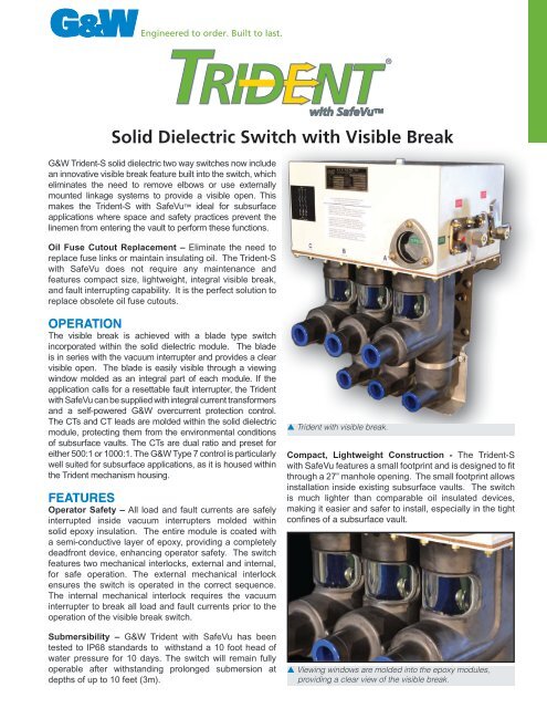
<strong>Solid</strong> <strong>Dielectric</strong> <strong>Switch</strong> <strong>with</strong> <strong>Visible</strong> <strong>Break</strong><br />
G&W Trident-S solid dielectric two way switches now include<br />
an innovative visible break feature built into the switch, which<br />
eliminates the need to remove elbows or use externally<br />
mounted linkage systems to provide a visible open. This<br />
makes the Trident-S <strong>with</strong> SafeVu ideal for subsurface<br />
applications where space and safety practices prevent the<br />
linemen from entering the vault to perform these functions.<br />
Oil Fuse Cutout Replacement – Eliminate the need to<br />
replace fuse links or maintain insulating oil. The Trident-S<br />
<strong>with</strong> SafeVu does not require any maintenance and<br />
features compact size, lightweight, integral visible break,<br />
and fault interrupting capability. It is the perfect solution to<br />
replace obsolete oil fuse cutouts.<br />
OPERATION<br />
The visible break is achieved <strong>with</strong> a blade type switch<br />
incorporated <strong>with</strong>in the solid dielectric module. The blade<br />
is in series <strong>with</strong> the vacuum interrupter and provides a clear<br />
visible open. The blade is easily visible through a viewing<br />
window molded as an integral part of each module. If the<br />
application calls for a resettable fault interrupter, the Trident<br />
<strong>with</strong> SafeVu can be supplied <strong>with</strong> integral current transformers<br />
and a self-powered G&W overcurrent protection control.<br />
The CTs and CT leads are molded <strong>with</strong>in the solid dielectric<br />
module, protecting them from the environmental conditions<br />
of subsurface vaults. The CTs are dual ratio and preset for<br />
either 500:1 or 1000:1. The G&W Type 7 control is particularly<br />
well suited for subsurface applications, as it is housed <strong>with</strong>in<br />
the Trident mechanism housing.<br />
FEATURES<br />
Operator Safety – All load and fault currents are safely<br />
interrupted inside vacuum interrupters molded <strong>with</strong>in<br />
solid epoxy insulation. The entire module is coated <strong>with</strong><br />
a semi-conductive layer of epoxy, providing a completely<br />
deadfront device, enhancing operator safety. The switch<br />
features two mechanical interlocks, external and internal,<br />
for safe operation. The external mechanical interlock<br />
ensures the switch is operated in the correct sequence.<br />
The internal mechanical interlock requires the vacuum<br />
interrupter to break all load and fault currents prior to the<br />
operation of the visible break switch.<br />
Submersibility – G&W Trident <strong>with</strong> SafeVu has been<br />
tested to IP68 standards to <strong>with</strong>stand a 10 foot head of<br />
water pressure for 10 days. The switch will remain fully<br />
operable after <strong>with</strong>standing prolonged submersion at<br />
depths of up to 10 feet (3m).<br />
<strong>with</strong> SafeVu<br />
p Trident <strong>with</strong> visible break.<br />
®<br />
Compact, Lightweight Construction - The Trident-S<br />
<strong>with</strong> SafeVu features a small footprint and is designed to fit<br />
through a 27” manhole opening. The small footprint allows<br />
installation inside existing subsurface vaults. The switch<br />
is much lighter than comparable oil insulated devices,<br />
making it easier and safer to install, especially in the tight<br />
confines of a subsurface vault.<br />
p Viewing windows are molded into the epoxy modules,<br />
providing a clear view of the visible break.
RATINgS<br />
The switch is designed, tested and built per IEEE C37.74 for<br />
load break switching, IEEE C37.60 for fault interrupting, IEEE<br />
386 for bushing specification, and IEC 60529 for environmental<br />
protection rating. Certified test reports are available.<br />
Max System Voltage (kV) 15.5<br />
G&W ELECTRIC PAGE 2<br />
BIL (kV) 95<br />
Continuous Current (A) 630<br />
Peak, asym (kA) 32<br />
Momentary Current, RMS, asym (kA) 20<br />
Making Current, RMS, asym (kA) 20<br />
Interrupting Rating, RMS, sym (kA) 12.5<br />
Short Circuit Current, kA sym, 1<br />
second<br />
12.5<br />
AC Withstand, RMS, Dry, 1 minute (kV) 35<br />
DC Withstand, 15 minutes (kV) 53<br />
Mechanical Operations 2,000<br />
Fault Interrupting Duty per IEEE<br />
C37.60<br />
<strong>Visible</strong><br />
<strong>Break</strong><br />
<strong>Switch</strong><br />
Closed<br />
Submersibility Rating per IP68<br />
Viewing<br />
Window<br />
200A<br />
Deepwell<br />
Bushings<br />
44 operations<br />
at 15-20% rated<br />
interrupting current<br />
56 operations<br />
at 45-55% rated<br />
interrupting current<br />
16 operations at<br />
90-100% rated<br />
interrupting current<br />
10 days under a<br />
10 foot head of<br />
water<br />
31.4”<br />
(797mm)<br />
5.4”<br />
(137mm)<br />
8.6”<br />
(218mm)<br />
Dimensions are approximate.<br />
Approximate weight: 200 lb.<br />
<strong>Visible</strong><br />
<strong>Break</strong><br />
<strong>Switch</strong><br />
Open<br />
24.2”<br />
(614mm)<br />
7.5”<br />
(191mm)<br />
17.3”<br />
(439mm)<br />
<strong>Visible</strong><br />
<strong>Break</strong><br />
<strong>Switch</strong><br />
Vacuum<br />
Bottle
OPTIONS<br />
g&W OvERcURRENT cONTROlS<br />
The overcurrent control monitors the current and sends a<br />
trip signal which opens the vacuum interrupters and interrupts<br />
the fault current. G&W controls are self-powered from<br />
the current transformers located inside the solid dielectric<br />
module. Controls can be equipped to accept a trip input from<br />
a relay or communication device. G&W also offers other<br />
controls, such as SEL relays, depending on the application.<br />
The standard control enclosure for pad mount applications<br />
is fiberglass NEMA 4X (IP56) rated. An optional NEMA 6P<br />
(IP67) rated enclosure is available for applications where<br />
the possibility of flooding or short term submersion is<br />
possible. For vault and subsurface applications, G&W<br />
recommends the Type 7 control. The Type 7 is mounted<br />
<strong>with</strong>in the switch’s mechanism housing and has an IP68<br />
rating for long term submersion.<br />
g&W cONTROl OPTIONS<br />
Type 2 controls provide a user friendly interface for quick<br />
and easy programming. Trip level selections can be made<br />
under load or no-load conditions <strong>with</strong> current ranges in 12<br />
selectable levels. Two ranges of minimum trip settings are<br />
available, 15 to 300 amps and 30 to 600 amps. Each unit is<br />
pre-programmed <strong>with</strong> 30 Time Current Characteristic (TCC)<br />
curves. The curve selection can be set or changed at any<br />
time.<br />
An 8 pole dip switch allows the user to choose the TCC<br />
curve that best matches their specific coordination requirements.<br />
The control can be factory preset to meet the<br />
user’s requirements. As protection or coordination requirements<br />
change, settings can easily be changed in the field.<br />
Pressing the manual trip button when the control is powered<br />
up trips all three phases of the vacuum interrupter. Each<br />
control also includes “Last Cause of Trip” LEDs. These<br />
LEDs indicate which phase experienced an overcurrent<br />
condition, or that<br />
the control was<br />
given an external<br />
or manual trip<br />
command.<br />
Type 2 controls<br />
offer the following<br />
features:<br />
- Three phase<br />
protection<br />
- Minimum trip<br />
set for all three p Type 2 control<br />
phases <strong>with</strong> one<br />
selector switch<br />
- Adjustable phase time delay<br />
- Ground fault (phase imbalance) <strong>with</strong> separate adjustable<br />
time delay selector switch for protection of large three<br />
phase motors or transformers. The ground trip level is<br />
represented as a percent of the minimum trip level.<br />
- Instantaneous trip and inrush restraint features<br />
p Type 3 control<br />
Type 3 and 4 controls provide advanced protection<br />
functions. There are two versions of these controls, each<br />
<strong>with</strong> different protection elements.<br />
The EZset version includes:<br />
- Phase Minimum Trip<br />
- Phase Time Delay<br />
- Phase Instantaneous<br />
- Phase Minimum Response<br />
- Phase Inrush (Cold Load Pickup) Restraint<br />
- Ground Fault (Phase Imbalance) Minimum Trip <strong>with</strong> a<br />
Separate Curve<br />
- 30 Phase/Ground Fault Curves<br />
The Plus version includes all of the above, and in<br />
addition includes:<br />
- Ground Fault Time Delay<br />
- Ground Fault Instantaneous<br />
- Ground Fault Minimum Response<br />
- Ground Fault Inrush (Cold Load Pickup) Restraint<br />
- 60 Phase/ Ground Fault Curves including 5 User<br />
Creatable Curves<br />
- Maintenance Setting Group<br />
The Type 3 and 4 controls record the most recent 16<br />
Cause of Trip Events. The Type 3 includes a display and<br />
keypad for entering programming parameters and viewing<br />
the Cause of Trip Events. The Type 3 Plus, and Type 4<br />
EZset and Plus utilize a notebook computer programming<br />
kit to enter the settings. The notebook computer programming<br />
kit can also be used to download and store the<br />
settings and Cause of Trip Events.<br />
Type 7 controls provide<br />
the same features and<br />
options as the Type 3 and<br />
4 controls, except that<br />
the controls are mounted<br />
<strong>with</strong>in the switch mechanism<br />
housing, eliminating<br />
the need for a separate<br />
control enclosure and<br />
associated cabling. The<br />
control is programmed p Type 7 control programming port<br />
using a notebook computer.<br />
A notebook computer programming kit is available.<br />
G&W ELECTRIC PAGE 3
OPTIONS cONTINUEd<br />
PROgRAmmINg KIT<br />
For Type 3, Type 4 or Type 7<br />
Provides software and cable connection to a notebook<br />
computer for programming or retrieving fault interrupter<br />
control information. The cable connects the USB port of<br />
the computer to the control box (Type 3 or 4) or mechanism<br />
housing (Type 7).<br />
Catalog Number for Type 3, Type 4, Type 7: LPK7-VICSS<br />
p Programming Kit<br />
OThER cOmPATIblE RElAyS FOR OvERcURRENT<br />
PROTEcTION<br />
Various other relays can be provided <strong>with</strong> Trident switchgear<br />
including Schweitzer’s model SEL Falcon, SEL-351R,<br />
SEL-651R, SEL-501, SEL-551, SEL-351S and SEL-751A.<br />
JUNcTION bOx<br />
For auxiliary contacts and remote power/remote trip connections.<br />
Includes NEMA 4X (IP56) enclosure <strong>with</strong> terminal strip<br />
connections.<br />
p Junction Box<br />
G&W ELECTRIC PAGE 4<br />
gROUNd lUgS<br />
Bronze, eyebolt style ground lugs are available for 4/0<br />
maximum conductor cable.<br />
p Ground lug<br />
FRAmES<br />
Bolted, galvanized mounting frames are available for<br />
vertical mounting of vault style switches providing a 24”<br />
distance from the ground to the center of the bottom bushing.<br />
Other size frames are available.<br />
Consult your G&W representative for availability.<br />
bUShINgS<br />
Bushings shall be tested to IEEE 386. The switch is available<br />
<strong>with</strong> either 600A apparatus bushings or 200A deep<br />
well bushings. 600A apparatus bushings are suitable for<br />
use <strong>with</strong> T-body elbows. 200A deep well bushings can be<br />
used <strong>with</strong> 200A load break inserts and elbows.<br />
AUxIlIARy cONTAcTS<br />
Auxiliary contacts are mounted <strong>with</strong>in the mechanism<br />
housing to provide remote indication of the vacuum<br />
interrupter contact position. One normally open and one<br />
normally closed Form C contact is provided.
®<br />
hOW TO ORdER - TRIdENT WITh SAFEvU SWITchgEAR FOR lOAd bREAK APPlIcATIONS<br />
Fill in the spaces using the tables below to build your G&W catalog number:<br />
1<br />
Mounting<br />
Configuration*<br />
Voltage Class<br />
Number of Phases<br />
Description Code<br />
Padmount, front access, vertical mount P<br />
Padmount, front access, horizontal mount H<br />
Dry Vault (equipment room) <strong>with</strong><br />
non-submersible electronics<br />
Subsurface style <strong>with</strong> submersible electronics W<br />
2<br />
3<br />
4<br />
_ A 1 3 - SV L _ _<br />
1 2 3 4 5 6 7 8<br />
Description Code<br />
Bushings front; side mounted handle A<br />
kV Code<br />
15 1<br />
Phase Code<br />
Three 3<br />
V<br />
5<br />
6<br />
7<br />
8<br />
<strong>Switch</strong> Style<br />
Controls<br />
Description Code<br />
Trident-S <strong>with</strong> SafeVu SV<br />
Description Code<br />
Load break switch L<br />
Pre-engineered control; Relay, IED, RTU E<br />
Options<br />
Applicable One-line<br />
Customer supplied control W<br />
Description Code<br />
No options 0<br />
Auxiliary contacts<br />
(vacuum load break switch only)<br />
Custom engineered 4<br />
Bushing Arrangement<br />
<strong>Visible</strong><br />
<strong>Break</strong> switch<br />
Vacuum<br />
Load <strong>Break</strong><br />
switch<br />
Description Code<br />
200A 2<br />
600A 6<br />
G&W ELECTRIC PAGE 5<br />
1
®<br />
hOW TO ORdER - TRIdENT WITh SAFEvU SWITchgEAR FOR FAUlT INTERRUPTINg APPlIcATIONS<br />
Fill in the spaces using the tables below to build your G&W catalog number:<br />
1<br />
Mounting 6 Controls<br />
Configuration*<br />
Voltage Class<br />
Number of Phases<br />
Description Code<br />
Bushings front; side mounted handle A<br />
<strong>Switch</strong> Style<br />
Description Code<br />
Padmount, front access, vertical mount P<br />
Padmount, front access, horizontal mount H<br />
Dry Vault (equipment room) <strong>with</strong><br />
non-submersible electronics<br />
Subsurface style <strong>with</strong> submersible electronics W<br />
2<br />
3<br />
4<br />
5<br />
_ A 1 3 - SV _ _<br />
1 2 3 4 5 6 7 8<br />
kV Code<br />
15 1<br />
Phase Code<br />
Three 3<br />
Description Code<br />
Trident-S <strong>with</strong> SafeVu SV<br />
V<br />
Description Code<br />
Type 2 2<br />
Type 3 EZSet 3E<br />
Type 3 Plus 3P<br />
Type 4 EZSet 4E<br />
Type 4 Plus 4P<br />
Type 7 EZSet 7E<br />
Type 7 Plus 7P<br />
Pre-engineered control; Relay, IED, RTU E<br />
Provisions for future use (includes junction box<br />
<strong>with</strong> CT and trip connections)<br />
7<br />
Options<br />
Description Code<br />
No options 0<br />
Auxiliary contacts (vacuum fault interrupter only) 1<br />
8<br />
Applicable One-line<br />
Custom engineered 4<br />
Bushing Arrangement<br />
Description Code<br />
200A 2<br />
600A 6<br />
G&W <strong>Electric</strong> Company • 305 W. Crossroads Pkwy • Bolingbrook, IL 60440 USA • 708.388.5010 • Fax 708.388.0755 • gwelec.com<br />
Catalog TSV, October 2012<br />
)<br />
<strong>Visible</strong><br />
<strong>Break</strong> switch<br />
Vacuum<br />
Fault<br />
Interrupter<br />
P