rt3 straight-blade snowplow assembly installation ... - Boss Products
rt3 straight-blade snowplow assembly installation ... - Boss Products
rt3 straight-blade snowplow assembly installation ... - Boss Products

Create successful ePaper yourself
Turn your PDF publications into a flip-book with our unique Google optimized e-Paper software.
Snowplow Assembly Procedure<br />
NOTE: This manual is used for the <strong>assembly</strong> of all<br />
BOSS Straight Blade Plows. Part Numbers and<br />
Illustrations may vary. Part numbers for all <strong>Boss</strong><br />
Straight Blade plows are listed on the parts diagram in<br />
this manual.<br />
Figure 1. Shoe Assembly G10059<br />
1) Place Plow Blade (4) on the ground face down.<br />
2) Install MSC01501 Outer Plow Shoe Assembly<br />
(12). Mount Plow Shoes (12B) on Blade Assembly<br />
(4) using eighteen 1” Flat Washers (12C) on the<br />
bottom of shoe and eleven 1” Flat Washers (12C)<br />
on top of the shoe. Secure with 7/16” Quick Pins<br />
(12).<br />
Note: Adjustment of Plow Shoe (12B) may be<br />
necessary after mounting the plow on to the vehicle.<br />
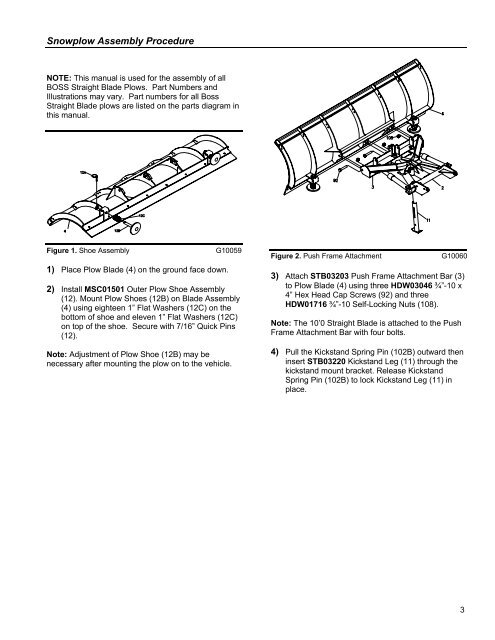
Figure 2. Push Frame Attachment G10060<br />
3) Attach STB03203 Push Frame Attachment Bar (3)<br />
to Plow Blade (4) using three HDW03046 ¾”-10 x<br />
4” Hex Head Cap Screws (92) and three<br />
HDW01716 ¾”-10 Self-Locking Nuts (108).<br />
Note: The 10’0 Straight Blade is attached to the Push<br />
Frame Attachment Bar with four bolts.<br />
4) Pull the Kickstand Spring Pin (102B) outward then<br />
insert STB03220 Kickstand Leg (11) through the<br />
kickstand mount bracket. Release Kickstand<br />
Spring Pin (102B) to lock Kickstand Leg (11) in<br />
place.<br />
3