Skid Steer Combo Plow Owner's Manual - Boss Products
Skid Steer Combo Plow Owner's Manual - Boss Products
Skid Steer Combo Plow Owner's Manual - Boss Products

Create successful ePaper yourself
Turn your PDF publications into a flip-book with our unique Google optimized e-Paper software.
A DIV. OF NORTHERN STAR INDUSTRIES, INC.<br />
P.O. BOX 788 IRON MOUNTAIN, MICHIGAN 49801<br />
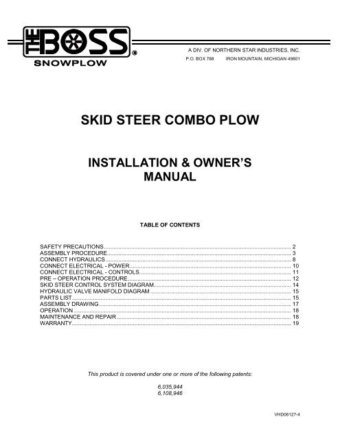
SKID STEER COMBO PLOW<br />
INSTALLATION & OWNER’S<br />
MANUAL<br />
TABLE OF CONTENTS<br />
SAFETY PRECAUTIONS..................................................................................................................... 2<br />
ASSEMBLY PROCEDURE................................................................................................................... 3<br />
CONNECT HYDRAULICS.................................................................................................................... 8<br />
CONNECT ELECTRICAL - POWER..................................................................................................... 10<br />
CONNECT ELECTRICAL - CONTROLS............................................................................................... 11<br />
PRE – OPERATION PROCEDURE...................................................................................................... 12<br />
SKID STEER CONTROL SYSTEM DIAGRAM...................................................................................... 14<br />
HYDRAULIC VALVE MANIFOLD DIAGRAM ........................................................................................ 15<br />
PARTS LIST......................................................................................................................................... 15<br />
ASSEMBLY DRAWING........................................................................................................................ 17<br />
OPERATION........................................................................................................................................ 18<br />
MAINTENANCE AND REPAIR............................................................................................................. 18<br />
WARRANTY......................................................................................................................................... 19<br />
This product is covered under one or more of the following patents:<br />
6,035,944<br />
6,108,946<br />
VHD06127-4
Safety Precautions<br />
Note: Accidents involving machine operation can be avoided by following basic rules and precautions.<br />
All warnings and precautions cited in your skid steer owner’s manual should be carefully observed.<br />
In addition, be sure to adhere to the following precautions.<br />
1) Do not attempt to start the skid steer engine while standing beside the skid steer. Always start the<br />
engine while sitting in the operator’s seat.<br />
2) Always stop the engine when leaving the skid steer.<br />
3) Do not allow anyone but the operator to ride on the skid steer.<br />
4) Do not perform any maintenance or make any adjustments while the skid steer is in motion, the<br />
engine is running, or the plow is raised.<br />
5) Do not attempt to repair or tighten hydraulic hoses when under pressure, when the engine is running,<br />
or when the plow is raised.<br />
6) Do not dismount from the skid steer and leave the plow raised.<br />
7) Do not get under the plow when it is raised.<br />
8) When parking, assure that the plow is fully lowered and the parking brake is set.<br />
9) Exercise extreme caution when operating the skid steer with the plow on the sides of a hill.<br />
10) Do not exceed 6 miles per hour when plowing. Contacting fixed objects at greater speeds may cause<br />
damage to the skid steer and plow, and personal injury may occur.<br />
11) When transporting the plow, keep it as close to the ground as possible without touching and put the<br />
wings back in the vee position.<br />
12) Wear eye protection when operating the plow. Debris may be thrown back toward the operator.<br />
13) Do not use tilt locking pin with power tilt option.<br />
14) Your skid steer should have a relief valve installed in one of the working ports. This will allow an<br />
extended cylinder to collapse when an impact causes excessive pressure in the cylinder’s base end.<br />
BOSS <strong>Products</strong> / Northern Star Industries, Inc. reserves the right under its continuous product<br />
improvement policy to change construction or design details and furnish equipment when so altered<br />
without reference to illustrations or specifications used herein.<br />
2
<strong>Skid</strong> <strong>Steer</strong> <strong>Combo</strong> <strong>Plow</strong> Assembly<br />
Note: The T-frame, T-center, rear mount, and blades each weigh between 150 and 250 lbs. Mechanical<br />
assistance and special care must be used to avoid injury when lifting or moving these assemblies.<br />
1) Unpack<br />
a) Remove the blades and cutting edges from the blade crate.<br />
b) Remove the T-frame, T-center, rear mount, bags and other parts from the plow box and organize<br />
their contents by referencing the packing list.<br />
2) Assemble rear mount<br />
Figure 1<br />
Note: The rear mount is adjustable from 0” to 6” in 2” increments (see Fig. 1). This is to provide flexibility<br />
for installation on different types of vehicles. The preferred height adjustment is 0” but vehicles with<br />
an enclosed cab may require a greater offset so that the vehicle’s arms can be completely lowered.<br />
a) Assemble the adapter plate assembly to the mount frame assembly using the ½ x 1 ½ “ bolts, ½”<br />
nuts and ½” washers provided.<br />
3) Assemble T-frame to rear mount.<br />
Figure 2<br />
a) Support the rear of the T-frame with blocks so that the T-frame is level. The blocks must be<br />
sturdy and stable because they will also be supporting the rear mount when this step is complete.<br />
3
Figure 3<br />
b) Put a 4”OD washer on the clevis pin, and slide the clevis pin through from front to back.<br />
c) Lift the rear mount onto the clevis pin and slide it into contact with the T-frame.<br />
d) Put another 4” OD washer on the backside and secure it with the 3” roll pin.<br />
Figure 4<br />
e) Raise one side of the rear mount until the hole in the rear mount is aligned with the slot of the Tframe<br />
plate. Insert a 1”-8 x 2-1/2” long bolt through a 2-1/2” OD washer, through the slot of the Tframe<br />
plate, and through the hole in the rear mount.<br />
f) Put a 2”OD washer and a 1”-8 locknut on the bolt and hand-tighten the nut.<br />
g) Repeat steps “e” and “f” for the other hole near the top of the plate.<br />
h) Repeat steps “e” and “f” with a 2” OD washer on the front (instead of a 2 ½”OD washer) for the<br />
hole near the bottom of the plate.<br />
i) Torque all three nuts to 30 ft-lbs. The plates should be snug but able to turn against each other.<br />
Do not over-tighten because the power tilt or float will be impaired.<br />
4
4) Assemble T-center to T-frame<br />
Figure 5<br />
a) Position the T-center pivot bushings in line with the T-frame pivot bushing. Connect the two with<br />
a horizontal pin and secure with a 1/4” quick pin.<br />
a) Rotate the T-center to meet the T-frame stop plate and insert a horizontal pin. Secure the pin<br />
with a 1/4” quick pin. Locking out the trip function of the plow during assembly will prevent<br />
accidental rotation of the T-center and possible injury.<br />
5) Attach Blades to T-frame<br />
Figure 6<br />
a) Remove the grease fitting from the center hinge pin.<br />
b) Stand the right and left blade assemblies on their cutting edges oriented as they will be mounted.<br />
c) Raise the front of the T-frame assembly using some mechanical means (e.g. a floor jack) so that<br />
the top of the bottom plate is just beneath the bottom bushing on the right blade assembly.<br />
5
d) Slide the right blade assembly onto the T-frame until the holes are lined up.<br />
e) Slide the left blade assembly on top of the right blade assembly, again being careful to align the<br />
holes.<br />
f) Being sure that the holes are aligned, drive the center hinge pin through the bushings. If the<br />
bushings are properly aligned, it won’t take much effort to position the pin. A block of wood or a<br />
brass pin should be placed over the hinge pin when pounding to protect the internal threads for<br />
the grease fitting.<br />
g) Secure the pin with a 3/8” lock washer and 3/8” x 3/4” hex head cap screw.<br />
h) Replace the grease fitting onto the center hinge pin.<br />
Figure 7<br />
i) Mount the adjustable blade shoe assemblies on each blade assembly. Use the 1” flat washers to<br />
achieve the desired blade height relative to the cutting edges, and secure with the quick pins.<br />
j) Mount the adjustable center shoe assembly onto the center hinge assembly. Use the 1” flat<br />
washers to achieve the desired height relative to the cutting edges, and secure with a quick pin.<br />
Figure 8<br />
k) Mount snow catcher to the center hinge pin using the snow catcher mounting plate, 3/8” lock<br />
washer, and 3/8”-16 x 1 1/4” hex head cap screw. Line up the rear hole in the snow catcher with<br />
the threaded hole in the bottom plate of the T-center assembly and attach using the 3/8”-16 x 3/4”<br />
spin-lock head screw and 3/8” flat washer provided.<br />
6
6) Mount Cylinders<br />
Figure 9<br />
a) Position the base end of the angle cylinders into the T-frame mount, and fasten securely with a<br />
5/8” x 4” hex head bolt and self-locking nut.<br />
b) Position the rod end of the angle cylinders into the blade assemblies, and fasten securely with a<br />
5/8” x 4” hex head bolt and self-locking nut.<br />
7) Install Optional Tilt Package<br />
a) Position the base end of the tilt cylinder in the upper tilt cylinder bracket, and fasten securely with<br />
a 5/8” x 5” hex head bolt and self-locking nut.<br />
b) Position the rod end of the tilt cylinder into the lower tilt cylinder bracket, and fasten securely with<br />
a 5/8” x 3 1/2” hex head bolt and self-locking nut.<br />
c) The hydraulic manifold should already be installed underneath the cover. Remove it.<br />
d) Remove the three hex head o-ring plugs.<br />
e) Install a .035” orifice, valve spool, and solenoid into the spool cavity. Tighten the cartridge to 30-<br />
40 ft-lbs of torque and the coil nut to 4-6 ft-lbs of torque.<br />
f) Replace the manifold.<br />
8) Install trip springs<br />
a) Hook one end of the spring through an anchor on the swivel plate and the other end through a ubolt<br />
on the T-center.<br />
b) Tightening the nuts on the u-bolt will increase the tension in the spring.<br />
7
Connect Hydraulics<br />
Figure 10<br />
Note: All of the cylinder and manifold fittings use o-rings to provide a reliable seal. The quick disconnects<br />
use pipe thread. Use a paste type sealer on the pipe threads. Do not use Teflon tape. Do not<br />
over-tighten the fittings. The fittings merely need to be tight enough to prevent leaks. Refer to<br />
Figure 10 for steps a through h.<br />
a) Connect the 90 o -swivel end of a 43” hose to C1 on the manifold and to the rod end of the right<br />
cylinder.<br />
b) Connect the 90 o -swivel end of a 43” hose to C3 on the manifold and to the rod end of the left<br />
cylinder.<br />
c) Connect the 90 o -swivel end of a 27” hose to C2 on the manifold and to the base end of the right<br />
cylinder.<br />
d) Connect the 90 o -swivel end of a 27” hose to C4 on the manifold and to the base end of the left<br />
cylinder.<br />
e) If you are not using the power tilt option, clamp the 43” hose that is attached to the rod end of the<br />
right cylinder to the top plate on the T-Frame. Use the cushioned hose clamp and self-tapping<br />
screw as shown in Figure 11. A pilot hole is provided in the top plate for the self-tapping screw.<br />
Figure 11<br />
Note: Steps f and g apply only to plows with power tilt option. O-ring plugs should be left in ports C5 and<br />
C6 if power tilt is not used.<br />
8
Figure 12<br />
f) Connect the 90 o -swivel end of a 27” hose to C5 on the manifold and to the base end of the tilt<br />
cylinder. Run this hose over the 43” hose that is attached to the rod end of the right cylinder.<br />
g) Connect the 90 o -swivel end of a 27” hose to C6 on the manifold and to the rod end of the tilt<br />
cylinder.<br />
h) Connect 60” hoses to both of the side ports on the manifold, V1 and V2.<br />
i) Attach the quick disconnects (not supplied) to the 3/8” Male NPT coupling at the end of the 60”<br />
hoses. The V2 port on the manifold should be connected to the working port on the skid steer that<br />
has a relief valve installed.<br />
9
Connect Electrical – Power<br />
a) Mount the control box (Ref. 1, Fig. 15) within the vehicle cab. The most appropriate location for<br />
the control will depend on the vehicle, personal preference, and intended use. In general, be<br />
aware of the swing of the seat crash bar and the travel of the vehicle’s arms and tilt of the tool<br />
holder. Assure that there are no interferences, and that the cable won’t be damaged during<br />
operation. Enough cable is provided to run it out of the cab and along the arm. Be sure to leave<br />
enough slack in the cable at the arm’s pivot point. For normal operation, this is the most<br />
desirable arrangement, however, be careful when tilting the cab during maintenance procedures<br />
to avoid damaging the cable or connections. Tie-wraps are provided so that the slack cable can<br />
be kept out of the way.<br />
b) Locate the intermediate connector (Ref. 2, Fig. 15) by the vehicle’s hydraulic disconnects.<br />
c) Various terminals, a fuse holder and fuse are included for making the power connection (See Fig.<br />
14). The red power wire must be fused to protect the wiring in the event of a short or overload.<br />
Never use fuses larger than 20 AMP’s. If a fuse blows, this indicates a problem. Check for a<br />
wiring error or damaged wiring before replacing the fuse.<br />
d) Before installation, check that your electrical system is 12 volts, negative ground. Damage<br />
resulting from improper voltage or ground polarity could be extensive and is not covered under<br />
the warranty.<br />
e) The black power wire is connected to ground. This connection is usually made to the frame of the<br />
vehicle using a ring terminal under a bolt or screw. Scrape the paint off the contact surface, metal<br />
to metal contact is needed to insure a proper ground. The engine block or battery ground terminal<br />
are also good locations for a ground connection.<br />
f) The red power wire connects to the 12-volt power supply. This connection should be made in a<br />
location that is controlled by the ignition key to prevent the battery from being drained in the event<br />
the switch is left on. Look on the fuse panel for a terminal marked IGN or use a test light to find a<br />
fuse that that has power only when the key is on. Connect the red wire to the IGN terminal or use<br />
one of the fuse tap terminals (See Fig. 14) to connect to the hot end of a fuse that is controlled by<br />
the ignition key. This should be a 20 AMP or larger fuse. Remove the fuse and use the test light<br />
to determine which end of the fuse holder is hot with the fuse removed and connect to this end.<br />
Use a female blade terminal on the end of the red wire to connect to the fuse tab. Another way to<br />
obtain power is to use the “half-tap” connector (this looks like a half of an in-line fuse holder<br />
shown in Figure 14), which snaps around a hot wire. Use a male blade terminal on the red wire to<br />
connect to the “half-tap”.<br />
g) After making the power connection, cut the red wire a short distance from the power connection<br />
and reconnect the ends together using the fuse holder. Insert the two ends of the wire into the<br />
fuse holder snapping it closed, and then insert the fuse.<br />
Figure 13<br />
10
Connect Electrical – Control<br />
a) Snap the male connectors (Ref. 3, Fig. 15) at the end of the control box wiring harness into the<br />
female connectors located on the manifold solenoids. The wires on the male connectors are<br />
color-coded and should be connected to the corresponding female connector (as shown in Figure<br />
18). Depending on how you’ve mounted the control box (Ref. 1, Fig. 15) and how you make the<br />
connections, you may want to adjust these connections after testing them. In order from left to<br />
right, the toggle switches usually correspond to left wing, tilt, and right wing.<br />
b) Use the tie wraps to fix the wire in place. The wire should be secured so that the leads going into<br />
the connector are protected from accidental tightening of the wire harness. Enough wire is<br />
provided to allow the plow to be tilted or to float fully in both directions. Be sure to consider this<br />
before cutting the wire and installing the intermediate connector (Ref. 2, Fig. 15).<br />
ITEM NO. QUANTITY PART NO. DESCRIPTION<br />
1 1 VHD06947 CONTROL BOX<br />
2 1 VHD06948 INTERMEDIATE CONNECTOR<br />
3 3 VHD06949 MALE SOLENOID CONNECTORS<br />
FIG. 14 1 VHD06946 CONTROL KIT<br />
Figure 14<br />
11
Before Operating<br />
1) Lubrication<br />
Figure 15<br />
a) Apply grease to the fitting at the top of the center hinge pin. The grease must travel all of the way<br />
to the bottom of the pin to be completely effective. Be sure that you continue to add grease until<br />
you see it escaping near the bottom bushing.<br />
b) Apply grease to the three fittings on the T-Frame back plate. Be sure to add grease until you can<br />
see it begin to seep out of the seam between the two plates.<br />
2) Attach the plow using the procedure recommended by your skid steer owner’s manual.<br />
3) Connect the hydraulic quick disconnects.<br />
12
4) Tilt Lock<br />
Figure 16<br />
a) The coupler spring pin is provided to lock out the tilt action on plows without the power tilt option.<br />
When plowing snow, the free-floating tilt action of the plow is desirable. However, certain<br />
applications may require the plow to be locked into a horizontal position. Also, locking out the tilt<br />
during plow assembly or service will prevent accidental rotation of the plow or rear mount.<br />
b) To lock out the tilt, insert the coupler spring pin through the 3 ears on the T-Frame until it fully<br />
engages the swivel plate on the rear mount. Lock the pin in place with the #9 hairpin cotter<br />
provided. The hairpin should be between the 2 rear-most ears on the T-Frame. To unlock the tilt,<br />
remove the hairpin and pull out the coupler spring pin until its hole is visible between the 2 frontmost<br />
ears on the T-Frame. Replace the hairpin.<br />
13
<strong>Skid</strong> <strong>Steer</strong> <strong>Combo</strong> <strong>Plow</strong> Valve Manifold<br />
ITEM NO. QUANTITY PART NO. DESCRIPTION<br />
1 1 * MANIFOLD BLOCK<br />
2 2 VHD06995 RELIEF VALVE<br />
3 1 VHD06996 ORIFICE DISK WITH .035” DIA. HOLE<br />
4 2 VHD06997 ORIFICE DISK WITH .086” DIA. HOLE<br />
5 3 VHD06994 VALVE SPOOL<br />
6 3 VHD06993 SOLENOID WITH DELPHI CONNECTOR<br />
7 3 NA ½ – 20 UNF NUT<br />
<strong>Skid</strong> <strong>Steer</strong> <strong>Combo</strong> <strong>Plow</strong> Parts List<br />
Figure 17<br />
REF. NO. PART NO. DESCRIPTION<br />
1 VHD06700 7’ 6” SKID STEER RIGHT BLADE ASSEMBLY<br />
1 VHD06613 5’ 5” SKID STEER RIGHT BLADE ASSEMBLY<br />
2 VHD06600 7’ 6” SKID STEER LEFT BLADE ASSEMBLY<br />
2 VHD06612 5’ 5” SKID STEER LEFT BLADE ASSEMBLY<br />
3 VHD06110 COMBO T-CENTER ASSEMBLY<br />
15<br />
G10158
4 VHD06980 COMBO T-FRAME ADAPTER ASSEMBLY<br />
5 VHD06870 MOUNT FRAME ASSEMBLY<br />
6 VHD06661 CUTTING EDGE 5/8” x 6” FOR 7’-6” BLADE<br />
6 VHD06662 CUTTING EDGE 5/8” x 6” FOR 5’-5” BLADE<br />
7 VHD06128 CARRIAGE BOLTS WITH NUTS (SET OF 10)<br />
8 VHD06963 HYDRAULIC MANIFOLD WITH TILT CARTRIDGE<br />
8 VHD06901 HYDRAULIC MANIFOLD NO TILT CARTRIDGE<br />
9 VHD06966 5/16” x 2 ¾” HEX HEAD BOLT<br />
10 VHD06967 5/16” FLAT WASHER<br />
11 VHD06139 5/16” NYLON SELF LOCKING NUT<br />
12 VHD06502 CENTER HINGE PIN<br />
13 VHD06992 3/8” x ¾” HEX HEAD CAP SCREW<br />
14 VHD01718 3/8” LOCK WASHER<br />
15 VHD06511 1/8” NPT GREASE FITTING<br />
16 VHD06111 TRIP SPRING<br />
17 VHD06112 1/2” SST U-BOLT<br />
18 VHD06125 1/2” NYLON LOCK NUT<br />
21 VHD06953 HORIZONTAL PIN<br />
22 VHD06148 1/4” QUICK PIN<br />
23 VHD06814 CLEVIS PIN<br />
24 VHD07232 CLEVIS PIN WASHER<br />
25 VHD06510 3/8” x 3” LONG ROLL PIN<br />
26-27-20 VHD06149 PLOW SHOE (1” SHAFT)<br />
(20) 1” FLAT WASHERS<br />
7/16” QUICK PIN<br />
28-27-20 VHD06150 CAST IRON PLOW SHOE (1” SHAFT)<br />
(20) 1” FLAT WASHERS<br />
7/16” QUICK PIN<br />
29 VHD06507 1” x 2 ½” HEX HEAD BOLT<br />
30 VHD06509 1”ID x 2”OD FLAT WASHER<br />
31 VHD06822 1”ID x 2 ½”OD FLAT WASHER<br />
32 VHD06508 1” OVAL TOP LOCK NUT<br />
33 VHD06130 5/8” x 4” HEX HEAD BOLT<br />
34 VHD06133 5/8” SELF LOCKING NUT<br />
35 VHD06153 5/8” x 5” HEX HEAD BOLT<br />
36 VHD06902 2 ¼” x 10” DOUBLE ACTING CYLINDER<br />
37 VHD06962 2 ¼” x 6 ¼” DOUBLE ACTING CYLINDER<br />
38 VHD06998 06RC x 06RC90 3/8” x 27” HOSE<br />
39 VHD06906 06RC x 06RC90 3/8” x 43” HOSE<br />
40 VHD06905 06RC x 08MP 3/8” x 60” HOSE<br />
-- VHD06946 CONTROL KIT<br />
-- VHD06947 CONTROL BOX<br />
-- VHD06948 INTERMEDIATE CONNECTOR<br />
-- VHD06949 SOLENOID CONNECTOR<br />
41 VHD06152 SNOW CATCHER<br />
42 VHD06141 3/8 – 16 x 1” HEX HEAD CAP SCREW<br />
43 VHD06144 3/8” FLAT WASHER<br />
44 VHD06146 3/8 – 16 x 1 1/4” HEX HEAD CAP SCREW<br />
45 VHD06151 SNOW CATCHER MOUNTING PLATE<br />
46 VHD06869 ADAPTER PLATE ASSEMBLY<br />
47 VHD06143 ½ - 13 x 1 ½” HEX HEAD BOLT<br />
48 VHD06147 ½” FLAT WASHER<br />
49 VHD06145 ½” –13 SELF LOCKING NUT<br />
50 VHD06142 3/8” LOCK WASHER<br />
51 VHD06129 COUPLER SPRING PIN<br />
52 VHD06512 #9 HAIRPIN COTTER<br />
53 VHD06154 HOSE CLAMP, 5/8” W/RUBBER CUSHION<br />
54 VHD06155 SELF TAPPING SCREW, ¼” – 20 x ¾”<br />
16
<strong>Skid</strong> <strong>Steer</strong> <strong>Combo</strong> <strong>Plow</strong> Assembly Drawing<br />
Figure 17<br />
17
Operation<br />
Refer to the owner’s manual supplied by your skid steer manufacturer for instructions on how to<br />
operate the vehicle’s auxiliary hydraulics. In general, the auxiliary hydraulics should be on but not<br />
locked. The skid steer controls can then be used to intermittently control the presence and direction of<br />
the flow. The supplied toggle-switch control selects the circuit within the plow through which the oil<br />
will pass.<br />
1) To actuate one of the plow cylinders, simply move its toggle switch on the control box until the<br />
indicator light comes on.<br />
2) That cylinder can now be extended or retracted by using your vehicle’s auxiliary hydraulics control as<br />
described in your vehicle owner’s manual.<br />
3) <strong>Plow</strong>ing Tips<br />
The following table illustrates the preferred toggle switch settings for various plowing situations.<br />
LEFT TILT RIGHT<br />
OPERATION SUGGESTED<br />
WING<br />
WING<br />
USE<br />
ON OFF OFF MOVE LEFT WING ONLY USE FOR PLOWING<br />
NA ON NA TILT BLADE USE FOR PLOWING<br />
OFF OFF ON MOVE RIGHT WING ONLY USE FOR PLOWING<br />
ON OFF ON MOVE BOTH WINGS IN THE<br />
SAME DIRECTION<br />
18<br />
NOT RECOMMENDED FOR<br />
PLOWING UNLESS IN EITHER THE<br />
SCOOP OR VEE POSITION<br />
When tilting the plow, neither of the wing circuits should be active. Therefore, those circuits are disabled<br />
when the tilt circuit is activated. If plowing is performed with more than one circuit active, the plowing force<br />
may cause a cylinder to retract, and the displaced oil will cause another cylinder to extend. This<br />
inadvertent cylinder movement will not occur if the plow is in either the scoop or vee positions. In<br />
addition, it won’t occur if only one circuit is active.<br />
The power tilt is primarily intended for light grading operations. When plowing snow, the free-floating<br />
action of the plow without the tilt cylinder is more desirable. To achieve this it is recommended that the tilt<br />
circuit be removed completely and the manifold ports be plugged.<br />
CAUTION<br />
Exercise caution when tilting the skid steer tool carrier. The plow supply hoses and electrical wire<br />
are sufficiently long for any plowing configuration, but they may be damaged if the tool carrier is<br />
moved to an extreme forward tilt position.<br />
Maintenance and Repair<br />
1) The grease fittings should be lubricated frequently, especially when working in dirt.<br />
2) Repair hydraulic oil leaks promptly to avoid contamination to the hydraulic system.<br />
3) Check all bolts periodically and tighten if necessary.<br />
4) Regularly inspect the plow and repair or replace any worn or damaged parts.
BOSS SNOWPLOW LIMITED<br />
CONSUMER WARRANTY<br />
What the warranty covers:<br />
BOSS PRODUCTS warrants to the original retail purchaser of a BOSS snowplow who purchases it for<br />
personal, family or household use, that the snowplow will be free from defects in material and<br />
workmanship except as set forth below.<br />
Warranty period:<br />
Parts: One year from the date of purchase.<br />
Labor: One year from the date of purchase.<br />
What BOSS PRODUCTS will do:<br />
If, within the warranty period, the snowplow is found to be defective, BOSS PRODUCTS will repair or<br />
replace, at its sole option, the defective parts at no charge to the original purchaser.<br />
What you must do for warranty service:<br />
To obtain service under this warranty, purchaser must return the defective snowplow to an authorized<br />
BOSS PRODUCTS dealer (preferably the one from whom the snowplow was purchased). The purchaser<br />
must establish the warranty period by verifying the original purchased date. All transportation costs to<br />
and from the dealer will be the responsibility of the purchaser. To locate the authorized BOSS dealer<br />
nearest to you, call toll free: (800) 286-4155.<br />
What is not covered:<br />
This limited warranty does not cover the following:<br />
1. Expendable parts such as hoses, plow shoes, cutting edges, pins, nuts, bolts, blade guides, etc.<br />
2. Snowplows or parts repaired or altered by anyone other than an authorized BOSS PRODUCTS<br />
dealer.<br />
3. Snowplows or parts which have been subject to misuse or service, negligence, accident, improper<br />
installation, maintenance, care or storage.<br />
4. Snowplows mounted on vehicles other than those listed in the BOSS SNOWPLOW APPLICATION<br />
CHART AND SELECTION GUIDE.<br />
5. BOSS PRODUCTS does not assume any liability for motor vehicle damage resulting from the<br />
attachment or use of a BOSS PRODUCTS snowplow. Vehicle risk is the sole responsibility of the<br />
purchaser.<br />
Warranty limitations:<br />
THIS WARRANTY IS OFFERED IN LIEU OF ANY OTHER EXPRESS WARRANTY.<br />
THE DURATION OF ALL IMPLIED WARRANTIES, INCLUDING BUT NOT LIMITED TO THE<br />
IMPLIED WARRANTIES OF MERCHANTABILITY AND FITNESS FOR A PARTICULAR<br />
PURPOSE, ARE LIMITED TO THE DURATION OF THIS WARRANTY.<br />
BOSS PRODUCTS LIABILITY IS EXPRESSLY LIMITED TO THE REPAIR OF THE SNOWPLOW,<br />
INCLUDING LABOR AND REPLACEMENT OF DEFECTIVE PARTS. BOSS PRODUCTS SHALL<br />
NOT BE LIABLE FOR ANY CONSEQUENTIAL, INCIDENTAL OR CONTINGENT DAMAGES<br />
WHATSOEVER, EVEN IF DAMAGES ARE CAUSED BY BOSS PRODUCTS NEGLIGENCE OR<br />
FAULT.<br />
State laws:<br />
Some states do not allow exclusion of incidental or consequential damages or the limitations on how long<br />
an implied warranty lasts, so these limitations or exclusions may not apply to you. This warranty gives<br />
you specific legal rights and you may also have the other rights which vary from state to state.<br />
This warranty does not apply if you purchased your snowplow for other than personal, family, or household use. If<br />
so, refer to the BOSS Snowplow Commercial Warranty.<br />
BOSS PRODUCTS is a division of<br />
Northern Star Industries, Inc.<br />
PO Box 788<br />
North U.S. Hwy 2<br />
4/01 (2001-2002) Iron Mountain, MI 49801<br />
19
BOSS SNOWPLOW<br />
COMMERCIAL WARRANTY<br />
What this warranty covers:<br />
This warranty covers defects in material and workmanship except as set forth below.<br />
Who is covered:<br />
The original purchaser from an authorized dealer.<br />
For how long:<br />
Parts: One year from the date of purchase.<br />
Labor: One year from the date of purchase.<br />
What BOSS PRODUCTS will do:<br />
BOSS PRODUCTS will, at its sole option, repair or replace defective parts at no charge.<br />
What you must do to for warranty service:<br />
To obtain warranty service, purchaser must return the defective snowplow to any authorized BOSS<br />
PRODUCTS dealer (preferably the one from whom the snowplow was purchased) within the<br />
warranty period. Purchaser must be able to verify the original purchase date. All transportation costs<br />
to and from the dealer will be the responsibility of the purchaser. To locate the authorized BOSS<br />
dealer nearest to you, call toll free: (800) 286-4155.<br />
What is not covered:<br />
This warranty does not cover:<br />
1. Expendable parts such as hoses, plow shoes, cutting edges, pins, nuts, bolts, blade guides, etc.<br />
2. Snowplows or parts repaired or altered by anyone other than an authorized BOSS PRODUCTS<br />
dealer.<br />
3. Snowplows or parts which have been subject to misuse, negligence, accident, improper<br />
installation, maintenance, care or storage.<br />
4. Snowplows mounted on vehicles other than those listed in the BOSS SNOWPLOW<br />
APPLICATION CHART AND SELECTION GUIDE.<br />
5. BOSS PRODUCTS does not assume liability for damage to your motor vehicle resulting from<br />
the attachment or use of a BOSS PRODUCTS snowplow. Vehicle risk is the sole responsibility<br />
of the purchaser.<br />
Limits of BOSS <strong>Products</strong> Liability are:<br />
BOSS PRODUCTS LIABILITY IS EXPRESSLY LIMITED TO REPAIR OR REPLACEMENT<br />
OF DEFECTIVE PARTS. BOSS PRODUCTS SHALL NOT BE LIABLE FOR<br />
CONSEQUENTIAL, INCIDENTAL OR CONTINGENT DAMAGES WHATSOEVER, EVEN IF<br />
DAMAGES ARE CAUSED BY THE NEGLIGENCE OR FAULT OF BOSS PRODUCTS.<br />
THE FOREGOING WARRANTIES ARE EXCLUSIVE AND IN LIEU OF ALL OTHER<br />
EXPRESS AND IMPLIED WARRANTIES INCLUDING, BUT NOT LIMITED TO, THE<br />
IMPLIED WARRANTIES OF MERCHANTABILITY AND FITNESS FOR A PARTICULAR<br />
PURPOSE.<br />
This warranty does not apply if you purchased your snowplow for personal, family, or household<br />
use. In this case, refer to the BOSS Snowplow Limited Consumer Warranty.<br />
BOSS PRODUCTS is a division of<br />
4/01 (2001-2002)<br />
Northern Star Industries, Inc.<br />
PO Box 788<br />
North U.S. Hwy 2<br />
Iron Mountain, MI 49801<br />
20