Skid Steer Combo Plow Owner's Manual - Boss Products
Skid Steer Combo Plow Owner's Manual - Boss Products
Skid Steer Combo Plow Owner's Manual - Boss Products

You also want an ePaper? Increase the reach of your titles
YUMPU automatically turns print PDFs into web optimized ePapers that Google loves.
Connect Electrical – Power<br />
a) Mount the control box (Ref. 1, Fig. 15) within the vehicle cab. The most appropriate location for<br />
the control will depend on the vehicle, personal preference, and intended use. In general, be<br />
aware of the swing of the seat crash bar and the travel of the vehicle’s arms and tilt of the tool<br />
holder. Assure that there are no interferences, and that the cable won’t be damaged during<br />
operation. Enough cable is provided to run it out of the cab and along the arm. Be sure to leave<br />
enough slack in the cable at the arm’s pivot point. For normal operation, this is the most<br />
desirable arrangement, however, be careful when tilting the cab during maintenance procedures<br />
to avoid damaging the cable or connections. Tie-wraps are provided so that the slack cable can<br />
be kept out of the way.<br />
b) Locate the intermediate connector (Ref. 2, Fig. 15) by the vehicle’s hydraulic disconnects.<br />
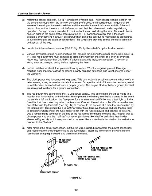
c) Various terminals, a fuse holder and fuse are included for making the power connection (See Fig.<br />
14). The red power wire must be fused to protect the wiring in the event of a short or overload.<br />
Never use fuses larger than 20 AMP’s. If a fuse blows, this indicates a problem. Check for a<br />
wiring error or damaged wiring before replacing the fuse.<br />
d) Before installation, check that your electrical system is 12 volts, negative ground. Damage<br />
resulting from improper voltage or ground polarity could be extensive and is not covered under<br />
the warranty.<br />
e) The black power wire is connected to ground. This connection is usually made to the frame of the<br />
vehicle using a ring terminal under a bolt or screw. Scrape the paint off the contact surface, metal<br />
to metal contact is needed to insure a proper ground. The engine block or battery ground terminal<br />
are also good locations for a ground connection.<br />
f) The red power wire connects to the 12-volt power supply. This connection should be made in a<br />
location that is controlled by the ignition key to prevent the battery from being drained in the event<br />
the switch is left on. Look on the fuse panel for a terminal marked IGN or use a test light to find a<br />
fuse that that has power only when the key is on. Connect the red wire to the IGN terminal or use<br />
one of the fuse tap terminals (See Fig. 14) to connect to the hot end of a fuse that is controlled by<br />
the ignition key. This should be a 20 AMP or larger fuse. Remove the fuse and use the test light<br />
to determine which end of the fuse holder is hot with the fuse removed and connect to this end.<br />
Use a female blade terminal on the end of the red wire to connect to the fuse tab. Another way to<br />
obtain power is to use the “half-tap” connector (this looks like a half of an in-line fuse holder<br />
shown in Figure 14), which snaps around a hot wire. Use a male blade terminal on the red wire to<br />
connect to the “half-tap”.<br />
g) After making the power connection, cut the red wire a short distance from the power connection<br />
and reconnect the ends together using the fuse holder. Insert the two ends of the wire into the<br />
fuse holder snapping it closed, and then insert the fuse.<br />
Figure 13<br />
10