Skid Steer Combo Plow Owner's Manual - Boss Products
Skid Steer Combo Plow Owner's Manual - Boss Products
Skid Steer Combo Plow Owner's Manual - Boss Products

Create successful ePaper yourself
Turn your PDF publications into a flip-book with our unique Google optimized e-Paper software.
d) Slide the right blade assembly onto the T-frame until the holes are lined up.<br />
e) Slide the left blade assembly on top of the right blade assembly, again being careful to align the<br />
holes.<br />
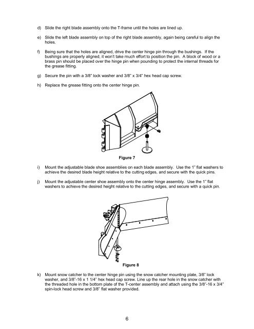
f) Being sure that the holes are aligned, drive the center hinge pin through the bushings. If the<br />
bushings are properly aligned, it won’t take much effort to position the pin. A block of wood or a<br />
brass pin should be placed over the hinge pin when pounding to protect the internal threads for<br />
the grease fitting.<br />
g) Secure the pin with a 3/8” lock washer and 3/8” x 3/4” hex head cap screw.<br />
h) Replace the grease fitting onto the center hinge pin.<br />
Figure 7<br />
i) Mount the adjustable blade shoe assemblies on each blade assembly. Use the 1” flat washers to<br />
achieve the desired blade height relative to the cutting edges, and secure with the quick pins.<br />
j) Mount the adjustable center shoe assembly onto the center hinge assembly. Use the 1” flat<br />
washers to achieve the desired height relative to the cutting edges, and secure with a quick pin.<br />
Figure 8<br />
k) Mount snow catcher to the center hinge pin using the snow catcher mounting plate, 3/8” lock<br />
washer, and 3/8”-16 x 1 1/4” hex head cap screw. Line up the rear hole in the snow catcher with<br />
the threaded hole in the bottom plate of the T-center assembly and attach using the 3/8”-16 x 3/4”<br />
spin-lock head screw and 3/8” flat washer provided.<br />
6