

installation manual - Auton Motorized Systems
installation manual - Auton Motorized Systems
installation manual - Auton Motorized Systems

You also want an ePaper? Increase the reach of your titles
YUMPU automatically turns print PDFs into web optimized ePapers that Google loves.
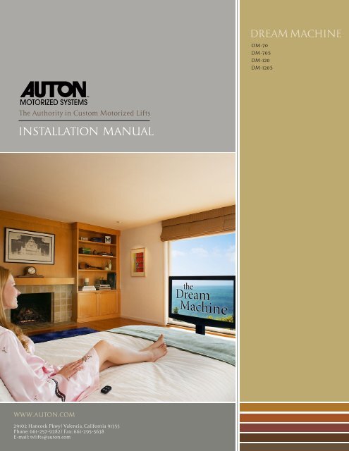
The Authority in Custom <strong>Motorized</strong> Lifts<br />
INSTALLATION MANUAL<br />
WWW.AUTON.COM<br />
29102 Hancock Pkwy | Valencia, California 91355<br />
Phone: 661-257-9282 | Fax: 661-295-5638<br />
E-mail: tvlifts@auton.com<br />
DREAM MACHINE<br />
DM-70<br />
DM-70S<br />
DM-120<br />
DM-120S
The Authority in Custom <strong>Motorized</strong> Lifts<br />
INSTALLATION MANUAL<br />
Dream machine Installation Guide<br />
Step 1: Testing<br />
Please read the <strong>manual</strong> before operating.<br />
Test before Installation<br />
1. Place unit on a hard flat level surface with enough clearance to operate.<br />
2. Remove side handle bars before plugging into power source. The front handles may be<br />
left in place or removed.<br />
3. Plug into an 110V AC convenience outlet.<br />
(A surge protector is highly recommended)<br />
4. Make sure nothing will interfere with it’s operation .<br />
5. Press the UP button on the wireless remote control. The unit will slide out, pivot up and<br />
extend to the full up position. (Units with the swivel options will only swivel once it’s<br />
in the fully extended up position and will only retract when centered)<br />
Caution:<br />
Do Not under any circumstances exceed the recommended weight capacity.<br />
Do Not attempt to modify or alter the unit. Doing so will void your warranty and place the<br />
unit and attached load at risk.<br />
The unit must be installed on a hard flat level surface, if placed on carpet a board with a<br />
minimum thickness of 3/8” must be placed underneath the unit.<br />
Do Not adjust limit on the motor itself unless instructed by one of our technicians, Using a<br />
power tool to adjust the limits will void the warranty.<br />
Installation support:<br />
We take great pride in manufacturing the best lift systems in the world. Our design and production techniques enable simple <strong>installation</strong>.<br />
In the event that you require assistance, do not hesitate to contact one of our technicians. We will be happy to answer your questions and resolve<br />
any problems you encounter during the <strong>installation</strong> process. Phone Support: 661-257-9282, exrt: tech@auton.com<br />
WWW.AUTON.COM<br />
29102 Hancock Pkwy | Valencia, California 91355<br />
Phone: 661-257-9282 | Fax: 661-295-5638<br />
E-mail: tvlifts@auton.com
Step 2: Setting Limits<br />
Setting Up limit<br />
Note:<br />
Up limit has been preset at factory for full travel. Use the hand held programming<br />
switch to set Up limits ONLY if you want to change or adjust the limit setting.<br />
1. Unplug existing “switch lead” from the post’s control box.<br />
2. Plug “programming switch” into control box.<br />
3. Use the “arrows” on the switch to raise the lift to the desired up location.<br />
4. Press “S”, release, and then press “1”. You’ve set the up limit stop.<br />
5. After setting limit stop point, DO NOT use the arrow keys to operate the mechanism.<br />
Press and hold #1 for Up & press and hold #2 for down.<br />
6. Unplug programming switch from control box and replace with original switch lead.<br />
Step 3: Installation<br />
Installation & Setup Instructions<br />
Programming Switch<br />
1. After testing the unit mount the TV to the mounting brackets.<br />
2. Route the power cord and other cables going to the TV through the existing cable guide.<br />
3. Place lift in location. It must be place on a hard level surface (see Caution section).<br />
The unit must be 3/4” - 1” from the end of the bed frame.<br />
(optional) Secure unit to the floor using the 4 pre drilled holes, one on each side of<br />
mounting bracket.<br />
4. Plug the unit to a 110V power source. (A surge protector is highly recommended)<br />
Installation support:<br />
We take great pride in manufacturing the best lift systems in the world. Our design and production techniques enable simple <strong>installation</strong>.<br />
In<br />
the event that you require assistance, do not hesitate to contact one of our technicians. We will be happy to answer your questions and resolve<br />
any problems you encounter during the <strong>installation</strong> process. Phone Support: 661-257-9282, exrt: tech@auton.com<br />
WWW.AUTON.COM<br />
29102 Hancock Pkwy | Valencia, California 91355<br />
Phone: 661-257-9282 | Fax: 661-295-5638<br />
E-mail: tvlifts@auton.com<br />
Switch lead and programming<br />
switch may be plugged in either<br />
port.
Re-Synchronization Process<br />
If for any reason the post(s) doesn’t respond when activated by normal control method<br />
(RF Remote, IR Remote, or Low Voltage Contact Closure) the following procedure will re sync<br />
the telescoping post(s) to the control box.<br />
Be sure to first check power, connections, etc…<br />
With the unit in the extended and up position, do the following:<br />
1. Unplug the existing switch lead from the control box.<br />
2. Plug in the Hand-Held Programming Switch<br />
3. If the lift is fully retracted press and hold the down arrow button until the post(s) ‘bump’<br />
up or down ¼ inch (this may take over a minute). Go to Step 5<br />
4. If the lift is not fully retracted press and hold the down arrow until the post(s) fully<br />
retract (this may take over a minute). Go to step 5<br />
5. Reset the upper limit setting according to the instructions provided on page 3.<br />
6. Unplug the Hand-Held Programming Switch from the control box.<br />
7. Plug in the existing switch lead.<br />
8. Activate the lift.<br />
Installation support:<br />
We take great pride in manufacturing the best lift systems in the world. Our design and production techniques enable simple <strong>installation</strong>.<br />
In the event that you require assistance, do not hesitate to contact one of our technicians. We will be happy to answer your questions and resolve<br />
any problems you encounter during the <strong>installation</strong> process. Phone Support: 661-257-9282, exrt: tech@auton.com<br />
WWW.AUTON.COM<br />
29102 Hancock Pkwy | Valencia, California 91355<br />
Phone: 661-257-9282 | Fax: 661-295-5638<br />
E-mail: tvlifts@auton.com
Control Box<br />
The IR control box comes with two plugs. The 6 pin connects to cable coming out of the<br />
cable management system.<br />
The 3 pin connector connects to the IR<br />
eye cable.<br />
The RF control box comes only with the 6 pin<br />
connector.<br />
Manual Operation<br />
The toggle switch must be moved to the<br />
OFF position to activate the <strong>manual</strong> mode<br />
function. The LED will be OFF.<br />
1) Deploy<br />
2) Retract<br />
Deploy Retract<br />
Common<br />
Move toggle switch to the ON<br />
position to activate the remote<br />
control function. The LED will<br />
be on.<br />
Dry Contact Operation:<br />
Short desired operation with COM<br />
Installation support:<br />
We take great pride in manufacturing the best lift systems in the world. Our design and production techniques enable simple <strong>installation</strong>.<br />
In the event that you require assistance, do not hesitate to contact one of our technicians. We will be happy to answer your questions and resolve<br />
any problems you encounter during the <strong>installation</strong> process. Phone Support: 661-257-9282, exrt: tech@auton.com<br />
WWW.AUTON.COM<br />
29102 Hancock Pkwy | Valencia, California 91355<br />
Phone: 661-257-9282 | Fax: 661-295-5638<br />
E-mail: tvlifts@auton.com