OPERATOR'S MANUAL - Ryobi
OPERATOR'S MANUAL - Ryobi
OPERATOR'S MANUAL - Ryobi

Create successful ePaper yourself
Turn your PDF publications into a flip-book with our unique Google optimized e-Paper software.
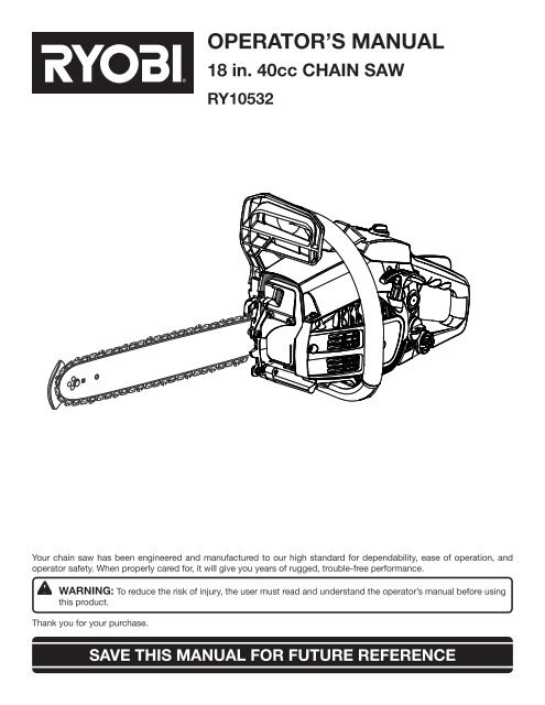
Your chain saw has been engineered and manufactured to our high standard for dependability, ease of operation, and<br />
operator safety. When properly cared for, it will give you years of rugged, trouble-free performance.<br />
WARNING: To reduce the risk of injury, the user must read and understand the operator’s manual before using<br />
this product.<br />
Thank you for your purchase.<br />
OPERATOR’S <strong>MANUAL</strong><br />
18 in. 40cc CHAIN SAW<br />
RY10532<br />
SAVE THIS <strong>MANUAL</strong> FOR FUTURE REFERENCE
TABLE OF CONTENTS<br />
Introduction ..................................................................................................................................................................... 2<br />
General Safety Rules ....................................................................................................................................................3-4<br />
Specific Safety Rules ....................................................................................................................................................... 4<br />
Symbols ........................................................................................................................................................................5-6<br />
Glossary of Terms ............................................................................................................................................................ 7<br />
<br />
Features ........................................................................................................................................................................8-9<br />
<br />
Assembly ......................................................................................................................................................................... 9<br />
Operation ..................................................................................................................................................................10-20<br />
Maintenance .............................................................................................................................................................21-32<br />
Bar and Chain Combinations ........................................................................................................................................ 33<br />
Troubleshooting ........................................................................................................................................................33-34<br />
Warranty ...................................................................................................................................................................35-37<br />
Parts Ordering / Service ...................................................................................................................................Back Page<br />
INTRODUCTION<br />
This product has many features for making its use more pleasant and enjoyable. Safety, performance, and dependability<br />
have been given top priority in the design of this product making it easy to maintain and operate.<br />
2
WARNING:<br />
Read and understand all instructions. Failure to follow<br />
all instructions listed below, may result in electric shock,<br />
fire and/or serious personal injury.<br />
READ ALL INSTRUCTIONS<br />
Know your tool. Read the operator’s manual carefully.<br />
Learn the saw’s applications and limitations as well as<br />
the specific potential hazards related to this tool.<br />
Kickback may occur when the nose or tip of the guide<br />
bar touches an object, or when the wood closes in and<br />
pinches the saw chain in the cut. Tip contact in some<br />
cases may cause a lightning-fast reverse reaction, kicking<br />
the guide bar up and back toward the operator. Pinching<br />
the saw chain along the top of the guide bar may push<br />
the guide bar rapidly back toward the operator. Either of<br />
these reactions may cause you to lose control of the saw,<br />
which could result in serious personal injury. Do not rely<br />
exclusively upon the safety devices built into the saw. As<br />
a chain saw user, you should take several steps to keep<br />
your cutting jobs free from accident or injury.<br />
• With a basic understanding of kickback, you can<br />
reduce or eliminate the element of surprise. Sudden<br />
surprise contributes to accidents.<br />
• Keep a good firm grip on the saw with both hands when<br />
the engine is running. Place your right hand on the rear<br />
handle and your left hand on the front handle with your<br />
thumbs and fingers encircling the chain saw handles.<br />
A firm grip together with a stiff left arm will help you<br />
maintain control of the saw if kickback occurs.<br />
• Make sure that the area in which you are cutting is<br />
free from obstructions. DO NOT let the nose of the<br />
guide bar contact a log, branch, fence, or any other<br />
obstruction that could be hit while you are operating<br />
the saw.<br />
• Cut at high engine speeds. Always cut with the engine<br />
running at full speed. Fully squeeze the throttle trigger<br />
and maintain a steady cutting speed.<br />
• Do not overreach or cut above chest height.<br />
• Follow the manufacturer’s sharpening and maintenance<br />
instructions for the saw chain.<br />
• Only use replacement bars and chains specified by<br />
the manufacturer or the equivalent.<br />
Do not operate a chain saw with one hand. Serious<br />
injury to the operator, helpers, bystanders, or any combination<br />
of these persons may result from one-handed<br />
operation. A chain saw is intended for two-handed use.<br />
Do not operate a chain saw when you are fatigued.<br />
Fatigue causes carelessness. Be more cautious before<br />
rest periods and towards the end of your shift. Never<br />
operate a chain saw when you are tired or under the<br />
influence of medication, drugs, or alcohol.<br />
Use safety footwear. Wear snug-fitting clothing,<br />
GENERAL SAFETY RULES<br />
3<br />
protective gloves, and eye, hearing, and head protection<br />
devices.<br />
Do not stand on any unstable surface while using the<br />
chain saw, such as ladders, scaffolds, trees, etc.<br />
Use caution when handling fuel. Move the chain saw<br />
at least 30 feet from the fueling point before starting the<br />
engine.<br />
Do not allow other persons to be near the chain saw<br />
when starting or cutting with the chain saw. Keep<br />
bystanders and animals out of the work area.<br />
Do not start cutting until you have a clear work area,<br />
secure footing, and a planned retreat path from the falling<br />
tree.<br />
Keep all parts of your body away from the saw chain<br />
when the engine is running.<br />
Always carry the chain saw with the engine stopped<br />
and the brake engaged, the guide bar and saw chain<br />
to the rear, and the muffler away from your body. When<br />
transporting the chain saw, use the appropriate guide bar<br />
scabbard.<br />
Do not operate a chain saw that is damaged, improperly<br />
adjusted, or not completely and securely assembled.<br />
Be sure that the saw chain stops moving when the throttle<br />
control trigger is released.<br />
Shut off the engine before setting the chain saw<br />
down. Do not leave the engine running unattended. As<br />
an additional safety precaution, apply the chain brake<br />
prior to setting down the saw.<br />
Use extreme caution when cutting small-size brush<br />
and saplings because slender material may catch the<br />
saw chain and be whipped toward you or pull you off<br />
balance.<br />
When cutting a limb that is under tension, be alert for<br />
springback so that you will not be struck when the tension<br />
in the wood fibers is released.<br />
Keep the handles dry, clean, and free of oil or fuel<br />
mixture.<br />
Beware of carbon monoxide poisoning. Operate the<br />
chain saw only in well-ventilated areas.<br />
Do not operate a chain saw in a tree unless you have<br />
been specifically trained to do so.<br />
Do not cut from a ladder; this is extremely dangerous.<br />
All chain saw service, other than the items listed in<br />
the instruction manual and all maintenance, should be<br />
performed by competent chain saw service personnel.<br />
(For example, if improper tools are used to remove the<br />
flywheel or if an improper tool is used to hold the flywheel<br />
in order to remove the clutch, structural damage to the<br />
flywheel could occur and subsequently could cause the<br />
flywheel to burst.)<br />
Always have a fire extinguisher available when using<br />
chain saw.<br />
Use only the replacement guide bars and low kickback<br />
chains specified for the saw.
Do not adapt the powerhead to a bow guide or use it<br />
to power any attachments or devices not listed for the<br />
saw.<br />
The gas powered saw (or electrically powered saw)<br />
is classified by CSA as a Class 1C (or Class 2C) saw.<br />
It is intended for infrequent use by homeowners, cottagers,<br />
and campers, and for such general applications as<br />
clearing, pruning, cutting firewood, etc. It is not intended<br />
WARNING:<br />
The warnings, labels, and instructions found in this section<br />
of the operator’s manual are for your safety. Failure<br />
to follow all instructions may result in serious personal<br />
injury.<br />
Do not cut vines and/or small underbrush (a diameter<br />
of less than 3 in.).<br />
Muffler surfaces are very hot during and after operation<br />
of the chain saw; keep all body parts away from<br />
the muffler. Serious burns may occur if contact is made<br />
with the muffler.<br />
Always hold the chain saw with both hands when<br />
the engine is running. Use a firm grip with thumbs and<br />
fingers encircling the chain saw handles.<br />
Never let anyone use the chain saw who has not<br />
received adequate instructions in its proper use. This<br />
applies to rentals as well as privately owned saws.<br />
Before you start the engine, make sure the saw chain<br />
is not contacting any object.<br />
Wear snug-fitting clothing. Always wear heavy long<br />
pants, boots, and gloves. Do not wear jewelry, short<br />
pants, sandals, or go barefoot. Do not wear loose fitting<br />
clothing, which could be drawn into the engine or catch<br />
the chain or underbrush. Wear overalls, jeans, or chaps<br />
made of cut-resistant material or ones that contain cutresistant<br />
inserts. Secure hair so that it is above shoulder<br />
level.<br />
Wear non-slip safety footwear and heavy-duty gloves<br />
to improve your grip and to protect your hands.<br />
Wear eye protection which is marked to comply with<br />
ANSI Z87.1, as well as hearing and head protection,<br />
when operating this equipment.<br />
Keep bystanders and animals out of the work area.<br />
Do not allow other persons to be nearby during starting<br />
or cutting with the chain saw.<br />
NOTE: The size of the work area depends on the job being<br />
performed as well as the size tree or workpiece involved.<br />
For example, felling a tree requires a larger work area than<br />
making other cuts (i.e., bucking cuts, etc.).<br />
GENERAL SAFETY RULES<br />
SPECIFIC SAFETY RULES<br />
4<br />
for prolonged use. Prolonged periods of operation can<br />
cause circulatory problems in the user’s hands due to<br />
vibration. For such use, it may be appropriate to use a<br />
saw having an anti-vibration feature.<br />
Save these instructions. Refer to them frequently and<br />
use to instruct other users. If you loan someone this tool,<br />
loan them these instructions also.<br />
Keep SAFE-T-TIP anti-kickback nose guard properly<br />
mounted on the guide bar to prevent rotational kickback.<br />
Follow the sharpening and maintenance instructions<br />
for the saw chain.<br />
Never operate a chain saw that is damaged, improperly<br />
adjusted, or is not completely and securely<br />
assembled. Be sure that the saw chain stops moving<br />
when the throttle control trigger is released. If the saw<br />
chain moves at idle speed, the carburetor may need<br />
adjusting. Refer to Adjusting the Carburetor in the<br />
Maintenance section of this manual. If the saw chain still<br />
moves at idle speed after adjustment has been made,<br />
contact an authorized service center for adjustment and<br />
discontinue use until the repair is made.<br />
REFUELING (DO NOT SMOKE!)<br />
To reduce the risk of fire and burn injury, handle fuel<br />
with care. It is highly flammable.<br />
Mix and store fuel in a container approved for gasoline.<br />
Mix fuel outdoors where there are no sparks or<br />
flames.<br />
Select bare ground, stop the engine, and allow it to<br />
cool before refueling.<br />
Loosen the fuel cap slowly to release pressure and to<br />
keep fuel from escaping around the cap.<br />
Tighten the fuel cap securely after refueling.<br />
Wipe spilled fuel from the unit. Move 30 feet away from<br />
refueling site before starting engine.<br />
Never attempt to burn off spilled fuel under any circumstances.<br />
KICKBACK<br />
Kickback is a dangerous reaction that can lead to<br />
serious injury. Do not rely only on the safety devices<br />
provided with the saw. As a chain saw user, you must<br />
take special safety precautions to help keep your cutting<br />
jobs free from accident or injury. See the General<br />
Safety Rules and Operation sections of this manual for<br />
added information on kickback and how to avoid serious<br />
personal injury.
SYMBOLS<br />
Some of the following symbols may be used on this tool. Please study them and learn their meaning. Proper interpretation<br />
of these symbols will allow you to operate the tool better and safer.<br />
SYMBOL NAME DESIGNATION/EXPLANATION<br />
Safety Alert Precautions that involve your safety.<br />
Read The Operator’s Manual<br />
Wear Eye, Hearing, and<br />
Head Protection<br />
SAFE-T-TIP Nose Guard<br />
To reduce the risk of injury, user must read and understand<br />
operator’s manual before using this product.<br />
Wear eye protection which is marked to comply with ANSI Z87.1<br />
as well as hearing and head protection when operating this<br />
equipment.<br />
The SAFE-T-TIP nose guard on the guide bar helps prevent<br />
kickback.<br />
No Smoking No smoking, sparks, or open flame.<br />
Operate With Two Hands Hold and operate the saw properly with both hands.<br />
One Handed Do not operate the saw using only one hand.<br />
Carbon Monoxide<br />
Kickback DANGER! Beware of kickback.<br />
Bar Nose Contact Avoid bar nose contact.<br />
Wear Gloves<br />
Gasoline and Oil<br />
Engines produce carbon monoxide which is an odorless, deadly<br />
poison. Do not operate in an enclosed area.<br />
Wear non-slip, heavy-duty protective gloves when handling the<br />
chain saw.<br />
Use unleaded gasoline intended for motor vehicle use with an<br />
octane rating of 87 [(R + M)/2] or higher. This product is powered<br />
by a 2-cycle engine and requires pre-mixing gasoline and 2-cycle<br />
oil.<br />
Keep Bystanders Away Keep all bystanders and animals at least 50 ft. away.<br />
5
SERVICE<br />
Servicing requires extreme care and knowledge and should<br />
be performed only by a qualified service technician. For<br />
service we suggest you return the product to your nearest<br />
AUTHORIZED SERVICE CENTER for repair. When servicing,<br />
use only identical replacement parts.<br />
WARNING:<br />
SYMBOLS<br />
The following signal words and meanings are intended to explain the levels of risk associated with this product.<br />
SYMBOL SIGNAL MEANING<br />
DANGER:<br />
WARNING:<br />
CAUTION<br />
CAUTION<br />
Indicates an imminently hazardous situation, which, if not avoided, will result<br />
in death or serious injury.<br />
Indicates a potentially hazardous situation, which, if not avoided, could result<br />
in death or serious injury.<br />
Indicates a potentially hazardous situation, which, if not avoided, may result in<br />
minor or moderate injury.<br />
(Without Safety Alert Symbol) Indicates a situation that may result in property<br />
damage.<br />
SAVE THESE INSTRUCTIONS<br />
6<br />
WARNING:<br />
To avoid serious personal injury, do not attempt to use<br />
this product until you read thoroughly and understand<br />
completely the operator’s manual. If you do not understand<br />
the warnings and instructions in the operator’s<br />
manual, do not use this product. Call <strong>Ryobi</strong> customer<br />
service for assistance.<br />
The operation of any power tool can result in foreign objects being thrown into your eyes, which can<br />
result in severe eye damage. Before beginning power tool operation, always wear safety goggles or<br />
safety glasses with side shields and, when needed, a full face shield. We recommend Wide Vision<br />
Safety Mask for use over eyeglasses or standard safety glasses with side shields. Always use eye<br />
protection which is marked to comply with ANSI Z87.1.
Bucking<br />
The process of cross cutting a felled tree or log into<br />
lengths.<br />
Chain Brake<br />
A device used to stop the saw chain.<br />
Chain Saw Powerhead<br />
A chain saw without the saw chain and guide bar.<br />
Clutch<br />
A mechanism for connecting and disconnecting a driven<br />
member to and from a rotating source of power.<br />
Drive Sprocket or Sprocket<br />
The toothed part that drives the saw chain.<br />
Felling<br />
The process of cutting down a tree.<br />
Felling Back Cut<br />
The final cut in a tree felling operation made on the opposite<br />
side of the tree from the notching undercut.<br />
Front Handle<br />
The support handle located at or toward the front of the<br />
chain saw. This handle is for the left hand.<br />
Front Handle Guard<br />
A structural barrier between the front handle of a chain<br />
saw and the guide bar, typically located close to the hand<br />
position on the front handle, and sometimes employed as<br />
an activating lever for a chain brake.<br />
Guide Bar<br />
A solid railed structure that supports and guides the saw<br />
chain.<br />
Kickback<br />
The backward or upward motion, or both, of the guide bar<br />
occurring when the saw chain near the nose of the top area<br />
of the guide bar contacts any object such as a log or branch,<br />
or when the wood closes in and pinches the saw chain in<br />
the cut.<br />
Kickback (Pinch)<br />
The rapid pushback of the saw which can occur when the<br />
wood closes in and pinches the moving saw chain in the cut<br />
along the top of the guide bar.<br />
GLOSSARY OF TERMS<br />
7<br />
Kickback (Rotational)<br />
The rapid upward and backward motion of the saw which<br />
can occur when the moving saw chain near the upper portion<br />
of the tip of the guide bar contacts an object, such as<br />
a log or branch.<br />
Low-Kickback Chain<br />
A chain that complies with the kickback performance<br />
requirements of ANSI B175.1 when tested on a representative<br />
sample of chain saws.<br />
Normal Cutting Position<br />
Those positions assumed in performing the bucking and<br />
felling cuts.<br />
Notching Undercut<br />
A notch cut in a tree that directs the tree’s fall.<br />
Rear Handle<br />
The support handle located at or toward the rear of the<br />
saw. It normally contains the throttle. This handle is for the<br />
right hand.<br />
Reduced Kickback Guide Bar<br />
A guide bar which has been demonstrated to reduce kickback<br />
significantly.<br />
Replacement Saw Chain<br />
A chain that complies with the kickback performance requirements<br />
of ANSI B175.1 when tested with specific chain saws.<br />
It may not meet the ANSI performance requirements when<br />
used with other saws.<br />
SAFE-T-TIP Anti-Kickback Nose Guard<br />
An attachment that may be provided on the end of the guide<br />
bar to prevent the chain at the end of the guide bar from<br />
contacting the wood.<br />
Saw Chain<br />
A loop of chain having cutting teeth that cut the wood, and<br />
that is driven by the motor and is supported by the guide<br />
bar.<br />
Springpole<br />
A small tree (sapling) or limb that is bent or trapped under<br />
tension. It may “spring back” rapidly when cut, causing a<br />
dangerous situation.
PRODUCT SPECIFICATIONS<br />
Bar length .......................................................................................................................................................................18 in.<br />
Chain pitch ................................................................................................................................................................. .375 in.<br />
Chain gauge ............................................................................................................................................................... .050 in.<br />
Chain type .................................................................................................................................... Low Profile Full Skip Tooth<br />
Chain drive links .................................................................................................................................................................. 62<br />
Drive sprocket .............................................................................................................................................................6-tooth<br />
Engine displacement .................................................................................................................................. 2.45 cu. in. (40cc)<br />
Idle engine speed ............................................................................................................................2,700 ± 200 r/min. (RPM)<br />
Fuel tank capacity ......................................................................................................................................................10.4 oz.<br />
Chain oil tank capacity .................................................................................................................................................7.1 oz.<br />
Weight - No bar, chain, fuel or oil ................................................................................................................................ 9.5 lbs.<br />
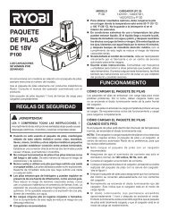
CYLINDER<br />
COVER<br />
PRIMER<br />
BULB<br />
FRONT<br />
HANDLE<br />
CHAIN BRAKE /<br />
FRONT HAND<br />
GUARD<br />
LOW KICKBACK<br />
SAW CHAIN<br />
CHOKE KNOB<br />
FEATURES<br />
STARTER/FAN<br />
HOUSING<br />
GUIDE BAR<br />
CLUTCH COVER<br />
8<br />
BAR<br />
MOUNTING<br />
NUTS<br />
FUEL CAP<br />
STARTER<br />
GRIP<br />
CHAIN OIL<br />
CAP<br />
SAFE-T-TIP<br />
ANTI-KICKBACK<br />
NOSE GUARD<br />
IGNITION<br />
SWITCH<br />
THROTTLE<br />
TRIGGER<br />
TRIGGER<br />
RELEASE<br />
REAR<br />
HANDLE<br />
Fig. 1
KNOW YOUR CHAIN SAW<br />
See Figure 1.<br />
The safe use of this product requires an understanding of<br />
the information on the tool and in this operator’s manual as<br />
well as a knowledge of the project you are attempting. Before<br />
use of this product, familiarize yourself with all operating<br />
features and safety rules.<br />
CHOKE KNOB<br />
The choke knob opens and closes the choke valve in the<br />
carburetor. Positions available include FULL CHOKE, HALF<br />
CHOKE, and RUN.<br />
COMBINATION WRENCH<br />
A combination wrench tool is provided for use when performing<br />
various maintenance procedures. On-board storage<br />
keeps the tool handy at all times.<br />
CHAIN BRAKE / FRONT HAND GUARD<br />
The chain brake is designed to quickly stop the chain from<br />
rotating. When the chain brake / front hand guard is pushed<br />
toward the bar, the chain should stop immediately. The chain<br />
brake does not prevent kickback.<br />
UNPACKING<br />
This product has been shipped completely assembled.<br />
Carefully remove the tool and any accessories from the<br />
box. Make sure that all items listed in the packing list are<br />
included.<br />
Inspect the tool carefully to make sure no breakage or<br />
damage occurred during shipping.<br />
Do not discard the packing material until you have carefully<br />
inspected and satisfactorily operated the tool.<br />
If any parts are damaged or missing, please call<br />
1-800-860-4050 for assistance.<br />
PACKING LIST<br />
Chain Saw<br />
Scabbard<br />
Combination Wrench<br />
2-Cycle Engine Oil<br />
Operator’s Manual<br />
Case<br />
FEATURES<br />
ASSEMBLY<br />
9<br />
GUIDE BAR<br />
The factory-equipped guide bar has a small radius tip that<br />
offers a somewhat lower kickback potential.<br />
LOW KICKBACK SAW CHAIN<br />
The low kickback saw chain helps minimize the force of a<br />
kickback reaction by preventing the cutters from digging in<br />
too deeply at the kickback zone.<br />
PRIMER BULB<br />
The primer bulb pumps fuel from the fuel tank to the<br />
carburetor.<br />
SAFE-T-TIP ANTI-KICKBACK NOSE GUARD<br />
The SAFE-T-TIP Anti-Kickback Nose Guard is an attachment<br />
provided on the end of the guide bar to prevent the<br />
chain on the end of the guide bar from contacting the<br />
wood.<br />
THROTTLE TRIGGER<br />
The throttle trigger is used for starting the chain saw, and<br />
also for controlling chain rotation.<br />
WARNING:<br />
If any parts are damaged or missing do not operate this<br />
tool until the parts are replaced. Failure to heed this<br />
warning could result in serious personal injury.<br />
WARNING:<br />
Do not attempt to modify this tool or create accessories<br />
not recommended for use with this tool. Any such<br />
alteration or modification is misuse and could result in a<br />
hazardous condition leading to possible serious personal<br />
injury.<br />
NOTE: The chain saw has been fully factory tested. It is<br />
normal to find some slight oil residue on the saw. Read<br />
and remove all hang tags and store with the Operator’s<br />
Manual.
WARNING:<br />
Do not allow familiarity with tools to make you careless.<br />
Remember that a careless fraction of a second is<br />
sufficient to inflict serious injury.<br />
WARNING:<br />
Always wear safety goggles or safety glasses with<br />
side shields when operating this tool. Failure to do so<br />
could result in objects being thrown into your eyes<br />
resulting in possible serious injury.<br />
WARNING:<br />
Do not use any attachments or accessories not recommended<br />
by the manufacturer of this tool. The use of<br />
attachments or accessories not recommended can result<br />
in serious personal injury.<br />
APPLICATIONS<br />
You may use this tool for the purposes listed below:<br />
Basic limbing, felling, and woodcutting<br />
Removing buttress roots<br />
WARNING:<br />
Always shut off engine before fueling. Never add fuel to<br />
a machine with a running or hot engine. Move at least<br />
30 ft. from refueling site before starting the engine. DO<br />
NOT SMOKE! Failure to heed this warning can result in<br />
possible personal injury.<br />
OPERATION<br />
10<br />
FUEL AND REFUELING<br />
HANDLING THE FUEL SAFELY<br />
WARNING:<br />
Check for fuel leaks. If any are found, correct them before<br />
using the saw to prevent fire or burn injury.<br />
Always handle fuel with care; it is highly flammable.<br />
Always refuel outdoors and do not inhale fuel vapors.<br />
Do not let gasoline or oil come in contact with skin.<br />
Keep gasoline and oil away from the eyes. If gasoline or oil<br />
comes in contact with the eyes, wash them immediately<br />
with clean water. If irritation is still present, see a doctor<br />
immediately.<br />
Clean up spilled fuel immediately.<br />
Refer to Refueling in the Specific Safety Rules section of<br />
this manual for additional safety information.<br />
MIXING THE FUEL<br />
This product is powered by a 2-cycle engine and requires<br />
pre-mixing gasoline and 2-cycle oil. Pre-mix unleaded<br />
gasoline and 2-cycle engine oil in a clean container<br />
approved for gasoline.<br />
This engine is certified to operate on unleaded gasoline<br />
intended for automotive use with an octane rating of 87<br />
[(R + M) / 2] or higher.<br />
Do not use any type of pre-mixed gasoline/oil from fuel<br />
service stations, this includes the pre-mixed gasoline/oil<br />
intended for use in mopeds, motorcycles, etc.<br />
Use a high quality 2-cycle self-mixing oil for air-cooled<br />
engines. Do not use automotive oil or 2-cycle outboard<br />
oil.<br />
Mix 2% oil into the gasoline. This is a 50:1 ratio.<br />
Mix the fuel thoroughly and each time before fueling.<br />
Mix in small quantities. Do not mix quantities larger than<br />
usable in a 30-day period. A 2-cycle oil containing a fuel<br />
stabilizer is recommended.<br />
PREMIUM EXACT MIX (50:1)<br />
GASOLINE OIL<br />
1 Gallon (US) 2.6 oz.<br />
1 Liter 20 cc (20 ml)
FILLING THE FUEL TANK<br />
See Figure 2.<br />
Clean the surface around the fuel cap to prevent contamination.<br />
Loosen the fuel cap slowly.<br />
Carefully pour the fuel mixture into the tank. Avoid spillage.<br />
Prior to replacing the fuel cap, clean and inspect the<br />
o-ring.<br />
Immediately replace the fuel cap and hand tighten. Wipe<br />
up any fuel spillage.<br />
NOTE: It is normal for the engine to emit smoke during and<br />
after the first use.<br />
ADDING BAR AND CHAIN OIL<br />
See Figure 3.<br />
Use a bar and chain oil designed for lubricating chain saw<br />
chains. They are formulated to extend bar and chain life<br />
by protecting against wear and reducing friction and heat.<br />
Chain saw should use approximately one tank of oil per<br />
tank of fuel.<br />
NOTE: Do not use dirty, used, or otherwise contaminated<br />
oils. Damage may occur to the oil pump, bar, or chain.<br />
Carefully pour the bar and chain oil into the oil tank.<br />
Fill the oil tank every time you fuel the engine.<br />
OPERATING THE CHAIN BRAKE<br />
See Figures 4 - 5.<br />
Check the operating condition of the chain brake prior to<br />
each use.<br />
Using the back of your left hand, engage the chain brake<br />
by pushing the chain brake lever/hand guard toward the<br />
bar while the chain is rotating rapidly.<br />
Reset the chain brake back into the RUN position by<br />
grasping the top of the chain brake lever/hand guard and<br />
pulling toward the front handle until you hear a click.<br />
WARNING:<br />
If the chain brake does not stop the chain immediately, or<br />
if the chain brake will not stay in the run position without<br />
assistance, take the saw to an authorized service center<br />
for repair prior to use.<br />
OPERATION<br />
11<br />
Fig. 2<br />
Fig. 3<br />
BRAKE<br />
POSITION<br />
Fig. 4<br />
RUN<br />
POSITION<br />
Fig. 5
STARTING THE ENGINE<br />
See Figures 6 - 10.<br />
The starting method differs depending on whether the engine<br />
is cold or warm.<br />
WARNING:<br />
Keep your body to the left of the chain line. Never straddle<br />
the saw or chain, or lean over past the chain line.<br />
Place the chain saw on level ground and ensure that no<br />
objects or obstructions are in the immediate vicinity that<br />
could come in contact with the bar and chain. To prevent<br />
rapid dulling of the chain, do not allow the bar and chain<br />
to contact dirt on the ground.<br />
Hold the front handle firmly with your left hand and put<br />
your right foot onto the base of the rear handle.<br />
To Start a Cold Engine:<br />
Set the ignition switch to the RUN ( I ) position.<br />
Make sure the chain brake is in the run position by pulling<br />
back on the lever/hand guard.<br />
Fully press and release the primer bulb 7 times.<br />
Pull choke knob all the way out to FULL CHOKE ( )<br />
position.<br />
Pull the starter grip until the engine attempts to start, but<br />
no more than 5 times.<br />
Push choke knob to HALF CHOKE ( ) position.<br />
Pull starter grip until engine runs.<br />
NOTE: Allow the saw to run in this position 15-30<br />
seconds, depending upon the temperature.<br />
Push the choke knob in to the RUN ( ) position.<br />
IGNITION SWITCH<br />
IN THE RUN<br />
POSITION<br />
OPERATION<br />
Fig. 6<br />
12<br />
RUN<br />
PRIMER BULB<br />
HALF<br />
CHOKE<br />
FULL<br />
CHOKE<br />
FULL CHOKE<br />
POSITION<br />
RUN POSITION<br />
STARTER<br />
GRIP<br />
Fig. 7<br />
Fig. 8<br />
Fig. 9<br />
Fig. 10
CAUTION:<br />
Failure to release partial throttle when chain brake lever<br />
is in the brake position will result in serious damage to<br />
the unit. Never squeeze and hold the throttle trigger while<br />
the chain brake is in the brake position.<br />
To Start a Warm Engine:<br />
Set the ignition switch to the RUN ( I ) position.<br />
Make sure the chain brake is in the run position by pulling<br />
back on the lever/hand guard.<br />
Fully press and release the primer bulb 7 times.<br />
Pull starter grip until engine runs.<br />
STOPPING THE ENGINE<br />
See Figures 11 - 12.<br />
Release the throttle trigger and let the engine return to<br />
idle. To stop the engine, move the ignition switch to the<br />
STOP ( ) position. Do not put the chain saw on the ground<br />
when the chain is still moving. For additional safety, set the<br />
chain brake when the saw is not in use.<br />
In the event that the ignition switch will not stop the saw,<br />
pull the choke knob out to the fully extended position (FULL<br />
CHOKE / ) and engage chain brake to stop the engine.<br />
If the ignition switch will not stop the saw when set to the<br />
STOP position, have the ignition switch repaired before<br />
using the chain saw again to prevent unsafe conditions or<br />
serious injury.<br />
NOTE: When you are finished using the saw, always relieve<br />
tank pressure by loosening, then retightening, the chain oil<br />
and fuel mix caps. Allow the engine to cool before storing.<br />
OPERATION<br />
13<br />
IGNITION SWITCH<br />
IN THE STOP<br />
POSITION<br />
Fig. 11<br />
BRAKE POSITION<br />
Fig. 12
ADJUSTING IDLE SPEED<br />
See Figure 13.<br />
If the engine starts, runs, and accelerates, but will not<br />
idle, turn the idle speed screw “T” clockwise to increase<br />
idle speed.<br />
If the chain turns at idle, turn the idle speed screw “T”<br />
counterclockwise to reduce the idle RPM and stop the<br />
chain movement. If the saw chain still moves at idle speed,<br />
contact an authorized service center for adjustment and<br />
discontinue use until the repair is made.<br />
WARNING:<br />
THE SAW CHAIN SHOULD NEVER TURN AT IDLE. Turn<br />
the idle speed screw “T” counterclockwise to reduce the<br />
idle RPM and stop the chain, or contact an authorized<br />
service center for adjustment and discontinue use until<br />
the repair is made. Serious personal injury may result<br />
from the saw chain turning at idle.<br />
PULL AND PUSH<br />
See Figure 14.<br />
The reaction force of the saw is always opposite to the direction<br />
the chain is moving. Thus, the operator must be ready<br />
to control the PULL when cutting on the bottom edge of the<br />
bar and the PUSH when cutting along the top edge.<br />
NOTE: The chain saw has been fully factory tested. It is<br />
normal to find some slight oil residue on the saw.<br />
WARNING:<br />
KICKBACK occurs when the moving chain contacts an<br />
object at the upper portion of the tip of the guide bar or<br />
when the wood closes in and pinches the saw chain in the<br />
cut. Contact at the upper portion of the tip of the guide<br />
bar can cause the chain to dig into the object and stop the<br />
chain for an instant. The result is a lightning-fast reverse<br />
reaction which kicks the guide bar up and back toward<br />
the operator. If the saw chain is pinched along the top of<br />
the guide bar, the guide bar can be driven rapidly back<br />
toward the operator. Either of these reactions can cause<br />
loss of saw control, which can result in serious injury.<br />
Do not rely exclusively upon the safety devices built<br />
into the saw. As a chain saw user, you should take<br />
steps to keep your cutting jobs free from accident or<br />
injury. See General Safety Rules for more details.<br />
OPERATION<br />
14<br />
PULL<br />
PUSH<br />
IDLE SPEED<br />
SCREW “T”<br />
Fig. 13<br />
Fig. 14
KICKBACK PRECAUTIONS<br />
See Figures 15 - 16.<br />
Rotational kickback occurs when the moving chain contacts<br />
an object at the Kickback Danger Zone of the guide bar. The<br />
result is a lightning-fast reverse reaction, which kicks the<br />
guide bar up and back towards the operator. This reaction can<br />
cause loss of control, which can result in serious injury.<br />
PREPARING FOR CUTTING<br />
PROPER GRIP ON HANDLES<br />
See Figure 17.<br />
See General Safety Rules for appropriate safety equipment.<br />
Wear non-slip gloves for maximum grip and protection.<br />
Hold the saw firmly with both hands. Always keep your<br />
left hand on the front handle and your right hand on the<br />
rear handle so that your body is to the left of the chain<br />
line.<br />
WARNING:<br />
Never use a left-handed (cross-handed) grip or any<br />
stance that would place your body or arm across the<br />
chain line.<br />
Maintain a proper grip on the saw whenever the engine<br />
is running. The fingers should encircle the handle and the<br />
thumb is wrapped under the handlebar. This grip is least<br />
likely to be broken by a kickback or other sudden reaction<br />
of the saw. Any grip in which the thumb and fingers are<br />
on the same side of the handle is dangerous because a<br />
slight kick of the saw can cause loss of control.<br />
WARNING:<br />
CHAIN LINE<br />
DO NOT operate the throttle trigger with your left hand<br />
and hold the front handle with your right hand. Never<br />
allow any part of your body to be in the chain line while<br />
operating a saw.<br />
OPERATION<br />
15<br />
PROPER GRIP<br />
KICKBACK<br />
DANGER ZONE<br />
ROTATIONAL<br />
KICKBACK<br />
PROPER HAND<br />
GRIP POSITION<br />
IMPROPER GRIP<br />
Fig. 15<br />
Fig. 16<br />
Fig. 17
PROPER CUTTING STANCE<br />
See Figure 18.<br />
Balance your weight with both feet on solid ground.<br />
Keep left arm with elbow locked in a “straight arm” position<br />
to withstand any kickback force.<br />
Keep your body to the left of the chain line.<br />
Keep your thumb on underside of handlebar.<br />
WORK AREA PRECAUTIONS<br />
See Figure 19.<br />
Cut only wood or materials made from wood; no sheet<br />
metal, no plastics, no masonry, no non-wood building<br />
materials.<br />
Never allow children to operate the saw. Allow no person<br />
to use this chain saw who has not read this operator’s<br />
manual or received adequate instructions for the safe and<br />
proper use of this chain saw.<br />
Keep everyone – helpers, bystanders, children, and animals,<br />
a SAFE DISTANCE from the cutting area. During<br />
felling operations, the safe distance should be a least<br />
twice the height of the largest trees in the felling area.<br />
During bucking operations, keep a minimum distance of<br />
15 feet between workers.<br />
Always cut with both feet on solid ground to prevent being<br />
pulled off balance.<br />
Do not cut above chest height as a saw held higher is<br />
difficult to control against kickback forces.<br />
Do not fell trees near electrical wires or buildings. Leave<br />
this operation for professionals.<br />
Cut only when visibility and light are adequate for you to<br />
see clearly.<br />
BASIC OPERATING/CUTTING PROCEDURES<br />
Practice cutting a few small logs using the following technique<br />
to get the “feel” of using the saw before you begin a major<br />
sawing operation.<br />
Take the proper stance in front of the wood with the saw<br />
idling.<br />
Accelerate the engine to full throttle just before entering<br />
the cut by squeezing the throttle trigger.<br />
OPERATION<br />
16<br />
THUMB ON<br />
UNDERSIDE OF<br />
HANDLE BAR<br />
CHAIN LINE<br />
STRAIGHT<br />
ARM<br />
Fig. 18<br />
Fig. 19<br />
Begin cutting with the saw against the log.<br />
Keep the engine at full throttle the entire time you are<br />
cutting.<br />
Allow the chain to cut for you; exert only light downward<br />
pressure. Forcing the cut could result in damage to the<br />
bar, chain, or engine.<br />
Release the throttle trigger as soon as the cut is completed<br />
allowing the engine to idle. Running the saw at full<br />
throttle without a cutting load can result in unnecessary<br />
wear to the chain, bar, and engine.<br />
Do not put pressure on the saw at the end of the cut.
FELLING TREES<br />
HAZARDOUS CONDITIONS<br />
WARNING:<br />
Do not fell trees during periods of high wind or heavy<br />
precipitation. Wait until the hazardous weather has<br />
ended.<br />
When felling a tree, it is important that you heed the following<br />
warnings to prevent possible serious injury.<br />
Do not cut down trees having an extreme lean or large<br />
trees with rotten limbs, loose bark, or hollow trunks. Have<br />
these trees pushed or dragged down with heavy equipment,<br />
then cut them up.<br />
Do not cut trees near electrical wires or buildings.<br />
Check the tree for damaged or dead branches that could<br />
fall and hit you during felling.<br />
Periodically glance at the top of the tree during the<br />
backcut to assure the tree is going to fall in the desired<br />
direction.<br />
If the tree starts to fall in the wrong direction, or if the saw<br />
gets caught or hung up during the fall, leave the saw and<br />
save yourself!<br />
PROPER PROCEDURE FOR TREE FELLING<br />
See Figures 20 - 23.<br />
Pick your escape route (or routes, in case the intended<br />
route is blocked). Clear the immediate area around the<br />
tree and make sure there are no obstructions in your<br />
planned path of retreat. Clear the path of safe retreat<br />
approximately 135° from the planned line of fall.<br />
Consider the force and direction of the wind, the lean<br />
and balance of the tree, and the location of large limbs.<br />
These things influence the direction in which the tree will<br />
fall. Do not try to fell a tree along a line different from its<br />
natural line of fall.<br />
Cut a notch about 1/3 the diameter of the trunk in the<br />
side of the tree. Make the notch cuts so they intersect<br />
at a right angle to the line of fall. This notch should be<br />
cleaned out to leave a straight line. To keep the weight<br />
of the wood off the saw, always make the lower cut of<br />
the notch before the upper cut.<br />
Make the backcut level and horizontal, and at a minimum<br />
of 2 in. above the horizontal cut of the notch.<br />
NOTE: Never cut through to the notch. Always leave a<br />
band of wood between the notch and back cut (approximately<br />
2 in. or 1/10 the diameter of the tree). This is called<br />
“hinge” or “hingewood.” It controls the fall of the tree and<br />
prevents slipping or twisting or shootback of the tree off<br />
the stump.<br />
OPERATION<br />
17<br />
PLANNED LINE OF<br />
FALL<br />
135° FROM<br />
PLANNED LINE<br />
OF FALL<br />
PLANNED<br />
LINE OF FALL<br />
BACK CUT<br />
2 in. (51 mm)<br />
135°<br />
135°<br />
45°<br />
45°<br />
HINGE<br />
2 in. (51 mm) OR 1/10 DIA<br />
90°<br />
90°<br />
PATH OF<br />
SAFE RETREAT<br />
PATH<br />
OF SAFE<br />
RETREAT<br />
Fig. 20<br />
NOTCH -<br />
APPROX. 1/3<br />
DIAMETER OF<br />
TRUNK<br />
Fig. 21
On large diameter trees, stop the back cut before it is<br />
deep enough for the tree to either fall or settle back on<br />
the stump. Then insert soft wooden or plastic wedges into<br />
the cut so they do not touch the chain. Drive wedges in,<br />
little by little, to help jack the tree over.<br />
When bucking or felling with a wedge, it may be necessary<br />
to remove the SAFE-T-TIP anti-kickback device to allow<br />
the bar to be drawn through the cut. After you complete<br />
the cut, reinstall the tip immediately.<br />
As tree starts to fall, stop the chain saw and put it down<br />
immediately. Retreat along the cleared path, but watch<br />
the action in case something falls your way.<br />
WARNING:<br />
Never cut through to the notch when making a back cut.<br />
The hinge controls the fall of the tree, this is the section<br />
of wood between the notch and backcut.<br />
REMOVING BUTTRESS ROOTS<br />
See Figure 24.<br />
A buttress root is a large root extending from the trunk of the<br />
tree above the ground. Remove large buttress roots prior to<br />
felling. Make the horizontal cut into the buttress first, followed<br />
by the vertical cut. Remove the resulting loose section from<br />
the work area. Follow the correct tree felling procedure as<br />
stated in Proper Procedure For Tree Felling after you have<br />
removed the large buttress roots.<br />
BUCKING<br />
See Figure 25.<br />
Bucking is the term used for cutting a fallen tree to the<br />
desired log length.<br />
Cut only one log at a time.<br />
Support small logs on a saw horse or another log while<br />
bucking.<br />
Keep a clear cutting area. Make sure that no objects<br />
can contact the guide bar nose and chain during cutting,<br />
this can cause kickback. To avoid the danger, keep the<br />
SAFE-T-TIP anti-kickback device attached while cutting.<br />
Refer to Kickback in the Specific Safety Rules section of<br />
this manual for more information.<br />
During bucking operations, stand on the uphill side so<br />
that the cut-off section of the log cannot roll over you.<br />
Sometimes it is impossible to avoid pinching (with just<br />
standard cutting techniques) or difficult to predict which<br />
way a log will settle when cut.<br />
OPERATION<br />
18<br />
BACK CUT<br />
WEDGE Fig. 23<br />
KICKBACK<br />
VERTICAL<br />
CUT<br />
HINGE<br />
LOOSE<br />
SECTION<br />
Fig. 22<br />
HORIZONTAL<br />
CUT<br />
Fig. 24<br />
Fig. 25
BUCKING WITH A WEDGE<br />
See Figure 26.<br />
If the wood diameter is large enough for you to insert a soft<br />
bucking wedge without touching the chain, you should use<br />
the wedge to hold the cut open to prevent pinching.<br />
NOTE: When bucking or felling with a wedge, you may need<br />
to remove the SAFE-T-TIP anti-kickback device to allow the<br />
bar to be drawn through the cut. After you complete the cut,<br />
reinstall the tip.<br />
BUCKING LOGS UNDER STRESS<br />
See Figure 27.<br />
Make the first bucking cut 1/3 of the way through the log<br />
and finish with a 2/3 cut on the opposite side. As you cut<br />
the log, it will tend to bend. The saw can become pinched<br />
or hung in the log if you make the first cut deeper than 1/3<br />
of the diameter of the log.<br />
Give special attention to logs under stress to prevent the<br />
bar and chain from pinching.<br />
OVERBUCKING<br />
See Figure 28.<br />
Begin on the top side of the log with the bottom of the saw<br />
against the log; exert light pressure downward. Note that<br />
the saw will tend to pull away from you.<br />
OPERATION<br />
19<br />
FINISHING CUT<br />
LOAD<br />
WEDGE<br />
LOG SUPPORTED AT ONE END<br />
1ST CUT 1/3 DIA.<br />
LOG SUPPORTED AT BOTH ENDS<br />
1ST CUT 1/3 DIA.<br />
FINISHING CUT<br />
LOAD<br />
Fig. 26<br />
Fig. 27<br />
OVERBUCKING Fig. 28
UNDERBUCKING<br />
See Figure 29.<br />
Begin on the underside of the log with the top of the saw<br />
against the log; exert light pressure upward. During underbucking,<br />
the saw will tend to push back at you. Be prepared for<br />
this reaction and hold the saw firmly to maintain control.<br />
LIMBING AND PRUNING<br />
See Figures 30 - 31.<br />
Work slowly, keeping both hands on the saw with a firm<br />
grip. Maintain secure footing and balance.<br />
Keep the tree between you and the chain while limbing.<br />
Do not cut from a ladder. This is extremely dangerous.<br />
Leave this operation for professionals.<br />
Do not cut above chest height. A saw held higher than<br />
chest height is difficult to control against kickback.<br />
WARNING:<br />
Never climb into a tree to limb or prune. Do not stand on<br />
ladders, platforms, a log, or in any position which can<br />
cause you to lose your balance or control of the saw.<br />
When pruning trees it is important not to make the flush<br />
cut next to the main limb or trunk until you have cut off<br />
the limb further out to reduce the weight. This prevents<br />
stripping the bark from the main member.<br />
• Underbuck the branch 1/3 through for your first cut.<br />
• Overbuck the branch to drop it.<br />
• Finish by cutting smoothly and neatly against the<br />
main member so the bark will grow back to seal the<br />
wound.<br />
WARNING:<br />
If the limbs to be pruned are above chest height, hire a<br />
professional to perform the pruning.<br />
CUTTING SPRINGPOLES<br />
See Figure 32.<br />
A springpole is any log, branch, rooted stump, or sapling<br />
which is bent under tension by other wood so that it springs<br />
back if the wood holding it is cut or removed. On a fallen<br />
tree, a rooted stump has a high potential of springing back<br />
to the upright position during the bucking cut to separate<br />
the log from the stump. Watch out for springpoles — they<br />
are dangerous.<br />
WARNING:<br />
Springpoles are dangerous and could strike the operator,<br />
causing the operator to lose control of the chain saw. This<br />
could result in severe or fatal injury to the operator.<br />
OPERATION<br />
20<br />
LOAD<br />
FIRST CUT<br />
1/3 DIA.<br />
FINISHING CUT<br />
UNDERBUCKING Fig. 29<br />
SECOND CUT<br />
SPRINGPOLE<br />
Fig. 30<br />
CUT LIMBS ONE AT A TIME AND LEAVE SUPPORT LIMBS<br />
UNDER TREE UNTIL LOG IS CUT<br />
Fig. 31<br />
Fig. 32
WARNING:<br />
When servicing, use only identical replacement parts.<br />
Use of any other parts may create a hazard or cause<br />
product damage.<br />
WARNING:<br />
Always wear safety goggles or safety glasses with side<br />
shields during power tool operation or when blowing<br />
dust. If operation is dusty, also wear a dust mask.<br />
GENERAL MAINTENANCE<br />
Avoid using solvents when cleaning plastic parts. Most<br />
plastics are susceptible to damage from various types of<br />
commercial solvents and may be damaged by their use. Use<br />
clean cloths to remove dirt, dust, oil, grease, etc.<br />
WARNING:<br />
Do not at any time let brake fluids, gasoline, petroleumbased<br />
products, penetrating oils, etc., come in contact<br />
with plastic parts. Chemicals can damage, weaken or<br />
destroy plastic which may result in serious personal<br />
injury.<br />
LUBRICATION<br />
All of the bearings in this tool are lubricated with a sufficient<br />
amount of high grade lubricant for the life of the unit under<br />
normal operating conditions. Therefore, no further lubrication<br />
is required.<br />
REPLACING THE GUIDE BAR AND CHAIN<br />
See Figures 33 - 42.<br />
DANGER:<br />
Never start the engine before installing the guide bar,<br />
chain, drivecase cover, and clutch drum. Without all these<br />
parts in place, the clutch can fly off or explode, exposing<br />
the user to possible serious injury.<br />
WARNING:<br />
To avoid serious personal injury, read and understand all<br />
the safety instructions in this section.<br />
Always place the switch in the STOP “ ” position before<br />
you work on the saw.<br />
Make sure the chain brake is not set by pulling the chain<br />
brake lever/hand guard towards the front handle to the<br />
run position.<br />
MAINTENANCE<br />
21<br />
BAR MOUNTING NUTS<br />
SPROCKET<br />
CLUTCH<br />
COVER<br />
GUIDE<br />
BAR<br />
RUN POSITION<br />
Fig. 33<br />
COMBINATION<br />
WRENCH<br />
Fig. 34<br />
BAR<br />
MOUNTING<br />
NUTS<br />
Fig. 35<br />
NOTE: When replacing the guide bar and chain, always<br />
use the specified bar and chain listed in the Bar and Chain<br />
Combinations section later in this manual.<br />
Wear gloves when handling the chain and bar. These<br />
components are sharp and may contain burrs.<br />
Remove the bar mounting nuts using the combination<br />
wrench provided.<br />
Remove the clutch cover.<br />
Remove the bar and chain from the mounting surface.<br />
Remove the old chain from the bar.<br />
TOP
Lay out the new saw chain in a loop and straighten any<br />
kinks. The cutters should face in the direction of chain<br />
rotation. If they face backwards, turn the loop over.<br />
Place the chain drive links into the bar groove as<br />
shown.<br />
Position the chain so there is a loop at the back of the<br />
bar.<br />
Hold the chain in position on the bar and place the loop<br />
around the sprocket.<br />
CUTTERS CHAIN ROTATION<br />
CHAIN DRIVE LINKS<br />
CHAIN DRIVE LINKS<br />
MAINTENANCE<br />
Fig. 36<br />
BAR<br />
GROOVE<br />
Fig. 37<br />
22<br />
SPROCKET<br />
TOP<br />
PIN<br />
HOLE<br />
SPROCKET<br />
CHAIN TENSIONING<br />
SCREW<br />
BAR<br />
MOUNTING<br />
NUTS<br />
CLUTCH<br />
COVER<br />
CHAIN TENSION<br />
ADJUSTING PIN<br />
Fig. 38<br />
Fig. 39
Fit the bar flush against the mounting surface so that the<br />
bar studs are in the long slot of the bar.<br />
NOTE: When placing the bar on the bar studs, ensure<br />
that the adjusting pin is in the chain tension pin hole.<br />
Replace the clutch cover and bar mounting nuts.<br />
Finger-tighten the bar mounting nuts. The bar must be<br />
free to move for tension adjustment.<br />
Remove all slack from the chain by turning the chain<br />
tensioning screw clockwise until the chain seats snugly<br />
against the bar with the drive links in the bar groove.<br />
Lift the tip of the guide bar up to check for sag.<br />
Release the tip of the guide bar and turn the chain tensioning<br />
screw 1/2 turn clockwise. Repeat this process until<br />
sag does not exist.<br />
Hold the tip of the guide bar up and tighten the bar mounting<br />
nuts securely.<br />
The chain is correctly tensioned when there is no sag on<br />
the underside of the guide bar, the chain is snug, but it can<br />
be turned by hand without binding. Ensure that the chain<br />
brake is not set.<br />
NOTE: If chain is too tight, it will not rotate. Loosen the bar<br />
nuts slightly and turn the tension adjuster 1/4 turn counterclockwise.<br />
Lift the tip of the guide bar up and retighten the<br />
bar nuts securely. Ensure that the chain will rotate without<br />
binding.<br />
ADJUSTING THE CHAIN TENSION<br />
See Figures 43 - 45.<br />
WARNING:<br />
Never touch or adjust the chain while the motor is running.<br />
The saw chain is very sharp. Always wear protective<br />
gloves when performing maintenance on the chain.<br />
Stop the engine before setting the chain tension.<br />
Make sure the bar mounting nuts are loosened to finger<br />
tight.<br />
Turn the chain tensioning screw clockwise to tension the<br />
chain.<br />
NOTE: A cold chain is correctly tensioned when there is<br />
no slack on the underside of the guide bar, the chain is<br />
snug, and it can be turned by hand without binding.<br />
MAINTENANCE<br />
23<br />
FLATS ON DRIVE LINKS<br />
Fig. 40<br />
Fig. 41<br />
Fig. 42<br />
Fig. 43
Retension the chain whenever the flats on the drive links<br />
hang out of the bar groove.<br />
NOTE: During normal saw operation, the temperature<br />
of the chain increases. The drive links of a correctly tensioned<br />
warm chain will hang approximately .050 in. out<br />
of the bar groove. The tip of the combination wrench can<br />
be used as a guide to help determine the correct warm<br />
chain tension.<br />
NOTE: New chains tend to stretch; check the chain tension<br />
frequently and tension as required.<br />
CAUTION:<br />
A chain tensioned while warm may be too tight upon<br />
cooling. Check the “cold tension” before next use.<br />
CHAIN MAINTENANCE<br />
See Figures 46 - 47.<br />
CAUTION:<br />
Check that the switch is in the STOP “ ” position before<br />
you work on the saw.<br />
Use only a low-kickback chain on this saw. This fastcutting<br />
chain provides kickback reduction when properly<br />
maintained.<br />
For smooth and fast cutting, maintain the chain properly.<br />
The chain requires sharpening when the wood chips are<br />
small and powdery, the chain must be forced through the<br />
wood during cutting, or the chain cuts to one side. During<br />
maintenance of the chain, consider the following:<br />
Improper filing angle of the side plate can increase the<br />
risk of severe kickback.<br />
Raker (depth gauge) clearance.<br />
• Too low increases the potential for kickback.<br />
• Not low enough decreases cutting ability.<br />
If the cutter teeth hit hard objects such as nails and<br />
stones, or are abraded by mud or sand on the wood,<br />
have an authorized service center sharpen the chain.<br />
NOTE: Inspect the drive sprocket for wear or damage<br />
when replacing the chain. If signs of wear or damage are<br />
present in the areas indicated, have the drive sprocket<br />
replaced by an authorized service center.<br />
NOTE: If you do not fully understand the correct procedure<br />
for sharpening the chain after reading the instructions that<br />
follow, have the saw chain sharpened by an authorized<br />
service center or replace with a recommended low-kickback<br />
chain.<br />
MAINTENANCE<br />
24<br />
≈ .050 in. (1.25 mm)<br />
≈ .050 (1.25 mm)<br />
RAKER (DEPTH GAUGE) CLEARANCE<br />
SPROCKET<br />
TOP<br />
.025 in.<br />
(0.6 mm)<br />
Fig. 44<br />
Fig. 45<br />
Fig. 46<br />
INSPECT DRIVE<br />
SPROCKET<br />
Fig. 47
SHARPENING THE CUTTERS<br />
See Figures 48 - 51.<br />
Be careful to file all cutters to the specified angles and to<br />
the same length, as fast cutting can only be obtained when<br />
all cutters are uniform.<br />
WARNING:<br />
The saw chain is very sharp. Always wear protective<br />
gloves when performing maintenance to the chain to<br />
prevent serious personal injury.<br />
Tension the chain prior to sharpening. Refer to Adjusting<br />
The Chain Tension.<br />
Use a 5/32 in. diameter round file and holder. Do all of<br />
your filing at the midpoint of the bar.<br />
Keep the file level with the top plate of the tooth. Do not<br />
let the file dip or rock.<br />
Using light but firm pressure. Stroke towards the front<br />
corner of the tooth.<br />
Lift the file away from the steel on each return stroke.<br />
Put a few firm strokes on every tooth. File all left hand<br />
cutters in one direction. Then move to the other side and<br />
file the right hand cutters in the opposite direction.<br />
Remove filings from the file with a wire brush.<br />
CAUTION:<br />
A dull or improperly sharpened chain can cause excessive<br />
engine speed during cutting, which may result in<br />
severe engine damage.<br />
WARNING:<br />
Improper chain sharpening increases the potential of<br />
kickback.<br />
WARNING:<br />
Failure to replace or repair a damaged chain can cause<br />
serious injury.<br />
MAINTENANCE<br />
25<br />
TOP PLATE<br />
RIVET HOLE<br />
RIGHT HAND<br />
CUTTERS<br />
HEEL<br />
GULLET<br />
CUTTING<br />
CORNER<br />
LEFT HAND<br />
CUTTERS<br />
SIDE PLATE<br />
DEPTH GAUGE<br />
TOE<br />
Fig. 48<br />
Fig. 49<br />
Fig. 50<br />
Fig. 51
TOP PLATE FILING ANGLE<br />
See Figure 52.<br />
CORRECT 30° – file holders are marked with guide<br />
marks to align file properly to produce correct top plate<br />
angle.<br />
LESS THAN 30° – for cross cutting.<br />
MORE THAN 30° – feathered edge dulls quickly.<br />
SIDE PLATE ANGLE<br />
See Figure 53.<br />
CORRECT 80° – Produced automatically if you use the<br />
correct diameter file in the file holder.<br />
HOOK – “Grabs” and dulls quickly; increases the<br />
potential of KICKBACK. Results from using a file with<br />
a diameter too small or a file held too low.<br />
BACKWARD SLOPE – Needs too much feed pressure;<br />
causes excessive wear to the bar and chain. Results<br />
from using a file with a diameter too large or file held<br />
too high.<br />
LESS THAN 30°<br />
HOOK<br />
TOP PLATE FILING ANGLE<br />
30°<br />
CORRECT<br />
INCORRECT<br />
SIDE PLATE FILING ANGLE<br />
CORRECT<br />
INCORRECT<br />
80°<br />
MORE THAN 30°<br />
BACKWARD SLOPE<br />
MAINTENANCE<br />
Fig. 52<br />
Fig. 53<br />
26<br />
MAINTAINING DEPTH GAUGE CLEARANCE<br />
See Figures 54 - 56.<br />
Maintain the depth gauge at a clearance of .025 in. Use<br />
a depth gauge tool for checking the depth gauge clearances.<br />
Every time the chain is filed, check the depth gauge<br />
clearance.<br />
Use a flat file and a depth gauge jointer to lower all gauges<br />
uniformly. Use a .025 in. depth gauge jointer. After lowering<br />
each depth gauge, restore original shape by rounding<br />
the front. Be careful not to damage adjoining drive links<br />
with the edge of the file.<br />
Depth gauges must be adjusted with the flat file in the<br />
same direction the adjoining cutter was filed with the<br />
round file. Use care not to contact cutter face with flat<br />
file when adjusting depth gauges.<br />
RAKER (DEPTH GAUGE) CLEARANCE<br />
DEPTH GAUGE JOINTER<br />
.025 in.<br />
FLAT FILE<br />
RESTORE ORIGINAL<br />
SHAPE BY ROUNDING<br />
THE FRONT<br />
Fig. 54<br />
Fig. 55<br />
Fig. 56
MAINTAINING THE GUIDE BAR<br />
See Figure 57.<br />
CAUTION:<br />
Make sure the chain has stopped before you do any work<br />
on the saw.<br />
Every week of use, reverse the guide bar on the saw to<br />
distribute the wear for maximum bar life. The bar should<br />
be cleaned every day of use and checked for wear and<br />
damage.<br />
Feathering or burring of the bar rails is a normal process of<br />
bar wear. Such faults should be smoothed with a file as soon<br />
as they occur. While the guide bar is unmounted, remove<br />
sawdust in the bar groove and the lubricating hole.<br />
A bar with any of the following faults should be replaced:<br />
Wear inside the bar rails that permits the chain to lay over<br />
sideways<br />
Bent guide bar<br />
Cracked or broken rails<br />
Spread rails<br />
Lubricate guide bars weekly with a sprocket at their tip.<br />
Using a grease syringe, lubricate weekly in the lubricating<br />
hole. Turn the guide bar and check that the lubrication holes<br />
and chain groove are free from impurities.<br />
MOUNTING THE SAFE-T-TIP NOSE GUARD<br />
See Figures 58 - 59.<br />
Mount the SAFE-T-TIP on the bar nose.<br />
Fit the locking rivet or tab in the recessed hole in the guide<br />
bar.<br />
Tighten the screw with wrench until snug.<br />
From the snug position, tighten the screw an additional<br />
1/4 of a turn using a wrench.<br />
MAINTAINING THE SAFE-T-TIP NOSE GUARD<br />
See Figures 58 - 59.<br />
CAUTION:<br />
Make sure the chain has stopped before you do any work<br />
on the saw.<br />
WARNING:<br />
Although the guide bar comes with a SAFE-T-TIP antikickback<br />
device already installed, check the tightness of<br />
the mounting screw before each use.<br />
Use the following instructions to tighten the mounting screw<br />
of the nose guard. These are specially hardened screws. If<br />
you cannot install the screw tightly, replace both the screw<br />
and the SAFE-T-TIP before further operation.<br />
MAINTENANCE<br />
27<br />
MOUNTING<br />
SCREW<br />
TIGHTEN 1/4<br />
OF A TURN<br />
BAR GROOVE<br />
LUBRICATING HOLE<br />
SAFE-T-TIP<br />
Fig. 57<br />
Fig. 58<br />
Fig. 59<br />
NOTE: Do not replace the screw with an ordinary screw.<br />
Use only identical replacement parts from the manufacturer<br />
when replacing parts.<br />
In addition to preventing chain contact with solid objects at<br />
the nose of the bar, the SAFE-T-TIP also helps keep the chain<br />
away from abrasive surfaces, such as the ground. Keep it on<br />
the right hand side of the bar where it will be between the<br />
chain and the ground during flush-with-ground cutting.<br />
The mounting screw requires a 5/16 in. wrench (or adjustable<br />
wrench) to achieve the recommended torque of 35 to<br />
45 in.lb. A torque within this range can be achieved by using<br />
the following method.<br />
Tighten the screw with wrench until snug.<br />
From the snug position, tighten the screw an additional<br />
1/4 of a turn using a wrench.
CLEANING THE AIR CLEANER<br />
See Figures 60 - 61.<br />
Activate chain brake.<br />
Remove the air cleaner cover by rotating the knob counterclockwise.<br />
Remove the air cleaner.<br />
Tap a corner of the cleaner against a hard surface to<br />
dislodge dust from the cleaner surface.<br />
Using a flat blade screwdriver, pry apart the cleaner<br />
cover.<br />
To clean the mesh area of the air cleaner, blow compressed<br />
air on the inside of the air cleaner to send dust<br />
and dirt toward the outside.<br />
NOTE: Always wear eye protection when using compressed<br />
air to avoid eye injury.<br />
Reassemble the cleaner halves by pressing around the<br />
rim until the cleaner clicks back together.<br />
Reinstall the air cleaner.<br />
CAUTION:<br />
Make sure the air cleaner is correctly placed in the air filter<br />
cover before reassembly. Never run the engine without<br />
the air filter, serious damage could result.<br />
Reinstall the air cleaner cover and rotate knob clockwise<br />
to secure.<br />
MAINTENANCE<br />
28<br />
AIR CLEANER<br />
KNOB<br />
AIR CLEANER<br />
COVER<br />
AIR CLEANER<br />
Fig. 60<br />
FLAT BLADE<br />
SCREWDRIVER<br />
Fig. 61
ADJUSTING THE CARBURETOR<br />
See Figures 62 - 64.<br />
Before adjusting the carburetor:<br />
Use a brush or compressed air to clean the starter cover<br />
vents.<br />
Clean the air cleaner. Refer to Cleaning the Air Cleaner<br />
in the Maintenance section of this manual.<br />
Allow the engine to warm up prior to adjustment of engine<br />
idle speed.<br />
WARNING:<br />
Weather conditions and altitude may affect carburetion.<br />
Do not allow bystanders close to the chain saw while<br />
adjusting the carburetor.<br />
Idle Speed Adjustment —The idle speed adjustment controls<br />
how much the throttle valve stays open when the throttle<br />
trigger is released. To adjust:<br />
Turn idle speed screw “T” clockwise to increase idle<br />
speed.<br />
Turn idle speed screw “T” counterclockwise to decrease<br />
idle speed.<br />
Make a test cut, then adjust the H needle for best cutting<br />
power, not for maximum speed. The H needle is restricted<br />
to 1/4 turn.<br />
WARNING:<br />
THE SAW CHAIN SHOULD NEVER TURN AT IDLE.<br />
Serious personal injury may result from the saw chain<br />
turning at idle.<br />
CLEANING THE STARTER UNIT<br />
See Figure 63.<br />
Use a brush or compressed air to keep the cooling vents of<br />
the starter assembly free and clean of debris.<br />
MAINTENANCE<br />
29<br />
AIR CLEANER<br />
Fig. 62<br />
STARTER COVER<br />
VENTS Fig. 63<br />
IDLE<br />
SPEED<br />
SCREW<br />
“T”<br />
Fig. 64
CARBURETOR ANTI-FREEZE MECHANISM<br />
See Figures 65 - 66.<br />
The chain saw is designed with a ventilation hatch on the<br />
right side of the cylinder cover which allows warm air to be<br />
supplied from the engine to the carburetor to help prevent<br />
icing under colder operating conditions. Operating the<br />
chain saw in temperatures from 32ºF to 41ºF (0ºC to 5ºC)<br />
at times of high humidity may result in ice forming within the<br />
carburetor. This can cause the output power of the engine<br />
to be reduced and/or the engine to fail to operate smoothly.<br />
When operating under these circumstances, the chain saw<br />
should be placed in anti-freeze mode before use.<br />
To switch to anti-freeze mode:<br />
Place the ignition switch in the OFF ( )position.<br />
Remove the air cleaner cover.<br />
Remove the air cleaner.<br />
Lift choke knob up to remove from the cylinder cover.<br />
Loosen the five screws holding the cylinder cover in place.<br />
Remove the cylinder cover.<br />
Remove the icing cap located on the right-hand side of the<br />
cylinder cover by pressing down on it with your finger.<br />
Adjust the icing cap so that the “snow” mark faces<br />
upward, then return it to its original position in the cylinder<br />
cover.<br />
Replace the cylinder cover and reinstall screws to<br />
secure.<br />
Replace choke knob, air cleaner, and air cleaner cover.<br />
WARNING<br />
Always return the unit to normal operating mode if there<br />
is no danger of icing occurring. Continuing to use the<br />
chain saw in anti-freeze mode when temperatures have<br />
risen and returned to normal may result in the engine<br />
failing to start properly or in the engine failing to operate<br />
at its normal speed.<br />
CLEANING THE ENGINE<br />
See Figures 67 - 68.<br />
Clean the cylinder fins and flywheel fins with compressed air<br />
or a brush periodically. Dangerous overheating of the engine<br />
may occur due to impurities on the cylinder.<br />
WARNING<br />
Never run the saw without all the parts, including the<br />
drivecase cover and starter housing, securely in place.<br />
Because parts can fracture and pose a danger of thrown<br />
objects, leave repairs of the flywheel and clutch to factory<br />
trained authorized service center personnel.<br />
MAINTENANCE<br />
30<br />
AIR<br />
CLEANER<br />
SNOW<br />
SUN<br />
CHOKE<br />
KNOB<br />
LOCATION<br />
OF<br />
CYLINDER<br />
COVER<br />
SCREWS<br />
CLEAN<br />
CYLINDER FINS<br />
SUN<br />
SNOW<br />
1<br />
2<br />
3<br />
ICING<br />
CAP<br />
Fig. 65<br />
Fig. 66<br />
NOTE: If you notice a power loss with the gas-powered<br />
tool, the exhaust port and muffler may be blocked with<br />
carbon deposits. These deposits may need to be removed<br />
to restore performance.<br />
4<br />
AIR CLEANER COVER<br />
5<br />
CYLINDER<br />
COVER<br />
Fig. 67
CHECKING THE FUEL FILTER<br />
See Figure 69.<br />
Check the fuel filter periodically. Replace it if contaminated<br />
or damaged.<br />
REPLACING THE SPARK PLUG<br />
See Figure 70.<br />
This engine uses a Champion RZ7C or NGK CMR7H spark<br />
plug with .025 in. (0,64 mm) electrode gap. Use an exact<br />
replacement and replace every 50 hours or more frequently,<br />
if necessary.<br />
Loosen the spark plug by turning it counterclockwise with<br />
a wrench.<br />
Remove the spark plug.<br />
Hand thread the new spark plug, turning it clockwise.<br />
Tighten securely with wrench.<br />
NOTE: Be careful not to cross-thread the spark plug.<br />
Cross-threading will seriously damage the cylinder.<br />
INSPECTING/CLEANING THE SPARK<br />
ARRESTOR SCREEN AND MUFFLER<br />
EXHAUST PORT<br />
See Figure 71.<br />
The muffler is equipped with a spark arrestor screen. A faulty<br />
spark arrestor screen can create a fire hazard. Through normal<br />
use the screen can become dirty and should be inspected<br />
weekly and cleaned as required. Always keep the muffler<br />
and spark arrestor on the saw in good condition.<br />
WARNING<br />
Muffler surfaces are very hot during and after operation<br />
of the chain saw. To avoid serious personal injury, keep<br />
all body parts away from the muffler.<br />
Allow the muffler to cool.<br />
Remove torx screw and 5/16 in. nuts holding the muffler<br />
cover in place; remove muffler cover and spark screen.<br />
If dirty, clean the spark arrestor screen with a small wire<br />
brush. Replace the screen if it is cracked or otherwise<br />
deteriorated.<br />
Remove the muffler.<br />
Insert a flat blade screwdriver into the muffler exhaust<br />
vent to remove any carbon deposits.<br />
Wipe away any carbon buildup on the muffler exhaust<br />
vent and the cylinder exhaust port at the same time.<br />
Reinstall muffler, spark screen, and muffler cover.<br />
Reinstall torx screw and nuts to secure.<br />
MAINTENANCE<br />
31<br />
CLEAN FLYWHEEL<br />
FINS<br />
FUEL FILTER<br />
SPARK<br />
ARRESTOR<br />
SCREEN<br />
PLATE<br />
NUTS<br />
LOOSEN<br />
SCREW<br />
MUFFLER<br />
TIGHTEN<br />
Fig. 68<br />
Fig. 69<br />
Fig. 70<br />
Fig. 71
INSPECTING AND CLEANING CHAIN BRAKE<br />
See Figures 72 - 73.<br />
Remove the clutch cover and clean the chain brake components.<br />
Check wear on the brake band and replace if<br />
worn or deformed. The band thickness should not be less<br />
than 0.024 in., or worn halfway through.<br />
Always keep the chain brake mechanism clean and lightly<br />
lubricate the linkage.<br />
Always test the chain brake performance after servicing or<br />
cleaning. Refer to Operating Chain Brake for additional<br />
information.<br />
Check the chain catcher and replace if damaged.<br />
WARNING:<br />
Even with daily cleaning of the mechanism, the dependability<br />
of a chain brake to perform under field conditions<br />
cannot be certified. Keep the SAFE-T-TIP nose guard on<br />
the saw’s guide bar and use proper cutting techniques.<br />
STORING THE CHAIN SAW (1 MONTH OR<br />
LONGER)<br />
Drain all fuel from tank into a container approved for<br />
gasoline.<br />
Run the engine until it stops. This will remove all fuel-oil<br />
mix that could become stale and leave varnish and gum<br />
in the fuel system.<br />
Squeeze primer bulb several times to purge fuel from<br />
carburetor.<br />
Drain all bar and chain oil from tank into a container<br />
approved for oil.<br />
Clean all foreign material from the saw.<br />
Store it in a well-ventilated place that is inaccessible to<br />
children.<br />
NOTE: Keep away from corrosive agents such as garden<br />
chemicals and de-icing salts.<br />
Abide by all federal and local regulations for the safe storage<br />
and handling of gasoline. Excess fuel should be used in other<br />
2-cycle engine powered equipment.<br />
MAINTENANCE<br />
32<br />
CLEAN THE<br />
CHAIN BRAKE<br />
LUBRICATE THE<br />
CHAIN BRAKE<br />
LINKAGE<br />
BRAKE<br />
BAND<br />
CHAIN CATCHER<br />
Fig. 72<br />
Fig. 73
Problem Possible Cause Solution<br />
Engine will not start.<br />
[Make sure ignition<br />
switch is in the RUN<br />
( l ) position.]<br />
Engine starts but will<br />
not accelerate properly.<br />
Engine starts, then<br />
dies.<br />
Engine starts but will<br />
not run properly at<br />
high speed.<br />
Engine does not reach<br />
full speed and/or emits<br />
excessive smoke.<br />
Engine starts, runs,<br />
and accelerates but<br />
will not idle.<br />
Chain turns at idle.<br />
BAR AND CHAIN COMBINATIONS<br />
Chain specifications: .375 in. pitch, .05 in. chain gauge, 62 drive links, low-profile full skip tooth<br />
Length of Bar Guide Bar Part Number Chain Part Number<br />
18 in. 308639001 901431001<br />
No spark.<br />
Engine is flooded.<br />
Carburetor requires “L”<br />
(Low Jet) adjustment.<br />
Carburetor requires “L”<br />
(Low Jet) adjustment.<br />
Carburetor requires “H”<br />
(High Jet) adjustment.<br />
Oil/fuel mixture incorrect.<br />
Air filter is dirty.<br />
Spark arrestor screen is<br />
dirty.<br />
Carburetor requires “H”<br />
(High Jet) adjustment.<br />
C a r b u re t o r re q u i re s<br />
adjustment to idle speed.<br />
C a r b u re t o r re q u i re s<br />
adjustment to idle speed.<br />
Air leak in the intake<br />
system.<br />
TROUBLESHOOTING<br />
Check spark. Remove air filter cover. Remove spark plug from<br />
cylinder. Reattach the spark plug wire and lay spark plug on top<br />
of cylinder with the metal part of plug touching the cylinder. Pull<br />
the starter grip and watch for spark at spark plug tip. If there is no<br />
spark, repeat test with a new spark plug.<br />
With the ignition switch OFF, remove spark plug. Move choke<br />
knob to RUN position (pushed in completely) and pull starter grip<br />
15 to 20 times. This will clear excess fuel from engine. Clean and<br />
reinstall spark plug. Set ignition switch to RUN ( l ) position. Push<br />
and fully release primer bulb 7 times. Pull starter three times with<br />
choke knob at RUN. If engine does not start, move choke knob to<br />
HALF CHOKE and repeat normal starting procedure. If engine still<br />
fails to start, repeat procedure with a new spark plug.<br />
Contact an authorized service center for carburetor adjustment.<br />
Contact an authorized service center for carburetor adjustment.<br />
Contact an authorized service center for carburetor adjustment.<br />
Use fresh fuel and the correct 2-cycle oil mix ratio.<br />
Clean air filter. Refer to Cleaning the Air Cleaner in the Maintenance<br />
section of this manual.<br />
Clean spark arrestor screen. Refer to Cleaning the Spark Arresting<br />
Screen in the Maintenance section of this manual.<br />
Contact an authorized service center for carburetor adjustment.<br />
Turn idle speed screw “T” clockwise to increase idle speed.<br />
Refer to Adjusting the Carburetor in the Maintenance section of<br />
this manual.<br />
Turn idle speed screw “T” counterclockwise to decrease speed.<br />
Refer to Adjusting the Carburetor in the Maintenance section of<br />
this manual.<br />
Contact an authorized service center for a rebuild kit.<br />
33
Problem Possible Cause Solution<br />
Bar and chain running<br />
hot and smoking.<br />
Engine starts and<br />
runs, but chain is not<br />
rotating.<br />
Chain oil tank empty.<br />
Chain tension is too tight.<br />
Oiler is not functioning.<br />
Clogged oil passages.<br />
Chain brake is engaged.<br />
Chain tension is too tight.<br />
Guide bar and chain<br />
assembled incorrectly.<br />
Guide bar and/or chain are<br />
damaged.<br />
Drive sprocket teeth<br />
damaged<br />
TROUBLESHOOTING<br />
Oil tank should be filled every time fuel tank is filled.<br />
Tension chain per instructions in Adjusting the Chain Tension in<br />
the Maintenance section of this manual.<br />
Run at half throttle 30 to 45 seconds. Stop saw and check for oil<br />
dripping from SAFE-T-TIP and guide bar. If oil is present, the chain<br />
may be dull or bar may be damaged. If no oil is on the SAFE-T-TIP,<br />
contact an authorized service center.<br />
Remove the clutch cover and guide bar plate and clean oil<br />
passages with a stiff-bristle brush.<br />
Release chain brake. Refer to Operating the Chain Brake in the<br />
Operation section of this manual.<br />
Tension chain per instructions in Adjusting the Chain Tension in<br />
the Maintenance section of this manual.<br />
Refer to Replacing the Guide Bar and Chain in the Maintenance<br />
section of this manual<br />
Inspect guide bar and chain for damage.<br />
Contact an authorized service center for drive sprocket replacement.<br />
CALL US FIRST<br />
For any questions about operating or maintaining your product,<br />
call the <strong>Ryobi</strong> ® Help Line!<br />
Your product has been fully tested prior to shipment to ensure<br />
your complete satisfaction.<br />
34
LIMITED WARRANTY STATEMENT<br />
Techtronic Industries North America, Inc., warrants to the<br />
original retail purchaser that this RYOBI ® brand outdoor<br />
product is free from defect in material and workmanship<br />
and agrees to repair or replace, at Techtronic Industries<br />
North America, Inc.’s, discretion, any defective product<br />
free of charge within these time periods from the date of<br />
purchase.<br />
Two years if the product is used for personal, family or<br />
household use;<br />
90 days, if used for any other purpose, such as commercial<br />
or rental.<br />
This warranty extends to the original retail purchaser<br />
only and commences on the date of the original retail<br />
purchase.<br />
Any part of this product found in the reasonable judgment<br />
of Techtronic Industries North America, Inc. to be defective<br />
in material or workmanship will be repaired or replaced<br />
without charge for parts and labor by an authorized service<br />
center for RYOBI ® brand outdoor products (Authorized<br />
<strong>Ryobi</strong> Service Center).<br />
The product, including any defective part, must be returned<br />
to an authorized RYOBI service center within the warranty<br />
period. The expense of delivering the product to the service<br />
center for warranty work and the expense of returning it<br />
back to the owner after repair or replacement will be paid<br />
by the owner. Techtronic Industries North America, Inc.’s,<br />
responsibility in respect to claims is limited to making the<br />
required repairs or replacements and no claim of breach of<br />
warranty shall be cause for cancellation or rescission of the<br />
contract of sale of any RYOBI ® brand outdoor product. Proof<br />
of purchase will be required by the dealer to substantiate<br />
any warranty claim. All warranty work must be performed<br />
by an authorized service dealer.<br />
This warranty is limited to ninety (90) days from the date<br />
of original retail purchase for any RYOBI ® brand outdoor<br />
product that is used for rental or commercial purposes, or<br />
any other income-producing purpose.<br />
This warranty does not cover any product that has been<br />
subject to misuse, neglect, negligence, or accident, or that<br />
has been operated in any way contrary to the operating<br />
instructions as specified in this operator’s manual. This<br />
warranty does not apply to any damage to the product that<br />
is the result of improper maintenance or to any product<br />
that has been altered or modified. The warranty does not<br />
extend to repairs made necessary by normal wear or by the<br />
use of parts or accessories which are either incompatible<br />
with the RYOBI ® brand outdoor product or adversely affect<br />
its operation, performance, or durability.<br />
In addition, this warranty does not cover:<br />
A. Tune-ups – Spark Plugs, Carburetor, Carburetor Adjustments,<br />
Ignition, Filters<br />
WARRANTY<br />
35<br />
B. Wear items – Bump Knobs, Outer Spools, Cutting<br />
Lines, Inner Reels, Starter Pulleys, Starter Ropes, Drive<br />
Belts, Tines, Felt Washers, Hitch Pins, Mulching Blades,<br />
Blower Fans, Blower and Vacuum Tubes, Vacuum Bag<br />
and Straps, Guide Bars, Saw Chains<br />
Techtronic Industries North America, Inc., reserves the<br />
right to change or improve the design of any RYOBI ® brand<br />
outdoor product without assuming any obligation to modify<br />
any product previously manufactured.<br />
ALL IMPLIED WARRANTIES ARE LIMITED IN DURATION<br />
TO THE STATED WARRANTY PERIOD. ACCORDINGLY,<br />
ANY SUCH IMPLIED WARRANTIES INCLUDING<br />
MERCHANTABILITY, FITNESS FOR A PARTICULAR<br />
PURPOSE, OR OTHERWISE, ARE DISCLAIMED IN<br />
THEIR ENTIRETY AFTER THE EXPIRATION OF THE<br />
APPROPRIATE TWO-YEAR, ONE-YEAR, OR NINETY-<br />
DAY WARRANTY PERIOD. TECHTRONIC INDUSTRIES<br />
NORTH AMERICA, INC.’S, OBLIGATION UNDER THIS<br />
WARRANTY IS STRICTLY AND EXCLUSIVELY LIMITED TO<br />
THE REPAIR OR REPLACEMENT OF DEFECTIVE PARTS<br />
AND TECHTRONIC INDUSTRIES NORTH AMERICA,<br />
INC., DOES NOT ASSUME OR AUTHORIZE ANYONE<br />
TO ASSUME FOR THEM ANY OTHER OBLIGATION.<br />
SOME STATES DO NOT ALLOW LIMITATIONS ON HOW<br />
LONG AN IMPLIED WARRANTY LASTS, SO THE ABOVE<br />
LIMITATION MAY NOT APPLY TO YOU. TECHTRONIC<br />
INDUSTRIES NORTH AMERICA, INC., ASSUMES NO<br />
RESPONSIBILITY FOR INCIDENTAL, CONSEQUENTIAL,<br />
OR OTHER DAMAGES INCLUDING, BUT NOT LIMITED<br />
TO, EXPENSE OF RETURNING THE PRODUCT TO AN<br />
AUTHORIZED RYOBI SERVICE CENTER AND EXPENSE<br />
OF DELIVERING IT BACK TO THE OWNER, MECHANIC’S<br />
TRAVEL TIME, TELEPHONE OR TELEGRAM CHARGES,<br />
RENTAL OF A LIKE PRODUCT DURING THE TIME<br />
WARRANTY SERVICE IS BEING PERFORMED, TRAVEL,<br />
LOSS OR DAMAGE TO PERSONAL PROPERTY, LOSS<br />
OF REVENUE, LOSS OF USE OF THE PRODUCT,<br />
LOSS OF TIME, OR INCONVENIENCE. SOME STATES<br />
DO NOT ALLOW THE EXCLUSION OR LIMITATION OF<br />
INCIDENTAL OR CONSEQUENTIAL DAMAGES, SO THE<br />
ABOVE LIMITATION OR EXCLUSION MAY NOT APPLY<br />
TO YOU.<br />
This warranty gives you specific legal rights, and you may<br />
also have other rights which vary from state to state.<br />
This warranty applies to all RYOBI ® brand outdoor products<br />
manufactured by or for Techtronic Industries North America,<br />
Inc., and sold in the United States and Canada.<br />
To locate your nearest Authorized <strong>Ryobi</strong> Service Center,<br />
dial 1-800-860-4050.
WARRANTY<br />
THE FOLLOWING CALIFORNIA AIR RESOURCES BOARD (CARB) STATEMENT ONLY APPLIES<br />
TO MODEL NUMBERS REQUIRED TO MEET THE CARB REQUIREMENTS.<br />
TECHTRONIC INDUSTRIES NORTH AMERICA, INC., LIMITED WARRANTY<br />
FEDERAL AND CALIFORNIA EMISSION CONTROL SYSTEMS NON-ROAD AND SMALL<br />
OFF-ROAD ENGINES<br />
The U.S. Environmental Protection Agency (EPA), the California Air Resources Board (CARB), and Techtronic Industries North America, Inc.,<br />
are pleased to explain the Emission Control System Warranty on your non-road or small off-road engine. In California, new small off-road<br />
engines must be designed, built, and equipped to meet the state’s stringent anti-smog standards. In other states, new 2000 and later model<br />
year non-road engines must be designed, built, and equipped at the time of sale to meet the U.S. EPA regulations for small non-road engines.<br />
The non-road engine must be free from defects in materials and workmanship which cause it to fail to conform with U.S. EPA standards for<br />
the first two years of engine use from the date of sale to the ultimate purchaser. Techtronic Industries North America, Inc., must warrant the<br />
emission control system on your non-road or small off-road engine for the period of time listed above provided there has been no abuse,<br />
neglect, or improper maintenance of your non-road or small off-road engine.<br />
Your emission control system may include parts such as the carburetor or fuel injection system, the ignition system, and the catalytic converter.<br />
Also included may be hoses, belts and connectors, and other emission-related assemblies.<br />
Where a warrantable condition exists, Techtronic Industries North America, Inc., will repair your non-road or small off-road engine at no<br />
cost to you, including diagnosis (if the diagnostic work is performed at an authorized service center for RYOBI ® brand outdoor products),<br />
parts, and labor.<br />
MANUFACTURER’S WARRANTY COVERAGE:<br />
The 1995 and later small off-road engines are warranted for two years in California. In other states, 1997 and later model year non-road<br />
engines are also warranted for two years. If any emission-related part on your engine is defective, the part will be repaired or replaced by<br />
Techtronic Industries North America, Inc., free of charge.<br />
OWNER’S WARRANTY RESPONSIBILITIES<br />
(a) As the non-road or small off-road engine owner, you are responsible for the performance of required maintenance listed in your operator’s<br />
manual. Techtronic Industries North America, Inc., recommends that you retain all receipts covering maintenance on your non-road or<br />
small off-road engine, but Techtronic Industries North America, Inc., cannot deny warranty solely for the lack of receipts or for your<br />
failure to ensure the performance of all scheduled maintenance. Any replacement part or service that is equivalent in performance and<br />
durability may be used in non-warranty maintenance or repairs, and shall not reduce the warranty obligations of the engine manufacturer.<br />
(b) As the non-road or small off-road engine owner, you should be aware, however, that Techtronic Industries North America, Inc., may deny you<br />
warranty coverage if your non-road or small off-road engine or a part has failed due to abuse, neglect, improper maintenance, or unapproved<br />
modifications.<br />
(c) You are responsible for presenting your non-road or small off-road engine to an authorized service dealer as soon as a problem exists.<br />
The warranty repairs should be completed in a reasonable amount of time, not to exceed 30 days.<br />
If you have any questions regarding your warranty rights and responsibilities, you should contact a Techtronic Industries North America,<br />
Inc., Customer Representative at 1-800-860-4050.<br />
COVERAGE:<br />
Techtronic Industries North America, Inc., warrants to the ultimate purchaser and each subsequent purchaser that your non-road or small<br />
off-road engine will be designed, built, and equipped at the time of sale, to meet all applicable regulations. Techtronic Industries North<br />
America, Inc., also warrants to the initial purchaser and each subsequent purchaser that your non-road or small off-road engine is free from<br />
defects in materials and workmanship which cause the engine to fail to conform with applicable regulations for a period of two years. The<br />
1995 and later small off-road engines are warranted for two years in California. In all other states for 1997 and later model years, EPA requires<br />
manufacturers to warrant non-road engines for two years. These warranty periods will begin on the date the non-road or small off-road<br />
engine is purchased by the initial purchaser. If any emission-related part on your engine is defective, the part will be replaced by Techtronic<br />
Industries North America, Inc., at no cost to the owner.<br />
Techtronic Industries North America, Inc., shall remedy warranty defects at any authorized RYOBI engine dealer or warranty station.<br />
Any authorized work done at an authorized dealer or warranty station shall be free of charge to the owner if such work determines<br />
that a warranted part is defective. Any manufacturer-approved or equivalent replacement part may be used for any warranty<br />
maintenance or repairs on emission-related parts, and must be provided free of charge to the owner if the part is still under warranty. Techtronics<br />
North America, Inc., is liable for damages to other engine components caused by the failure of a warranted part still under warranty.<br />
The California Air Resources Board’s Emission Warranty Parts List specifically defines the emission-related warranted parts. (EPA’s regulations<br />
do not include a parts list, but EPA considers emission-related warranted parts to include all the parts listed below.)<br />
These warranted parts are: Carburetor, Spark Plug, Ignition, Air Filter, and Fuel Filter.<br />
MAINTENANCE REQUIREMENTS<br />
The owner is responsible for the performance of the required maintenance as defined by Techtronic Industries North America, Inc., in the<br />
operator’s manual.<br />
LIMITATIONS<br />
The Emission Control Systems Warranty shall not cover any of the following:<br />
(a) repair or replacement required because of misuse or neglect, lack of required maintenance, repairs improperly performed, or replacements<br />
not conforming to Techtronic Industries North America, Inc., specifications that adversely affect performance and/or durability,<br />
and alterations or modifications not recommended or approved in writing by Techtronic Industries North America, Inc., and<br />
(b) replacement of parts and other services and adjustments necessary for required maintenance at and after the first scheduled replacement<br />
point.<br />
The Emissions Compliance Period referred to on the Emissions Compliance label indicates the number of operating hours for which the<br />
engine has been shown to meet Federal emission requirements. Category C=50 hours, B=125 hours, and A=300 hours.<br />
36
WARRANTY<br />
EMISSIONS MAINTENANCE SCHEDULE AND WARRANTED PARTS LIST<br />
Emissions Parts Inspect Before Clean Every Replace Every Clean Every<br />
Each Use 5 Hours 25 Hours or Yearly 25 Hours or Yearly<br />
AIR FILTER ASSY<br />
includes:<br />
Filter ..................................................................... X .....................................X<br />
SPARK SCREEN ...................................................................................................................................X<br />
CARBURETOR ASSY<br />
includes:<br />
Heat Dam<br />
Gaskets<br />
FUEL TANK ASSY<br />
includes:<br />
Fuel Lines ......................... X<br />
Fuel Cap ........................... X<br />
Fuel Filter<br />
IGNITION ASSY<br />
includes:<br />
Spark Plug ....................................................................................................X<br />
ALL EMISSION-RELATED PARTS ARE WARRANTED FOR TWO YEARS OR FOR THE PERIOD OF TIME PRIOR TO<br />
THE PARTS FIRST SCHEDULED REPLACEMENT WHICH EVER COMES FIRST.<br />
37
983000-867<br />
4-21-06 (REV:00)<br />
OPERATOR’S <strong>MANUAL</strong><br />
18 in. 40cc CHAIN SAW<br />
RY10532<br />
WARNING:<br />
The engine exhaust from this product contains chemicals known to the State of California to cause<br />
cancer, birth defects or other reproductive harm.<br />
CALIFORNIA PROPOSITION 65<br />
• SERVICE<br />
Now that you have purchased your tool, should a need ever exist for repair parts or service,<br />
simply contact your nearest Authorized Service Center. Be sure to provide all pertinent<br />
facts when you call or visit. Please call 1-800-860-4050 for your nearest Authorized<br />
Service Center. You can also check our web site at www.ryobitools.com for a complete<br />
list of Authorized Service Centers.<br />
• MODEL NO. AND SERIAL NO.<br />
The model number of this tool will be found on a plate attached to the motor housing.<br />
Please record the model number and serial number in the space provided below.<br />
• HOW TO ORDER REPAIR PARTS<br />
When ordering repair parts, always give the following information:<br />
• MODEL NUMBER<br />
• SERIAL NUMBER<br />
RY10532<br />
<strong>Ryobi</strong> ® is a registered trademark of <strong>Ryobi</strong> Limited used under license.<br />
TECHTRONIC INDUSTRIES NORTH AMERICA, INC.<br />
1428 Pearman Dairy Road, Anderson, SC 29625<br />
Phone 1-800-860-4050<br />
www.ryobitools.com