operator's manual miter saw stand a18ms01 save this ... - Ryobi
operator's manual miter saw stand a18ms01 save this ... - Ryobi
operator's manual miter saw stand a18ms01 save this ... - Ryobi

Create successful ePaper yourself
Turn your PDF publications into a flip-book with our unique Google optimized e-Paper software.
OPERATOR’S MANUALMITER SAW STANDA18MS01Your <strong>miter</strong> <strong>saw</strong> <strong>stand</strong> has been engineered and manufactured to <strong>Ryobi</strong>’s high <strong>stand</strong>ard for dependability, ease of operation,and operator safety. When properly cared for, it will give you years of rugged, trouble-free performance.WARNING: To reduce the risk of injury, the user must read and under<strong>stand</strong> the operator’s <strong>manual</strong> before using<strong>this</strong> product.Thank you for buying a <strong>Ryobi</strong> product.SAVE THIS MANUAL FOR FUTURE REFERENCE
ASSEMBLYUNPACKINGThis product requires some assembly.n Carefully remove the tool and any accessories from thebox. Make sure that all items listed in the packing list areincluded.n Inspect the tool carefully to make sure no breakage ordamage occurred during shipping.n Do not discard the packing material until you have carefullyinspected and satisfactorily operated the tool.n If any parts are damaged or missing, please call1-800-525-2579 for assistance.WARNING:If any parts are missing do not operate <strong>this</strong> tool until themissing parts are replaced. Failure to do so could resultin possible serious personal injury.WARNING:Do not attempt to modify <strong>this</strong> tool or create accessoriesnot recommended for use with <strong>this</strong> tool. Any suchalteration or modification is misuse and could result in ahazardous condition leading to possible serious personalinjury.WARNING:Do not connect to power supply until assembly iscomplete. Failure to comply could result in accidentalstarting and possible serious personal injury.PACKING LISTMiter Saw StandSaw Mounting Brackets (2)Work Supports (2)Work Support Mounting Brackets (2)Work Stops (2)Extension Adjustment Knobs (M8 x 25 mm) (2)Length Adjustment Knobs (M8 x 15 mm) (2)Height Adjustment Knobs (M8 x 15 mm) (2)Work Stop Adjustment Knobs (2)Carriage Bolts (M6 x 60 mm) (2)Carriage Bolts (5/16 in. x 2 in.) (4)Flat Washers (4)Lock Washers (4)Nuts (4)Operator’s ManualWarranty Registration CardLEGLOCKINGPINFig. 2preparing the <strong>stand</strong>See Figure 2.n Lay the <strong>stand</strong>’s top surface down on the floor with thefolded legs on top.n Push in a leg locking pin and rotate that leg up until thelocking pin clicks into place.5n Repeat with the remaining three legs.n Lift the <strong>stand</strong> and place it in an upright position.n Check to ensure the <strong>stand</strong> is stable and all the legs havethe locking pins engaged.
ASSEMBLYASSEMBLING AND installing materialwork supportsSee Figures 3 - 5.The material work supports help balance the workpieceduring cutting operations.To assemble the work support:n Slide a carriage bolt (M6 x 60 mm) through the squarehole in the work support and extend through the otherside.n Place the work stop over the end of the boltn Thread a work stop adjustment knob over the end of thebolt and tighten to secure.n Slide the work support rail through the hole in the top ofthe work support mounting bracket.n Insert the height adjustment knob through the small holeon the side of the work support mounting bracket andtighten to secure.To install the work supports:n Slide the work support mounting bracket over the extensionrail so that the extension rail extends through theopening in the bracket. Position the work support at thedesired location on the extension rail.n Insert a length adjustment knob through the opening inthe bottom of the work support mounting bracket andtighten to secure.n Repeat with the other support.ATTACHING SAW mounting BRACKETSSee Figures 6 - 7.Always position the <strong>saw</strong> to achieve maximum balance andstability. All four corners of the <strong>saw</strong> must be bolted to themounting brackets before use. Make sure bolts do not extendabove the table of the <strong>miter</strong> <strong>saw</strong>.If the <strong>saw</strong> has holes that line up with the slots in the <strong>saw</strong>mounting brackets:n Unplug the <strong>saw</strong> and lock the <strong>saw</strong> arm in the downposition.n Place a 2 x 4 or similar type of stable support underneaththe <strong>saw</strong> to raise the <strong>saw</strong> and allow access to the <strong>saw</strong>’smounting feet.n Place a <strong>saw</strong> mounting bracket underneath the raised sideof the <strong>saw</strong>, aligning the mounting holes on the <strong>miter</strong> <strong>saw</strong>base with the slot in the top of the bracket.n Feed a carriage bolt up through both the bracket and amounting hole in the <strong>saw</strong>.n Secure in place using a flat washer, lock washer andnut.n Repeat through the other end of the same bracket.n Place the second <strong>saw</strong> mounting bracket underneath theother side of the <strong>saw</strong>, aligning the mounting holes on the<strong>miter</strong> <strong>saw</strong> base with the opening in the bracket.6WORK STOPADJUSTMENT KNOBHEIGHTADJUSTMENT KNOBlengthADJUSTMENT KNOBWORK STOPEXTENSIONRAILCARRIAGEBOLTWORKSUPPORTWORK SUPPORTmountingbracketFig. 3Fig. 4Fig. 5
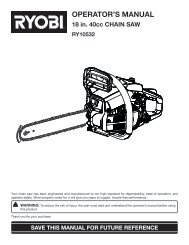
ASSEMBLYMITER SAWNUTLOCK WASHERflat WASHERSAW MOUNTingBRACKET2 x 4SLOTCARRIAGE BOLTFig. 6n Install carriage bolts as previously described.n After making sure both brackets are parallel to each other,finger tighten all four nuts to hold in position.If the <strong>saw</strong> has holes that do not line up with the slots inthe <strong>saw</strong> mounting brackets:n Unplug the <strong>saw</strong> and lock <strong>saw</strong> arm in the down position.n Mount the <strong>saw</strong> to a mounting surface at least 1/2 in.thick using 5/16 hex head screws, washers, and nuts(not included).n Drill holes in the mounting surface to match the slots inthe <strong>saw</strong> mounting brackets.n Proceed with installation as previously described.NUTMITER SAWLOCK WASHERflat WASHERLOCK WASHERflat WASHERNUTMOUNTINGSURFACESAW MOUNTINGBRACKETSLOTCARRIAGE BOLTFig. 77
171623ASSEMBLYMOUNTING THE MITER SAW TO THE STANDSee Figures 8 - 9.n Lift the <strong>saw</strong> and bracket assembly, allowing the assemblyto tilt slightly toward your body.n While still tilted toward you, hook the front edge of thebracket assembly onto the front rail of the <strong>stand</strong>.WARNING:To avoid serious personal injury, make sure the curvedfront edge of the mounting brackets are securely seatedover the front rail before seating the other end of thebrackets. Failure to do so could cause you to lose controlof the <strong>saw</strong> mounting assembly, which could cause seriouspersonal injury.n Lower the bracket assembly to allow the rear edge of thebracket to seat fully over the rear rail.n Lock the brackets in position by lowering the lockinglevers.NOTE: Continue to hold the mounting bracket assemblywith one hand until both levers are securely locked.n Check position and adjust, if necessary, to make surethe weight of the <strong>saw</strong> is evenly balanced over the railsas shown in figure 9.n Ensure the <strong>saw</strong> is fully seated and locked in position, thensecurely tighten the four nuts holding the <strong>saw</strong> to the <strong>saw</strong>mounting brackets.To remove <strong>saw</strong> from <strong>stand</strong>:n Raise the locking levers to unlock the <strong>saw</strong> and mountingbracket assembly.n Lift away from the rear rail of the <strong>stand</strong> to disengage.n With the assembly tilted slightly toward you, lift the frontpart of the assembly to disengage from the front rail ofthe <strong>stand</strong>.10 112 1Fig. 8WARNING:The mounting brackets are designed to fit snugly over the <strong>stand</strong> rails. With the locking levers in the lowered (locked)position, you should not be able to remove the <strong>saw</strong> and bracket assembly from the rails. If the mounting brackets willnot fit over the rails, or if the mounting brackets can be removed from the rails when the levers are locked, remove fromthe <strong>saw</strong> and bracket assembly immediately and tighten the bracket adjustment screw as described in the Maintenancesection of <strong>this</strong> <strong>manual</strong>. Failure to heed <strong>this</strong> warning may result in serious personal injury.8
ASSEMBLYlowerlocking leversto secureto <strong>stand</strong>Fig. 9operationWARNING:Do not allow familiarity with tools to make you careless.Remember that a careless fraction of a second issufficient to inflict serious injury.WARNING:Always wear safety goggles or safety glasses with sideshields when operating tools. Failure to do so could resultin objects being thrown into your eyes, resulting inpossible serious injury.WARNING:Do not use any attachments or accessories not recommendedby the manufacturer of <strong>this</strong> tool. The use of attachmentsor accessories not recommended can resultin serious personal injury.APPLICATIONSYou may use <strong>this</strong> tool for the following purpose:• To provide a stable, secure work surface for a <strong>miter</strong><strong>saw</strong>9
123456789operationusing the extension railsSee Figure 10.Use the extension rails when working with largerworkpieces.To extend the rails:n Loosen the extension adjustment knob.n Extend the rail to the desired position.n Tighten the extension adjustment knob.building and installing an optionalworkshelfSee Figures 12 - 14.Use the following directions, if desired, to build a workshelffor the <strong>miter</strong> <strong>stand</strong>.Materials needed:n 9 x 20 in. plywood, 3/4 in. thickn 8 wood screws, 1-1/4 in. lengthn Drill and bit to drill and countersink screw holesBuilding the workshelf:n Make cuts as shown in the cutting diagram below.EXTENSIONRAILEXTENSIONADJUSTMENTKNOBFig. 100 9 8 7 6 5 4 3 2 1 0using the work stopsSee Figure 11.Raise the work stops whenever you need to make repetitivecuts of the same size. To avoid a greater risk of binding orpinching, do not use both work stops at the same time.To raise the work stops:10 11 12 13 14 15 16 17 18 19 20 21 22 23n Loosen the work stop adjustment knob.n Raise the work stop to the desired position.n Tighten the work stop adjustment knob.WORK STOPWORK STOPADJUSTMENTKNOBFig. 11Fig. 12n Cut the ends of the three 3/4 in. pieces so that two are6 in. long and one is 7-1/2 in. long.n Align the two 3/4 x 6 in. plywood strips vertically alongthe left and right sides of the 9 x 13 in. base, making surethe front edges are flush.n Pre-drill and countersink holes for screws in each of thestrips as shown in figure 10; install screws.NOTE: Locate the screws at least 2 in. away from thebottom corners of the assembly.10
operationn Insert the 3/4 x 7-1/2 in. plywood strip horizontally betweenthe 6 in. strips, making sure the long edge is flushwith the base.n Pre-drill and countersink two holes; install screws.NOTE: The corners of the shelf can now be <strong>miter</strong>ed, ifdesired, to remove sharp edges.n Place the 3-1/2 x 9 in. piece of plywood horizontally1-3/4 in. above the vertical plywood strips. Make surethe left and right edges of the wood are flush with thesides of the base.n Pre-drill and countersink two holes in the center of woodas shown.Installing the workshelf:n Remove the 3-1/2 x 9 in. plywood and insert shelf betweentop and bottom rails of <strong>miter</strong> <strong>stand</strong> until edge of verticalstrips touch <strong>miter</strong> <strong>stand</strong> front rail.n Place the 3-1/2 x 9 in. plywood between the front andback rails of the <strong>miter</strong> <strong>stand</strong>. Re-align the pre-drilled holesin the top piece with the pre-drilled holes in the base ofthe shelf.n Install screws in pre-drilled holes to secure shelf.6"Fig. 131-3/4 in. WOODSCREWSbackrail3-1/2 x 9 in.plywoodfrontrailverticalstripshelf baseFig. 1411
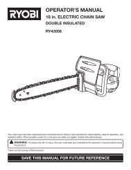
maintenanceWARNING:When servicing, use only identical replacement parts.Use of any other parts may create a hazard or causeproduct damage.WARNING:Always wear safety goggles or safety glasses with sideshields during power tool operation or when blowingdust. If operation is dusty, also wear a dust mask.To adjust:n Use a wrench to slightly loosen the nut.n Turn the screw with a phillips screwdriver. Rotate clockwiseif the bracket assembly needs to be tightened orcounterclockwise if the assembly needs to be loosened.n Install the bracket on the <strong>miter</strong> <strong>stand</strong> rails and lower thelocking lever to check the adjustment.n When the correct position is achieved, wrench tightenthe nut to secure.n Repeat with the second mounting bracket.GENERAL MAINTENANCEAvoid using solvents when cleaning plastic parts. Mostplastics are susceptible to damage from various types ofcommercial solvents and may be damaged by their use. Useclean cloths to remove dirt, dust, oil, grease, etc.SawmountingbracketwrenchWARNING:Do not at any time let brake fluids, gasoline, petroleumbasedproducts, penetrating oils, etc., come in contactwith plastic parts. Chemicals can damage, weaken ordestroy plastic which may result in serious personalinjury.bracket ADJUSTMENT SCREWSee Figure 15.Mounting brackets are designed to fit snugly over the <strong>stand</strong>rails. With the locking levers in the lowered (locked) position,you should not be able to remove the <strong>saw</strong> and bracket assemblyfrom the rails. If the <strong>saw</strong> and bracket assembly canbe removed from the rails when the levers are locked, thebracket adjustment screws need to be tightened. If the <strong>saw</strong>and bracket assembly will not fit over both rails, the bracketadjustment screws needs to be loosened.NOTE: The <strong>saw</strong> should be removed from the mountingbrackets before attempting to tighten or loosen the bracketadjustment screws.nutBRACKETADJUSTMENTSCREWscrewdriverFig. 15To purchase additional <strong>saw</strong> mounting bracket assemblies (part no. A000220601),call <strong>Ryobi</strong> customer service at 1-800-525-2579.ONE WORLD TECHNOLOGIES, INC.1428 Pearman Dairy Road, Anderson, SC 29625Phone 1-800-525-2579www.ryobitools.com983000-7109-24-08 (REV:02)