ITP Metal Casting: Advanced Melting Technologies: Energy Saving ...
ITP Metal Casting: Advanced Melting Technologies: Energy Saving ...
ITP Metal Casting: Advanced Melting Technologies: Energy Saving ...

Create successful ePaper yourself
Turn your PDF publications into a flip-book with our unique Google optimized e-Paper software.
<strong>Advanced</strong> <strong>Melting</strong> <strong>Technologies</strong>:<br />
<strong>Energy</strong> <strong>Saving</strong> Concepts and Opportunities<br />
for the <strong>Metal</strong> <strong>Casting</strong> Industry<br />
November 2005<br />
BCS, Incorporated<br />
5550 Sterrett Place, Suite 306<br />
Columbia, MD 21044<br />
www.bcs-hq.com
<strong>Advanced</strong> <strong>Melting</strong> <strong>Technologies</strong>:<br />
<strong>Energy</strong> <strong>Saving</strong> Concepts and Opportunities for<br />
the <strong>Metal</strong> <strong>Casting</strong> Industry<br />
Prepared for <strong>ITP</strong> <strong>Metal</strong> <strong>Casting</strong><br />
by<br />
BCS, Incorporated<br />
November 2005
Acknowledgments<br />
This study was a collaborative effort by a team of researchers from University of<br />
Missouri–Rolla, Case Western Reserve University, and Carnegie Mellon University with<br />
BCS, Incorporated as the project coordinator and lead.<br />
The research findings for the nonferrous casting industry were contributed by Dr. Jack<br />
Wallace and Dr. David Schwam, while the ferrous melting technologies were addressed<br />
by Dr. Kent Peaslee and Dr. Richard Fruehan. BCS, Incorporated researched<br />
independently to provide an overview of the melting process and the U.S. metal casting<br />
industry. The final report was prepared by Robert D. Naranjo, Ji-Yea Kwon, Rajita<br />
Majumdar, and William T. Choate of BCS, Incorporated.<br />
We also gratefully acknowledge the support of the U.S. Department of <strong>Energy</strong> and Cast<br />
<strong>Metal</strong> Coalition (CMC) in conducting this study.<br />
Disclaimer<br />
This report was prepared as an account of work sponsored by an Agency of the United States<br />
Government. Neither the United States Government nor any Agency thereof, nor any of their<br />
employees, makes any warranty, expressed or implied, or assumes any legal liability or<br />
responsibility for the accuracy, completeness, or usefulness of any information, apparatus,<br />
product, or process disclosed, or represents that its use would not infringe privately owned rights.<br />
Reference herein to any specific commercial product, process, or service by trade name,<br />
trademark, manufacturer, or otherwise does not necessarily constitute or imply its endorsement,<br />
recommendation, or favoring by the United States Government or any Agency thereof. The views<br />
and opinions expressed by the authors herein do not necessarily state or reflect those of the<br />
United States Government or any Agency thereof.
Contents<br />
Executive Summary......................................................................................................................i<br />
1. Objective and Scope of the Study................................................................................................1<br />
2. Introduction ..................................................................................................................................1<br />
3. <strong>Melting</strong> Process Overview............................................................................................................3<br />
3.1 The <strong>Melting</strong> Process..............................................................................................................3<br />
3.2 <strong>Energy</strong> Efficiency of the <strong>Melting</strong> Process ..............................................................................6<br />
3.3 <strong>Melting</strong> Process Emissions....................................................................................................8<br />
3.4 Selecting Appropriate <strong>Melting</strong> Technology............................................................................9<br />
4. Current and Emerging <strong>Melting</strong> <strong>Technologies</strong> and Practices........................................................9<br />
4.1 Established <strong>Melting</strong> Furnaces .............................................................................................10<br />
4.1.1 Crucible Furnaces ........................................................................................................10<br />
4.1.2 Cupola Furnaces ..........................................................................................................10<br />
4.1.3 Electric Arc Furnaces ...................................................................................................13<br />
4.1.4 Immersion Heaters (Low-Temperature <strong>Melting</strong>) ..........................................................15<br />
4.1.5 Induction Furnaces.......................................................................................................15<br />
4.1.6 Reverberatory Furnaces...............................................................................................17<br />
4.1.7 Rotary Furnaces...........................................................................................................19<br />
4.1.8 Stack Furnaces ............................................................................................................20<br />
4.2 Experimental <strong>Melting</strong> Furnaces ...........................................................................................21<br />
4.2.1 Electron Beam <strong>Melting</strong> (EBM)......................................................................................21<br />
4.2.2 Immersion Heaters (High-Temperature <strong>Melting</strong>)..........................................................22<br />
4.2.3 Infrared Heating............................................................................................................23<br />
4.2.4 Microwave <strong>Melting</strong>........................................................................................................24<br />
4.2.5 Plasma Heating ............................................................................................................25<br />
4.2.6 Solar Furnaces .............................................................................................................25<br />
4.3 Heat Recovery Methods ......................................................................................................26<br />
4.3.1 Recuperators................................................................................................................26<br />
4.3.2 Refrigeration.................................................................................................................27<br />
4.3.3 Regenerators................................................................................................................27<br />
4.3.4 Thermoelectric Devices................................................................................................28<br />
4.4 Molten <strong>Metal</strong> Handling Systems ..........................................................................................28<br />
4.4.1 Dosing Furnaces ..........................................................................................................29<br />
4.4.2 Electro-Magnetic Pump Systems .................................................................................29<br />
4.4.3 Ladles ...........................................................................................................................30<br />
4.4.4 Launder Systems .........................................................................................................30<br />
4.4.5 Mechanical Circulating Pumps.....................................................................................31<br />
4.5 Fuel Combustion <strong>Technologies</strong>: Oxy-Fuel Burners.............................................................31<br />
4.6 Preheating Systems.............................................................................................................32<br />
4.6.1 Shaft Furnace...............................................................................................................32<br />
4.6.2 Twin Shell System........................................................................................................33<br />
4.7 Refractories .........................................................................................................................33<br />
4.8 <strong>Melting</strong> Schedule .................................................................................................................34<br />
5. Challenges to Adopting New <strong>Technologies</strong> ...............................................................................34<br />
6. Future Direction of Research: Potential <strong>Energy</strong>-<strong>Saving</strong> <strong>Technologies</strong>......................................36<br />
7. Conclusion .................................................................................................................................39<br />
Endnotes....................................................................................................................................42
Executive Summary<br />
The metal casting industry is one of the most energy-intensive manufacturing sectors with the<br />
melting process accounting for over half (55%) of its energy consumption. Although its high<br />
energy expenses have been a significant concern for metal casters, the industry continues to use<br />
melting technologies with poor energy efficiency. The purpose of this study is to explore “Grand<br />
Challenge” or breakthrough opportunities that might dramatically reduce melting energy and to<br />
identify potentially energy-saving R&D areas based on the findings. The study was conducted to<br />
guide the <strong>Metal</strong> <strong>Casting</strong> subprogram of the Industrial <strong>Technologies</strong> Program (an initiative of the<br />
U.S. Department of <strong>Energy</strong>, Office of <strong>Energy</strong> Efficiency and Renewable <strong>Energy</strong>) in pursuing its<br />
energy reduction goal. The scope of the study includes current and emerging melting<br />
technologies in the industry worldwide, along with experimental technologies, retrofits for<br />
existing systems, and best practices.<br />
The seemingly simple melting operation – heating metals to turn them into liquids for pouring –<br />
is actually complex, involving a series of steps that incur material and energy losses. These<br />
losses are attributable to several factors: undesired conduction, radiation and convection, stack<br />
loss (flue gases), and metal loss. The extent of the losses depends on the furnace design, the fuel<br />
used, and the method of imparting heat to the metals. Exhibit 1 compares the efficiency and<br />
metal loss for different types of furnaces. The low thermal efficiency of current furnaces calls for<br />
high-priority R&D to improve melting technologies.<br />
<strong>Melting</strong> Furnace<br />
Typical<br />
Capacities*<br />
Crucible (Gas) 15 lbs - 1.5 tons<br />
Common Use Melt Loss<br />
Thermal<br />
Efficiency<br />
Aluminum 4-6% 7-19%<br />
Magnesium 4-6% 7-19%<br />
Copper-base 2-3% 7-15%<br />
Cupola 100 lb/hr - 20 tons/hr Iron 3-12% 40-50%<br />
Direct Arc †<br />
1.5 tons -100 tons Steel 5-8% 35-45%<br />
Immersion (low temperature<br />
melting)<br />
1,600lb/hr Zinc N/A 63-67%<br />
Induction †<br />
Reverberatory<br />
Electric †<br />
2 lbs - 50 tons<br />
0.5 tons - 125 tons<br />
Gas 0.5 tons - 125 tons<br />
Aluminum 0.75-1.25% 59-76%<br />
Copper-base 2-3% 50-70%<br />
Magnesium 2-3% 59-76%<br />
Iron 1-2% 50-70%<br />
Steel 2-3% 50-70%<br />
Aluminum 1-2% 59-76%<br />
Zinc 2-3% 59-76%<br />
Aluminum 3-5% 30-45%<br />
Zinc 4-7% 32-40%<br />
Rotary N/A Aluminum N/A 35%<br />
Stack Melter (Gas) 1 ton/hr - 10 tons/hr Aluminum 1-2% 40-45%<br />
*Information received from communication with AFS<br />
Source: DOE/CMC http://cmc.aticorp.org/datafactors.html<br />
† The primary energy efficiencies of these furnaces are much lower (about one-third) than the listed efficiencies due to the use of<br />
electricity, which involves sizeable energy losses during generation and transmission.<br />
Exhibit 1: Efficiency and metal loss for different furnaces<br />
i
The U.S. metal casting industry, primarily consisting of small businesses (80% have
1. Objective and Scope of the Study<br />
The objective of this study was to explore the concepts of breakthrough technologies in melting<br />
metals that may dramatically reduce the energy consumption. The study will guide the Industrial<br />
<strong>Technologies</strong> Program’s (<strong>ITP</strong>) <strong>Metal</strong> <strong>Casting</strong> subprogram in pursuing high-value R&D<br />
opportunities for enhancing energy efficiency of the metal casting industry.<br />
The study was undertaken as part of <strong>ITP</strong>’s Grand Challenge mission, a strategy seeking dramatic<br />
improvements in industrial energy efficiency. The study aims to provide a preliminary concept<br />
definition of “Grand Challenge” opportunities in the context of advanced melting technologies. It<br />
accomplishes its purpose by examining current and emerging melting technologies and<br />
discussing their technical barriers to scale-up issues and research needed to advance these<br />
technologies. It identifies potential avenues for improving melting efficiency, lowering metal<br />
transfer heat loss, and reducing scrap and improving yield.<br />
The scope of the study includes ferrous and non-ferrous melting applications in the metal casting<br />
industry, both in domestic and international markets. Although, the report focuses on metal<br />
melting applications, the melting technologies and developments discussed in this report are in<br />
general applicable to all furnaces and molten material processes, including primary aluminum,<br />
secondary aluminum, glass, iron and steel, and other industries.<br />
2. Introduction<br />
<strong>Melting</strong> of metals, glass, and other materials has been a vital manufacturing process for several<br />
thousand years, producing molten liquids that can be poured and solidified into useful shapes.<br />
Although the basic process continues to be the same, the utility of cast products has come a long<br />
way. The process that created tools and exotic goods for only a privileged few in the Bronze Age<br />
contributes to components used in over 90% of manufactured goods in our society today. Since<br />
the dawn of the industrial age, the tremendous progress in the melting process equipment, the<br />
range of molten materials, the chemistry and thermal controls, and the complexity of the finished<br />
products has enabled cast components in building a vast variety of products – automobiles,<br />
power generators, railroad cars, oil pipelines, military hardware, medical instruments, etc. to<br />
name just a few.<br />
The energy efficiency of any foundry largely rides on the efficiency of the melting process – a<br />
multi-step operation where the metal is heated, treated, alloyed, and transported into die or mold<br />
cavities to form a casting. The melting process is not only responsible for the energy<br />
consumption and cost-effectiveness of producing the castings (Exhibit 3), but it is also critical to<br />
the control of quality, composition, and the physical and chemical properties of the final product.<br />
1
<strong>Melting</strong> is the most energy-intensive<br />
operation in metal casting industry,<br />
accounting for about 55% of the total<br />
energy use in foundries<br />
Source: 2004 <strong>Metal</strong> <strong>Casting</strong> Annual Report<br />
Exhibit 3: Process energy costs in<br />
metal casting<br />
<strong>Melting</strong> being highly energy intensive, the metal casting industry is one of largest spenders on<br />
energy in the U.S. manufacturing sector. The industry spent $1.2 billion in fuels and electricity<br />
purchases alone in 1998. The concern over the energy efficiency of processes has been growing<br />
with the recent rising costs of energy. The metal casting industry is specially impacted by the<br />
large price swings of natural gas as it is the industry’s largest energy source (Exhibit 4). Factors<br />
like increasing energy demands, compounded by spikes in energy costs from world events and<br />
natural disasters (like Hurricanes Katrina and Rita), will continue the upward trend in energy<br />
costs, pressing the need for developing energy-efficient solutions for the melting process.<br />
Source: 2004 <strong>Metal</strong> <strong>Casting</strong> Annual Report<br />
*The amount of electricity represents delivered energy<br />
Exhibit 4: <strong>Energy</strong> source in metal casting<br />
2<br />
Although the energy consumption in the<br />
melting process has been a significant concern<br />
in foundry operations, the industry continues<br />
to use melting technologies with low energy<br />
efficiencies. Studies have shown that by<br />
implementing best practice technologies, iron<br />
and aluminum melting can save approximately<br />
1.2 and 3 million Btu per ton respectively. 2<br />
Considering that iron and aluminum casting<br />
tonnages comprise more than 85% of the total<br />
casting tonnage, potential savings in melting<br />
these metals are substantial. In summary,<br />
striving to reduce energy consumption in<br />
melting ferrous and non-ferrous metals shows<br />
a promising path to lowering operating costs<br />
in foundries and, in turn, cutting down the<br />
production costs for the entire U.S.<br />
manufacturing sector.
3. <strong>Melting</strong> Process Overview<br />
The melting of any industrial metal used in manufacturing involves the following steps:<br />
1. Preparing the <strong>Metal</strong> and Loading – removing dirt and moisture and sometimes,<br />
preheating the charge material, such as scrap metal or ingot; and introducing solid charge<br />
into the furnace system<br />
2. <strong>Melting</strong> the <strong>Metal</strong> – supplying energy from combustion of fuels, electricity or other<br />
sources to raise the metal temperature above its melting point to a pouring temperature<br />
3. Refining and Treating Molten <strong>Metal</strong>s – introducing elements or materials to purify,<br />
adjust molten bath composition to provide a specific alloy chemistry and/or affect<br />
nucleation and growth during solidification<br />
4. Holding Molten <strong>Metal</strong> – maintaining the molten metal in molten state until it is ready<br />
for tapping<br />
5. Tapping Molten <strong>Metal</strong> – transferring the molten metal from the furnace to transport<br />
ladle<br />
6. Transporting Molten <strong>Metal</strong> – moving the molten metal to the point of use and keeping<br />
the metal in molten state until it is completely poured<br />
Material and energy losses during these process steps represent inefficiencies that waste energy<br />
and increase the costs of melting operations. Modifying the design and/or operation of any step<br />
in the melting process may affect the subsequent steps. It is, therefore, important to examine the<br />
impact of all proposed modifications over the entire melting process to ensure that energy<br />
improvement in one step is not translating to energy burden in another step.<br />
3.1 The <strong>Melting</strong> Process<br />
1. Preparing and Loading <strong>Metal</strong> for <strong>Melting</strong><br />
Preheating or drying the scrap or ingot is often practiced in many melting applications, especially<br />
those that involve iron or aluminum. It offers several benefits: removal of moisture and other<br />
volatiles from the charge, preventing the risk of an explosion in the furnace and inhibiting slag<br />
formation from absorption of hydrogen formed when hot aluminum comes in contact with<br />
moisture; reduction in melting energy requirements; and increase in the melting capacity of the<br />
furnace. Aluminum scrap (containers, sidings, etc.) requires removal of paint, lacquers,<br />
machining oils, and other contaminants. This removal is usually accomplished thermally.<br />
Preheating and contaminant removal are typically accomplished by natural gas heating. Some<br />
foundries employ preheating systems that reuse hot flue gases of the melting furnace to pretreat<br />
and preheat. A scrap decoater developed by <strong>Energy</strong> Research Company (ERCo) removes various<br />
organics found in scrap aluminum. 3 The scrap is decoated in a low-oxygen, controlled<br />
atmosphere rotary kiln. Hot gases enter the kiln’s center tube, flow parallel to the scrap, and<br />
vaporize the organics in the scrap in the kiln. The oxygen in the kiln is kept below the<br />
flammability limits of the organic components, avoiding combustion in the kiln. These systems<br />
recover energy that is otherwise lost in most operations.<br />
3
<strong>Energy</strong> can be lost during the loading process when the prepared materials are loaded into the<br />
furnace for melting. If batch furnaces are loaded cold, the melting operation becomes inefficient<br />
as the entire furnace mass must be heated along with the metal. Conversely, a continuously<br />
operated furnace offers greater efficiency, not requiring additional energy to heat up the furnace<br />
in each melting cycle. However, loading a hot furnace requires opening the furnace door or lid,<br />
which allows vast quantities of heat to escape by convective flow of hot gases and by radiation.<br />
Numerous techniques and systems have been developed to address this problem. These include<br />
side wells furnace where heat loss is minimized as molten metal circulates through the charge<br />
well and back into the hearth for reheating during the charging period of furnace cycle. 4 It has<br />
also been demonstrated that submerging the scrap into the molten bath for melting reduces metal<br />
lost to oxidation (particularly for aluminum).<br />
2. <strong>Melting</strong> the <strong>Metal</strong><br />
Furnaces operate in aggressive environments, where several components—molten metals,<br />
furnace linings, atmospheric gases, and products from combustion of fuels—coexist at extremely<br />
high temperatures. Several factors come into play besides the core ingredients of heat and metal<br />
as illustrated in Exhibit 5.<br />
<strong>Energy</strong> (natural gas,<br />
fuel, electricity, coke)<br />
Air<br />
Fluxes & Alloy Elements<br />
Base <strong>Metal</strong><br />
Exhibit 5: Schematic of melting process<br />
A melting furnace derives its heat from solid fuels (coke and breeze), natural gas, electricity, or<br />
other sources of energy. Furnaces vary in design, geometry, capacity productivity (melting rates),<br />
materials-of-construction, and mode of operation (batch or continuous). Other factors related to<br />
the energy source also affect the furnace design which include how the energy is transferred to<br />
the molten material, how combustion gases are removed, what refining and treating equipment<br />
must enter the furnace, how long the holding periods are, and how the molten metal will be<br />
tapped. The operating temperatures required in the furnace depend on the melting and pouring<br />
temperature of the materials being melted. They can range from about 350°C (650°F) for zinc<br />
alloys to 1,700°C (3,100°F) for alloy steels.<br />
3. Refining/Treating Molten <strong>Metal</strong>s<br />
<strong>Melting</strong><br />
Furnace<br />
<strong>Melting</strong><br />
Furnace<br />
350°C to 1,700°C<br />
350°C to 1,700°C<br />
Conductive, Convective,<br />
and Radiant Heat Losses<br />
Flue Gas<br />
Dross/Slag<br />
Molten <strong>Metal</strong><br />
Refining is the process of degassing the melt, removing undesirable solid phase (typically<br />
oxides), and trimming the alloy composition to be within desired limits. The molten metal stage<br />
4
offers a critical opportunity to refine and maximize the quality of the final casting. Therefore,<br />
processes such as alloying, degassing, filtration, fluxing, and grain refinement and modification<br />
are usually carried out in the liquid metal prior to casting. At this stage, the composition of the<br />
melt can be fine-tuned to the desired proportions by appropriate additions.<br />
Alloying elements with high vapor pressure and high reactivity at elevated temperatures, such as<br />
sodium, calcium and magnesium, tend to be depleted from the molten alloy with time and high<br />
temperature. Loss of these elements will affect the physical/mechanical properties of the castings,<br />
leading to increased scrap and waste.<br />
Gases that dissolve into the molten charge from the ambient air, combustion byproducts, and the<br />
furnace linings can also affect the quality of the final product. For example, molten aluminum<br />
has a high affinity for hydrogen formed when aluminum comes in contact with water vapor, a<br />
natural by-product from combustion and occurring naturally in the atmosphere. The hydrogen<br />
solubility increases with time and temperature. As aluminum solidifies, the dissolved hydrogen<br />
escapes imparting an undesirable porosity to the final product, a common problem at cast<br />
aluminum facilities. Degassing and filtering out solid inclusions, such as oxides, has, therefore,<br />
become a norm at U.S. casting facilities. Disposable ceramic filter is one of the current methods<br />
that reduces cost and improves the quality of the castings. Disposable ceramic filters are placed<br />
in the mold runner system to trap solid inclusions formed during melt transfer between the<br />
furnace and its entry into the mold cavity. Determining hydrogen content in aluminum alloys has<br />
also become common. Currently, ultrasound is being explored as a potential means in<br />
commercial operations to reduce the porosity. Continued development of better technologies is<br />
needed to monitor the quality of the molten metal economically.<br />
The current practice to control the composition of molten metal is expensive and time consuming.<br />
It requires taking a small sample of molten metal out of the molten bath and transporting it to a<br />
laboratory for chemical analysis. This creates a lag time between measured and actual<br />
composition, which can lead to excessive processing, increased energy use and emission, and<br />
off-spec product that may need to be down-graded or scrapped. ERCo has recently introduced<br />
Laser-Induced Breakdown Spectroscopy (LIBS) technology that employs a laser and a<br />
spectrometer to measure in-situ and in real time the constituents of the melt in a process furnace. 5<br />
Such technologies can reduce defects, increase furnace cycle times leading to continuous and<br />
semi-continuous operations, increase furnace life by diagnosing the state of the furnace, and<br />
increase automation of furnace operations.<br />
4. Holding Molten <strong>Metal</strong>s<br />
The molten metal is often held in a furnace before being poured or injected into molds to allow<br />
for a continuous supply of molten metal from the melting furnace with consistent composition<br />
and quality. This is especially important when the charge materials are composed of large<br />
amounts of low-quality metallic scrap with poor composition such as blends of consumer durable<br />
goods. Holding furnaces also help casters take advantage of the off-peak electricity hours to melt<br />
charges at reduced energy rates. However, the holding step in the melting process adds to<br />
melting inefficiencies because energy is utilized in holding the metal in its molten state. An ideal<br />
melting operation would melt metal into its liquid state and then transport that metal directly to<br />
the pouring lines, eliminating the need to hold the molten bath in a holding furnace.<br />
5
5. Tapping Molten <strong>Metal</strong>s<br />
Tapping is the process of removing the molten metal from the furnace and pouring it into ladles<br />
or molds. Tilting furnaces can pour molten metal directly into transfer ladles for casting or can<br />
transfer it to an adjacent holding furnace. A tilting furnace is ideally suited for providing a<br />
controlled and consistent metal flow safely and reliably with minimal harm to the melt quality.<br />
6. Transporting Molten <strong>Metal</strong>s<br />
After being tapped, the molten metal must be transported from the melting furnace to the holding<br />
furnace or the pouring lines. Different types of ladles are used to pour the molten metal into the<br />
mold cavities. These include bottom-pour, lip-pour, teapot, hand, bull, trolley, and crane. Ideally,<br />
transfer ladles are preheated to maintain the required pouring temperature at the pouring station.<br />
Some operations also practice “superheating” the melt, i.e., raising the temperature several<br />
hundred degrees above the pouring temperature, to achieve the same result. The transfer ladle<br />
capacities can range from 100 pounds to 35 tons or higher depending on the foundry’s<br />
production capacity.<br />
Transfer ladles consume significant energy because they require preheating and/or superheating<br />
the melt to maintain the desired pouring temperature. Additionally, substantial radiation loss can<br />
occur from the top and the sides of the ladle. Researchers at University of Missouri–Rolla<br />
noticed that the radiation losses for steel occur predominantly from the ladle sides because the<br />
slag cover acts as a natural insulator for the top surface. This finding stresses the need for<br />
improved refractory material for steel foundry transfer ladles.<br />
3.2 <strong>Energy</strong> Efficiency of the <strong>Melting</strong> Process<br />
The energy efficiency of the melting process is calculated by dividing the amount of theoretical<br />
energy needed to melt a metal and raise it to its pouring temperature by the actual amount of<br />
energy consumed in melting, treating, holding and handling the material.<br />
<strong>Energy</strong> Efficiency =<br />
Theoretical <strong>Energy</strong> Required<br />
Actual <strong>Energy</strong> Used<br />
Several factors affect the energy efficiency of a furnace:<br />
X 100<br />
1. Stack Losses: Stack losses are due to the heat discharged via flue gases and partially<br />
combusted gases. These represent the greatest energy loss in a fuel-fired furnace. The amount<br />
of energy lost is related to the stack gas temperature, gas mass, and composition.<br />
Thermodynamically, the temperature will always be in excess of the molten metal holding<br />
temperature. There is no way to design a furnace with the exiting gas temperature equal or<br />
less than the metal temperature. The furnace design can control the mass of gas that exits a<br />
furnace system, which is a function of the oxygen required to combust the furnace fuel.<br />
When air is used as the source of oxygen, the mass of exiting gases is nearly 21 pounds for<br />
each pound of fuel consumed. Pure oxygen would lower the mass of exiting gas to only 5<br />
pounds. Oxygen enrichment systems offer a significant opportunity to reduce the mass of hot<br />
exiting gas, as well as provide hotter flame temperature, which will lead to higher heat<br />
6
transfer rate and reduced time required to melt the charge. This, in turn, would increase the<br />
productivity and cut down the energy lost through the furnace walls. The ratio of air (or<br />
oxygen) to fuel in the furnace is also crucial. Too little air will result in unburnt and wasted<br />
fuel, while excess air will waste energy in heating the additional air mass. Flue stack energy<br />
can be recovered to some degree if a regenerator or a recuperator is placed in the path of the<br />
exhaust gases and used to heat the incoming combustion air or if the flue gases can be used to<br />
preheat the metal charge.<br />
2. <strong>Metal</strong> Loss: The surface of the molten metal can oxidize leading to substantial metal loss in<br />
the form of “slag” (term associated with ferrous alloys such as steel) or “dross” (in case of<br />
non-ferrous alloys such as aluminum). This lost metal must be replaced by new metal. The<br />
extent of the metal loss depends upon the affinity of the molten constituents for oxygen and<br />
the melting method. These losses are the highest in aluminum-magnesium alloys. 6 Molten<br />
metal loss is a serious issue when considering a furnace design. If the metal losses are high,<br />
the overall operation would be inherently inefficient and uneconomical.<br />
3. Radiation Losses: These occur as energy emitted from hot furnace and enclosure surfaces.<br />
When the furnace lid or door is opened for charging and tapping, radiation heat losses<br />
increase significantly. Radiation losses from an uncovered bath can reach up to130 kWh/hr<br />
(0.44 MBtu/hr) for an iron furnace with a 10-ton capacity.<br />
4. Conduction and Convection Losses: These losses can be controlled by using suitable<br />
refractory materials and maintaining a tight fit between the lid and the furnace body.<br />
5. Slag/Dross Removal: This can also contribute to energy loss. The extent depends on the<br />
temperature, the composition of the slag/dross, the technique used and how long the furnace<br />
is left open to remove the slag/dross. This loss is not substantial to affect the overall furnace<br />
efficiency, unless huge amounts of slag/dross are removed.<br />
The extent of these energy losses vary depending on the furnace design, operating practices,<br />
metals being melted and the source of energy being used. Exhibit 6 displays a breakdown of the<br />
energy consumption (different forms of energy loss and energy used in melting) for ferrous and<br />
non-ferrous melting.<br />
<strong>Energy</strong> Spent Ferrous <strong>Melting</strong> 7,8<br />
Non-Ferrous <strong>Melting</strong> 9,10<br />
Stack Losses (flue gases) 0 to 50% 35 to 50%<br />
Dross/Slag 0 to 10% 10 to 20%<br />
Radiation/Conduction/Convection 10 to 50% 0 to 10% *<br />
Molten <strong>Metal</strong> 40 to 80% †<br />
10 to 40%<br />
* Heat lost from walls<br />
† The ferrous melting efficiency is much lower than listed due to the use of electricity, which involves sizeable energy losses<br />
during generation and transmission.<br />
Exhibit 6: Heat loss through various modes and useful energy<br />
7
3.3 <strong>Melting</strong> Process Emissions<br />
Emissions formed as a result of the melting process are a concern in improving melting<br />
technology. Emissions are primarily generated from two sources during the melting process:<br />
• Emissions related to energy supply<br />
• Emissions related to preparing, refining and treating<br />
<strong>Energy</strong> supply emissions are the result of combustion either at the melting facility or at the plant<br />
generating the electric power used in melting. Preparing, refining and metal treating also result in<br />
emissions that are related to the raw materials brought into the process.<br />
Sixty percent of the metal casting industry’s energy requirements is supplied by natural gas and<br />
27% from electricity. The remainder includes other fuel sources such as coke and breeze. 11<br />
Natural gas is the cleanest burning of all the fossil fuels. Composed primarily of methane, the<br />
main products of the combustion of natural gas are carbon dioxide (CO2) and water vapor.<br />
Emissions of nitrogen oxides (NOx), sulfur dioxide (SO2) and particles from natural gas<br />
combustion are one to three orders of magnitude lower than that for coal and fuel oil, as shown<br />
in Exhibit 7.<br />
Emissions<br />
(pounds per billion Btu of energy input)<br />
Natural Gas Oil Coal<br />
Carbon Dioxide 117,000 164,000 208,000<br />
Carbon Monoxide 40 33 208<br />
Nitrogen Oxides 92 448 457<br />
Sulfur Dioxide 1 1,122 2,591<br />
Particulates 7 94 2,744<br />
Mercury 0 0.007 0.016<br />
Source: EIA - Natural Gas Issues and Trends 1998<br />
Exhibit 7: Fossil fuel emission levels<br />
<strong>Melting</strong> systems that use electricity do not produce onsite emissions related to the actual heating<br />
of materials. However, significant offsite emissions are produced in the generation and<br />
transmission of electricity. These offsite emissions are directly related to the fuels used to<br />
produce electricity. The major fuels for electric power generation are coal, producing about 51%<br />
of the electricity in the United States; nuclear, producing 20%; and natural gas, producing 6%.<br />
The low efficiency of electricity generation and transmission is also an important factor to<br />
consider in energy and emission analyses. It requires about 10,600 Btu of fuel to produce 1 kWh<br />
(3,412 Btu) of electricity. When coke is used as a fuel and a carbon source in melting furnaces<br />
(e.g., for iron and steel melting), emissions consist mainly of CO2 and CO from incomplete<br />
combustion and to a lesser extent, NOx and SOx.<br />
Emissions related to preparing, refining, and treating are generated in varying amounts<br />
depending on the degree of processing that must be accomplished. These emissions result from<br />
the dirt, moisture, and metallic impurities in the metal charge; erosion and corrosion products<br />
from the metal’s contact with the refractory; and the addition of alloying elements and treatment<br />
chemicals used for removal of impurities and dissolved gases.<br />
8
3.4 Selecting Appropriate <strong>Melting</strong> Technology<br />
Industrial operations have to address a broad range of considerations that have a direct effect on<br />
their “bottom line” when faced with the choice of melting technologies. These factors include:<br />
• Space availability (floor space & height) • Capital investment<br />
• Type and variety of alloys to be melted • Quantity of the metal required<br />
• Fluctuations in metal demand during operation • Alloying requirement<br />
• Quality of the metal • Operating costs, especially in labor<br />
• Quantity of dross/slag • Reliability of the equipment<br />
• Emissions and environmental considerations • Durability of the furnace<br />
• Maintenance requirements<br />
Since each foundry may attribute a different priority to each one of these factors, there is no<br />
“one-size-fits-all” decision in the selection of melting technologies. <strong>Energy</strong> efficiency is not<br />
necessarily the only significant criterion in selecting melting equipment. Where energy costs are<br />
high (e.g., in Europe), energy efficiency has been an operating priority for many years. For<br />
example, stack furnaces are more common than reverberatory furnaces for melting aluminum in<br />
Europe. However, in the United States, 95% of aluminum is melted in gas reverberatory<br />
furnaces, which operate with energy efficiency of 20-30% but require lower capital cost and<br />
provide easier operation and maintenance than stack melters.<br />
A furnace design must meet some requirements to provide for an efficient melting process.<br />
These requirements include the ability to produce high-quality metal, to accurately control bath<br />
temperatures, to minimize metal losses, and to meet environmental concerns, while maintaining<br />
high energy efficiency. Although the cost of fuels, metals and labor are constantly changing<br />
variables, energy efficiency will always be an important consideration, especially in the face of<br />
the current trend of rapidly rising energy costs. Improving efficiency of melting, while<br />
addressing all other aspects of the operation, is critical in keeping the metal casting industry<br />
competitive. 12<br />
4. Current and Emerging <strong>Melting</strong> <strong>Technologies</strong> and<br />
Practices<br />
This section of the report describes different types of melting technologies that are currently used<br />
in the metal casting industry. It discusses their benefits, technical barriers, and scale-up issues,<br />
and examines advances in furnace technologies that improve energy efficiency and reduce melt<br />
loss. Non-conventional melting technologies are included even though their practical application<br />
may be limited, as they offer alternative approaches and add to our knowledge base in the<br />
melting technology field. Additionally, the more practical energy-saving opportunities are<br />
described, such as retrofits for existing furnace systems, changes in fuel source, and best<br />
practices.<br />
9
4.1 Established <strong>Melting</strong> Furnaces<br />
4.1.1 Crucible Furnaces<br />
A crucible furnace is the least expensive melting method preferred for melting small volumes of<br />
non-ferrous metals. They are popular in jobbing foundries and die casting shops because they are<br />
easy to tap and charge with another alloy. There is no direct impingement of the flame on the<br />
metal, and the heat loss to the outside is limited by the refractory walls. 13 However, the energy<br />
efficiency of the crucible furnace is low at 7 to 19%, with over 60% of the heat loss attributed to<br />
radiation. The life of the crucible furnace is short and temperature control is difficult.<br />
Source: Case Western Reserve University<br />
Exhibit 8: Radiant panel installed in gas<br />
crucible furnace<br />
Radiant energy transmission in a gas<br />
crucible furnace can be minimized by<br />
installing a radiant panel lining, 14 which<br />
combines a dense, high-alumina radiant<br />
panel with low thermal mass insulation<br />
back-up material. The radiant panels<br />
incorporate a series of raised nodules<br />
(Exhibit 8). This design creates a high<br />
surface area that promotes radiant energy<br />
transfer to the outer surface of the crucible.<br />
Backing up the non-insulating radiant panel<br />
with low thermal conductivity refractory<br />
insulation products allows the outside<br />
surface of the furnace to stay cooler,<br />
reducing heat loss through the sides of the<br />
furnace and increasing the efficiency of the furnace. The pre-fired radiant panels do not require<br />
mixing or drying-out period as in castable linings, nor do they require forms to be placed and<br />
removed. It is estimated that the technology can improve crucible furnace efficiency by 30% and<br />
improve the melt rates. A benchmarking study by Case Western Reserve University is currently<br />
underway to substantiate these claims.<br />
4.1.2 Cupola Furnaces<br />
The cupola furnace is a vertical shaft furnace used primarily for melting cast iron (Exhibit 9). It<br />
is similar in principle (except in scale) to the blast furnace used for chemically reducing metal<br />
oxides in the production of iron, zinc and lead. Typically, cupola melting is used in large tonnage<br />
foundries (e.g., plants producing cast iron pipes or automotive parts). In fact, 60% of iron casting<br />
tonnage is melted in a cupola. The cupola is ideal for melting cast iron because the molten<br />
droplets of metal directly contact the coke and flux during their descent, saturating the liquid iron<br />
with carbon and refining the metal product. This structure allows the cupola to melt nearly<br />
almost all ferrous scrap. The energy efficiency of cupola melting ranges from 40 to over 70%.<br />
Although the concept of cupola melting has not changed in recent years, best practices include<br />
many new technologies to improve energy efficiency and productivity.<br />
10
Source: <strong>Metal</strong>s Handbook by ASM International (pg. 753)<br />
Exhibit 9: Sectional view of conventional (non-water cooled) & water-cooled cupolas<br />
(The conventional type is refractory lined. Water-cooled types incorporate either an enclosed jacket<br />
or an open cascade flow.)<br />
The potential areas of improvement in cupola melting are as follows.<br />
Refractories: Solid materials charged into the top of the cupola slowly move downward as the<br />
heat melts the charge. This movement creates abrasive conditions which wears the refractories<br />
rapidly. The conventional designs of cupolas used refractory-lined shells and were typically<br />
limited to short periods of operation (~1 week) before requiring refractory relining or<br />
repairing/maintenance. Water-cooled cupolas use a steel internal surface with little to no<br />
refractory materials, reducing maintenance and extending the continuous operating time to over<br />
two weeks. However, water cooling results in significantly greater energy losses requiring higher<br />
charge rates of coke per ton of iron produced. This problem has led to improved designs using a<br />
smaller volume of water on the outside of the shell in addition to a thin refractory lining. The<br />
steep temperature gradient on the inside cupola wall maintains a thin layer of refractory<br />
throughout the melting campaign. The aggressive melting conditions in modern cupolas has<br />
resulted in the development of new cement castables and spray monolithic linings (requiring no<br />
forms) which provide superior properties in terms of wear, heat transfer, and ease of installation<br />
and repair. 15<br />
Air Blast Preheating: Hot blast operations offer several advantages like energy savings, lower<br />
sulfur pick-up, and higher carbon pick-up. However, these benefits are substantially reduced if<br />
the blast air temperature is below 400°C (750°F). Therefore, secondary gas/oil firing is often<br />
used to supplement recuperative waste gas systems to produce high-temperature blast air<br />
consistently. Some new cupola installations with efficient off-gas combustion systems (which<br />
utilize the energy associated with CO emissions) and waste heat recuperators preheat the hot<br />
11
last air up to 650 o C (1,200°F). 16 Also, some plants dehumidify the hot blast air as it reduces the<br />
rate of coke consumption.<br />
Oxygen Enrichment of Blast: Plants using oxygen enrichment typically add oxygen at volumetric<br />
flow rates of 2 to 20% of the blast air to increase the temperature and the melt rate. Oxygen is<br />
usually introduced at the tuyere level of the cupola. Oxygen enrichment is common in the United<br />
States and Europe, especially in large cupolas. However, the process is not widely used in<br />
smaller shops because oxygen enrichment is difficult to justify in terms of cost (of oxygen).<br />
Supplemental <strong>Energy</strong>: Although coke is the main source of energy for cupola melting, the use of<br />
supplemental energy is a promising way for improving energy and operational efficiency of<br />
cupola melting. Oxygen-fuel burners with dust injection systems provide a method of recycling<br />
plant-generated residues (cupola dust, finishing dust, and sand reclamation dust) while increasing<br />
the cupola volume for melting, leading to better energy efficiency. 17 Injection of powdered<br />
alloying materials also provides a method of quickly adjusting the iron chemistry.<br />
Intelligent Control: The harsh interior of the cupola has made it difficult to introduce the sensors<br />
required to measure and control process variables.<br />
Therefore, many cupolas are operated in open-loop<br />
mode. Recently, computer models have become<br />
available, including neural network models, to provide<br />
rapid estimates of process variables for use in<br />
automated control schemes. Computer control of the<br />
cupola process lowers material and processing costs,<br />
reduces scrap and improves quality.<br />
Plasma-Fired Cupola: This technology was developed<br />
by Westinghouse Electric Corporation with<br />
participation from several major U.S. foundries. 18 As<br />
shown in Exhibit 10, a plasma torch is installed in the<br />
tuyere zone of the cupola where blast air is supplied<br />
and mixed with the plasma torch flow in a special<br />
mixing chamber. This arrangement is reported to<br />
increase productivity (up to 60%) from decoupling of<br />
the combustion process and total heat input to the cupola. Air blast velocity and penetration can<br />
be lower due to the high-energy output of the plasma torch, resulting in lower cost of air<br />
pollution control and less dependency on premium quality coke. Smaller-sized anthracite coal<br />
can be used without a negative effect on the melt rate or the composition. Since the conditions in<br />
the furnace are less reducing, charge material can be very thin and include materials such as cast<br />
iron borings without oxidation loss of silicon. A commercial-scale plasma cupola was built with<br />
1.5 MW plasma torch in each of the six tuyeres at General Motors’ Powertrain Plant in Defiance,<br />
Ohio. 19 Center for Material Production<br />
Exhibit 10: Plasma cupola<br />
This plant demonstrated that a plasma-fired cupola could be operated economically and<br />
melt up to 75% iron borings.<br />
12
Cokeless Cupola: Iron is melted in this cupola<br />
using fuels such as natural gas, propane, diesel<br />
oil or pulverized coal in place of coke. Although<br />
invented over 30 years ago, only a few large<br />
foundries in Europe and India have adopted the<br />
technology. A water-cooled grate supports<br />
specially developed refractory spheres, which<br />
act as heat exchangers in a cokeless cupola<br />
(Exhibit 11). Below the grate are burners, which<br />
are operated to impart partially reducing<br />
conditions inside the cupola to reduce oxidation<br />
losses. The hot gases from the burners maintain<br />
the bed of spheres at high temperature, and<br />
preheat and melt the scrap in the shaft. The<br />
metal is superheated in passing through the bed<br />
and is then collected in the well prior to tapping.<br />
A carburizer is continually injected into the well<br />
13<br />
Source: DOE, EERE <strong>Energy</strong> Environmental Profile of the<br />
U.S. <strong>Metal</strong> <strong>Casting</strong> Industry<br />
Exhibit 11: Cokeless gas-melting<br />
cupola<br />
to give the correct carbon analysis. Elimination of coke decreases the CO content in the waste<br />
gas to 1%, indicating more efficient energy use when compared with the 12 to 20% CO emission<br />
typical in a conventional cupola. Use of cokeless cupolas simplifies the emission control system<br />
and results in lower sulfur content in metal and reduced slag production.<br />
Cokeless cupolas are typically operated at relatively low tapping temperatures of about 1,400 o C<br />
(2,550°F) to extend the refractory life, followed by superheating and re-carburization in an<br />
electric furnace. Cokeless cupolas duplexing through electric furnaces are presently in use in<br />
Germany, Spain, Japan, Austria, and Korea. In terms of energy efficiency, a typical cold blast<br />
cupola averaging 12% coke consumption and 1,450°C (2,640°F) tap temperature effectively<br />
utilizes 40% of the energy input while a cokeless cupola with natural gas consumption of 50<br />
Nm 3 /t (1,770Nft 3 /t) and an iron temperature of 1,380°C (2,520°F) utilizes 72% of the available<br />
energy. 20<br />
4.1.3 Electric Arc Furnaces<br />
Steel automobile shredded scrap with high residual elements and virgin iron raw materials, such<br />
as direct reduced iron, are difficult to melt efficiently in a cupola or coreless induction furnace.<br />
Cupola melting requires clean steel scrap and coke, materials that are becoming increasingly<br />
scarce and expensive. Electric arc furnaces are well suited for these purposes. Almost 87% of the<br />
electric arc furnaces are used to melt steel (or iron and steel) and 13% to melt iron. 21<br />
Electric arc furnace uses electrodes that are lowered to strike an arc on the cold scrap; the<br />
electrical system automatically controls the level of the electrode, lifting and lowering each<br />
individual electrode according to the electrical settings. The arc provides heat by radiation and<br />
current resistance (through the metal) to melt the scrap. 22 An intrinsic advantage of electrical<br />
heating is the lower metal loss.
Source: DOE, EERE <strong>Energy</strong> Environmental Profile of the U.S. <strong>Metal</strong> <strong>Casting</strong> Industry<br />
Exhibit 12: Electric arc furnace<br />
Nearly all furnaces are three-phase AC direct arc with three electrodes in a dome-shaped<br />
refractory roof (Exhibit 12). The hearth and sidewalls are typically lined with bricks, monolithic<br />
materials, or a combination of both. Acid refractories (silica-based), basic refractories<br />
(magnesite-based), and in some cases, neutral refractories (alumina-based) are used to line the<br />
furnace sidewalls, hearth, and roof. All major additions are made to the furnace through the roof<br />
by swinging the roof out of the way and charging scrap, fluxes, and carbon from loaded buckets.<br />
Most foundry steel is melted in electric arc furnaces. <strong>Energy</strong> losses from the surface of the bath<br />
are large due to the large surface area to volume ratio of the furnace resulting in significant<br />
energy losses during delays in the operation. In addition, the large surface area of the furnace<br />
results in large losses through the refractory walls, hearth, and roof. Nearly all steel foundries<br />
blow oxygen into the bath after most of the scrap is melted which generates “chemical energy”<br />
from exothermic decarburization, assisting in the melting process. Some operations use<br />
additional sources of chemical energy to decrease tap-to-tap time.<br />
The first continuous submerged direct current electric arc (Contiarc) furnace for melting iron was<br />
installed by American Cast Iron Pipe Company (ACIPCO) in July 2001. The key to the electric<br />
arc furnace’s molten iron production is that it can tap, charge, and arc continuously and<br />
simultaneously. As a result, the power does not need to be turned off to tap or charge the furnace.<br />
The submerged arc design and the continuous nature of the furnace operation make it more<br />
energy efficient than the cupola. In addition, the furnace can either take low-grade steel scrap,<br />
direct reduced iron and/or hot briquette iron and combine it with coal and silica to melt steel or<br />
smelt iron in the same furnace system, producing 80 ton/hour.<br />
14
4.1.4 Immersion Heaters (Low-Temperature <strong>Melting</strong>)<br />
Immersion furnaces or heaters are currently used<br />
for low-temperature melting of zinc. The heat is<br />
generated by combustion or electrical resistance<br />
inside a tube submerged in molten material (Exhibit<br />
13). The heat is efficiently transmitted to the molten<br />
material through the wall of the tube by conduction.<br />
Combustion gases are never exposed to the molten<br />
metal, reducing oxidation losses and enhancing heat<br />
transfer to the molten metal. 23 The efficiency of a<br />
zinc immersion furnace is high at 63 to 67% 24 and<br />
provides melting rates of up to 1,600 lbs/hr.<br />
Immersion heat tubes are typically made of metallic<br />
materials that have high thermal conductivity and<br />
are coated with ceramic or cement materials to<br />
resist corrosive attack by the molten metal. When<br />
melting aluminum or other higher-temperature-<br />
Source: <strong>Metal</strong>s Processing Advisor<br />
www.energysolutionscenter.org<br />
Exhibit 13: Immersion heater<br />
melting materials, heavier ceramic coatings are applied because these molten materials act more<br />
aggressively on the tubes. The ceramic coatings, however, act as a thermal barrier and lower the<br />
productivity of the immersion heater. The mechanical demands on ceramic-coated metallic tubes<br />
are also very high. These tubes must be structurally strong to survive in an industrial<br />
environment and must be able to operate under frequent thermal cycling. A small crack in the<br />
coating can lead to rapid destruction of the tube and lost productivity. Higher-temperature<br />
melting furnaces utilizing immersion tubes are still considered experimental, and efforts have<br />
been made to develop more robust and protective tubes (see section 4.2.2).<br />
4.1.5 Induction Furnaces<br />
Induction furnaces have increased in capacity to where modern high-power-density induction<br />
furnaces are competing successfully with cupola melting (Exhibit 14). There are fewer chemical<br />
reactions to manage in induction furnaces than in cupola furnaces, making it easier to achieve<br />
melt composition. However, induction melting is more sensitive to quality of charge materials<br />
when compared to cupola or electric arc furnace, limiting the types of scrap that can be melted.<br />
The inherent induction stirring provides excellent metal homogeneity. Induction melting<br />
produces a fraction of the fumes that result from melting in an electric arc furnace (heavy metal<br />
fumes and particulate emissions) or cupola (wide range of undesirable gaseous and particulate<br />
emissions as a result of the less restrictive charge materials). 25<br />
15
Source: DOE, EERE <strong>Energy</strong> Environmental Profile of the U.S. <strong>Metal</strong> <strong>Casting</strong> Industry<br />
Exhibit 14: Schematic of induction furnace<br />
A new generation of industrial induction melting furnaces has been developed during the last 25<br />
years. 26,27,28,29 The development of flexible, constant power-tracking, medium-frequency<br />
induction power supplies has resulted in the widespread use of the batch melting methods in<br />
modern foundries. The batch-melting furnace empties the furnace after each cycle, reducing the<br />
power required for holding. These power units incorporate heavy-duty silicon-controlled<br />
rectifiers that are able to generate both the frequency and the amperage needed for batch melting<br />
and are able to achieve electrical efficiency levels exceeding 97%, a substantial improvement<br />
over the 85% efficiency typical of induction power supplies of the 1970s. The new designs allow<br />
maximum utilization of furnace power throughout the melting cycle with good control of stirring.<br />
Some of the largest commercial units are capable of melting at nearly 60 tons per hour and small<br />
furnaces with very high power densities of 700 to 1,000 kWh/ton can now melt a cold charge in<br />
30 to 35 minutes.<br />
These newer power supplies improve the overall melting efficiency and furnace production at<br />
lower operation and fixed costs. Electrical efficiency is improved by the higher electrical<br />
resistance of the solid charge material compared with that of the molten metal. <strong>Melting</strong> in<br />
batches without a liquid heel allows for melting of lower-quality (less expensive) scraps<br />
containing moisture or oil residues without having to dry them first. At the same time, refractory<br />
materials in linings have improved due to new materials and reduced average thermal stress. 30<br />
Induction furnaces have benefited from improvements in the following areas:<br />
Scrap Charging Systems: Scrap sorting and charging systems that achieve higher density<br />
charges show increase in efficiency through increase in coil efficiency and shortening of melting<br />
time. Furnace loading time has been shortened by utilizing special vibrating conveyor systems<br />
designed to directly feed scrap into the furnace during melting. <strong>Melting</strong> time is reduced by<br />
preheating the charge before loading to remove moisture and residual oil.<br />
Furnace Designs: Newer furnaces with more efficient and larger power supplies (kWh capacity<br />
per ton) reduce energy consumption. Dual-output power supplies, increasing the production and<br />
efficiency of a single power supply, have been shown to be effective in melting steel. In addition,<br />
new high power density furnaces have been designed with heavy copper tubing, rigid structural<br />
16
elements, advanced coil insulation, and noise reduction. Wide-bodied furnaces for large capacity<br />
operations allow loading of larger scrap and give better access for slag removal.<br />
Furnace Covers: The use of furnace cover is critical to energy efficiency once the metal is<br />
molten. The simplest system is to keep a slag on the molten metal, reducing radiation losses from<br />
the top surface. Higher efficiency systems include furnace lids constructed from refractories or<br />
ceramics with low thermal conductivity, which reduces conduction and radiation heat losses.<br />
Harmonics Controls: Harmonics problem, or feedback of electrical equipment on the power<br />
source, can be caused by the high power of the furnace power supplies. These power interface<br />
problems include low-power factor, high-frequency harmonics, line voltage notching, and interharmonic<br />
distortions. Special technologies and equipments have been developed to minimize the<br />
negative influence of induction furnaces on the power supply. Computerized controls and<br />
diagnostic systems are available to provide close control of the melting operation and reduce the<br />
chances of accidental overheating. A typical control system uses information from load cells for<br />
the weight of the furnace charge and thermocouple readings for melt control optimization.<br />
Multiple-Output Power Supplies: Dual-output or “butterfly” operations utilize a single power<br />
supply and two furnaces with mechanized or electronic switching. This results in continuous and<br />
completely controllable power to two furnaces at the same time. Recently, multiple-output power<br />
units with three or more outputs have been developed. These new systems are designed with<br />
capacitive furnace isolation and include one or two AC rectifiers. Such systems are capable of<br />
achieving the high volumes of metal production previously possible only with cupolas.<br />
Refractories: Push-out lining systems use a large plug to quickly remove the old lining for easy<br />
disposal. This system reduces time and cost for periodic lining changes, lowers refractory dust,<br />
and is less likely to damage back-up lining than manual refractory removal. 31 In addition, lining<br />
life has been improved to nearly 400 heats by optimizing melt parameters, lining compositions,<br />
lining installation techniques and sintering procedures. 32 One of the major technical hurdles to<br />
operating induction furnaces for extended periods is chemical erosion of the silica linings, one of<br />
the main causes of lining failure.<br />
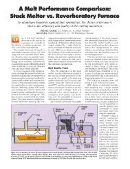
4.1.6 Reverberatory Furnaces<br />
Reverberatory furnaces melt aluminum with the heat that re-radiates from the hot refractory<br />
heated by the burners mounted in the roof or in a sidewall of the furnace, as shown in Exhibit 15.<br />
The molten metal is held inside the furnace at the required temperature before it is tapped out for<br />
pouring or transferred to a holding furnace.<br />
17
Exhibit 15: Reverberatory furnace schematic 33<br />
Gas reverberatory furnaces are commonly used in large nonferrous casting foundries as they<br />
provide a large reservoir of molten metal, ensuring a steady and reliable supply of molten metal<br />
to the shop. For this reason, many large- and medium-sized shops use them as central melters to<br />
supply multiple operations located within the shop. Typical capacity of the furnace can range<br />
widely from 1 to 75,000 tons. The advantages of reverberatory furnaces reside in high-volume<br />
processing rates and low maintenance costs.<br />
There are two types of gas reverberatory furnace based on whether the sows, ingots, and revert<br />
materials are preheated before melting or not. A dry hearth reverberatory charges and preheats<br />
sows, ingots, and revert materials on a slope between the charging door and the molten metal<br />
bath, removing any contamination or water residue prior to melting, preventing splashing or<br />
explosions. A wet bath reverberatory directly dumps the sows, ingots, and reverts into the molten<br />
metal bath. The wet bath system is beneficial for melting scrap types with large surface to<br />
volume ratios, which may oxidize excessively unless melted quickly.<br />
Another type is a side-well reverberatory furnace that consists of a number of burners firing<br />
inside the hearth, against the furnace’s hot wall or door. A charging well and a pump well are<br />
attached to the furnace’s hot wall on the outside of the furnace. Both wells are connected to each<br />
other and with the furnace hearth by arches, which permit aluminum circulation between the<br />
furnace chambers. 34 During the charging period of the furnace cycle, molten aluminum circulates<br />
through the charge well where it melts the scrap, then circulates back into the hearth for<br />
reheating. Charging continues until the molten bath reaches the desired level. Subsequent steps<br />
in the smelting process may include degassing and alloying.<br />
Although the reverberatory furnace has the advantages of large supply of molten metal, it has<br />
low energy efficiency, high oxidation rate, and large floor space requirement. The energy<br />
efficiency of the reverberatory furnaces ranges from 20 to 25%. <strong>Energy</strong> is mainly lost through<br />
the hot flue gases. In addition, as the molten metal comes in contact with the furnace gases, it<br />
forms slag/dross. The melt loss rate is 3 to 5% in aluminum gas reverberatory operations. 35<br />
Improvements in burner technology, fuel/air ratio control, insulating refractories, and<br />
temperature control have contributed to a slow but steady improvement in the efficiency of<br />
18
everberatory furnace. <strong>Energy</strong> benefits from refractories in reverberatory furnace alone could<br />
save up to 78 trillion Btu per year. 36<br />
4.1.7 Rotary Furnaces<br />
Rotary furnaces are an alternative for all small- and mid-sized foundries using cupola furnaces or<br />
induction furnaces. 37 They are more efficient than reverb furnaces, transferring heat via both<br />
radiation and direct contact between the melt and the refractory as the heat passes beneath the<br />
charge (Exhibit 16).<br />
SECO/WARWICK Corporation<br />
Exhibit 16: Rotary furnace<br />
The air/fuel rotary furnaces that were used to melt iron, lead, brass and aluminum have almost<br />
disappeared in the foundry industry because they had low melting rates and were difficult to<br />
control the temperature and quality. However, in the last decade, a new generation of rotary<br />
furnaces has been introduced which are fully automated and include a tilting mechanism for the<br />
furnace. 38 The ability of the furnace to tilt minimizes the amount of time spent on non-melting<br />
operations such as charging, tapping, drossing off and cleaning. As compared to the old type, the<br />
new generation of rotary furnaces uses oxygen to combust the fuel. Higher melting rates, reduced<br />
emissions, consistent metal composition and lower fuel consumption are achieved with this<br />
furnace because the hot refractory rotates to transfer more heat to the charge/bath via direct<br />
contact. (Direct-charging oily scrap can further reduce effective Btu/lb requirements in rotary<br />
furnaces due to the combustion of the evolved hydrocarbons.) Other advantages of the system<br />
are its minimal space requirement, ease of operation, and simplicity to maintain.<br />
A properly designed door and control system enable more efficient furnace operation by<br />
monitoring flue gas emissions, temperature, and furnace rotation parameters. Adding a door and<br />
control system to an oxy-fuel double-pass rotary furnace often increases production by 15%.<br />
Other advantages of a properly designed door include radiation heat loss reduced by almost 1<br />
19
million Btu/hr, better control of free oxygen from elimination of air entrainment, reduced dusting<br />
and noise, and improved fuel efficiency of up to 20%. These benefits can cut processing cost by<br />
a further 10% compared to furnaces without a door. 39<br />
4.1.8 Stack Furnaces<br />
The stack furnaces are receiving more attention in recent years due to their higher energy<br />
efficiency than of the reverberatory furnaces. It can be considered as a modified reverberatory<br />
where its efficiency is improved by better sealing of the furnace and the use of the flue gases to<br />
preheat the charge materials. The charge materials slide down the shaft and reach the melting<br />
zone where they are melted by the burners, and the molten metal flows down to the holding area<br />
(Exhibit 17). The hot exhaust gases from the melting zone flow through the shaft to preheat the<br />
incoming charge, improving the energy efficiency of the stack furnace by 40 to 50%.<br />
Source: Case Western Reserve University<br />
Exhibit 17: Schematic of stack furnace<br />
The disadvantage of the stack furnace is that due to the charging mechanism, the height of the<br />
stack furnace has to be more than 20 feet. 40 In addition, as the furnace is charged from the top of<br />
the shaft, the refractories at the bottom of the charging door are subjected to repeated impact and<br />
wear. This requires additional maintenance. The stack furnace can be coupled with other melting<br />
systems to improve its efficiency. For example, it can be used with a crucible furnace, reducing<br />
its melt losses since the crucible melts by indirect heat to the metal through the wall of the<br />
furnace.<br />
20
4.2 Experimental <strong>Melting</strong> Furnaces<br />
Several innovative melting technologies are being currently experimented world over, each with<br />
its advantages and barriers that are keeping it from wide commercial applicability. Exhibit 18<br />
lists these technologies with their current capacities.<br />
Experimental <strong>Melting</strong> <strong>Technologies</strong> Capacities<br />
Electron Beam <strong>Melting</strong><br />
Immersion Heater (High-Temperature<br />
<strong>Melting</strong>)<br />
100 to 3,000 kW power melting cast ingots of sizes up to 10 ton for<br />
steel, 2-5 ton for titanium, up to 2 ton for zirconium, and 5 ton for<br />
niobium, tantalum and molybdenum 41<br />
70,000 Btu/hr-ft 2 in Isothermal <strong>Melting</strong> Process (ITM); melt rate of<br />
2.5-3.75 tons/hr 42<br />
Infrared Heating Heating at 50-400°C/sec (120-750°F/sec)<br />
Microwave <strong>Melting</strong><br />
<strong>Melting</strong> one to hundreds of pounds of titanium, aluminum, gold, or<br />
silver at a rate of 1 ton/hr (still under development) 43<br />
Plasma Heating <strong>Melting</strong> 4,000 tons per year at 5,100 kWh 44<br />
Solar Furnace<br />
<strong>Melting</strong> temperature up to 33,000°C (60,000°F) and producing over<br />
1,000 kWh of energy<br />
Exhibit 18: Experimental melting technologies and their capacities<br />
4.2.1 Electron Beam <strong>Melting</strong> (EBM)<br />
EBM furnaces melt the metal by focusing a beam of electrons from an electron gun on the metal.<br />
When the electrons strike the material, their energy is absorbed in quantities sufficient to melt the<br />
metal. EBM method was first introduced in 1907 to melt high-melting-point metals, such as<br />
tantalum and tungsten. It was not until recently that electron beam was recognized for its<br />
application in metal-purifying processes. This is the principal technology for processing of<br />
reactive metal scrap. EB technology is also the only technology that makes it possible to monitor<br />
the cleanliness of metals using specially designed button melters.<br />
There are two processes used today: drip melting and<br />
electron beam cold-hearth refining (EBCHR). Drip<br />
melting melts the metal in a water-cooled ingot mold<br />
enabling removal of entrapped gases and evaporation of<br />
all impurities as their vapor pressures exceed that of the<br />
metal being processed. In EBCHR, the molten metal<br />
flows along a water-cooled hearth before entering a<br />
water-cooled ingot (Exhibit 19). While flowing along<br />
the hearth, high- and low-density inclusions are<br />
removed in addition to evaporative purification. Highdensity<br />
inclusions settle and are removed in the scull,<br />
while lighter inclusions either are dissolved in the metal<br />
or held back by a dam prior to flowing into the ingot.<br />
21<br />
Source: http://www.timet.com/naops/vebchrmelt.html<br />
Exhibit 19: Electron Beam Cold-<br />
Hearth Refining
EBM is distinguished by its refining capacity. However, electron beam technology is primarily<br />
for melting refractory metals and laboratory-scale melts. One of the disadvantages of the electron<br />
beam process is its high capital cost due to its requirement of vacuum pumps. In addition, the fit<br />
up must be precise and locating the parts with respect to the beam must be perfect. 45 Therefore,<br />
the technology is not applicable in typical foundry operations.<br />
4.2.2 Immersion Heaters (High-Temperature <strong>Melting</strong>)<br />
Immersion heaters, although well established for melting zinc, is currently not well-adapted for<br />
melting metals with higher melting points. The protective ceramic coatings pose thermal barrier,<br />
lowering the melting efficiency. Several <strong>ITP</strong> <strong>Metal</strong> <strong>Casting</strong> projects are currently focusing on<br />
enabling this technology commercially.<br />
One <strong>ITP</strong>-sponsored project addresses the critical need for advanced materials that are lighter,<br />
stronger, and more corrosion-resistant than metals. 46 Work has been done to optimize the nitridebonded,<br />
silicon-carbide-fiber-reinforced Continuous Fiber Ceramic Composite (CFCC)<br />
immersion tube burners for application in aluminum and other light metal melting. The project<br />
validated that CFCC materials are stable in molten aluminum and in combustion gas for long<br />
periods. When tested at an industrial site, the immersion tube survived over 1,000 hours and 31<br />
cycles in an aluminum casting furnace. In another testing, the immersion tube successfully<br />
survived for 1,752 hours in the furnace.<br />
<strong>ITP</strong> has also been supporting research effort in the development of intermetallic alloys that<br />
possess improved or unique environmental resistance, which can result in efficiency benefits and<br />
energy savings. 47 Recently, researchers developed Ni3Al alloy that can withstand service<br />
temperatures of 100 to 150°C (180-270°F) higher than commercial Ni3Al alloys. Other alloys<br />
under study are based on the intermetallic alloy FeAl. These alloys can resist carburization and<br />
sulfidation that most commercial alloys cannot. In addition, alloys based on Ni3Si are being<br />
developed. The Ni3Si alloys have good mechanical properties and excellent resistance to<br />
oxidizing conditions, such as in sulfuric acid and seawater, and to ammonia at temperatures up to<br />
900°C (1,650°F). These kinds of intermetallic alloys can be applied in immersion heater tubes to<br />
withstand any wear from chemical reactions.<br />
An <strong>ITP</strong> cost-shared project called “Isothermal <strong>Melting</strong> (ITM)” shows promise for developing<br />
future models with in-plant thermal efficiencies of 97%. New materials and construction<br />
techniques allow immersion heaters to be built with high heat flux (approximately 70,000 Btu/hrft<br />
2 ) and external coatings that provide mechanical and chemical protection. These new heater<br />
designs are based on a highly conductive, impact- resistant ceramic coating on a metallic sheath<br />
and a highly thermally conductive, dielectric integral coupling medium between the sheath and<br />
the heat-producing element. This allows heat transfer by conduction to be the dominant mode,<br />
rather than particle-to-particle radiation heat transfer that prevails in conventional electric<br />
immersion heaters with compacted powder coupling media. The composite refractory coating is<br />
resistant to corrosive attack by the molten aluminum, yet sufficiently thin enough to provide a<br />
high heat flux. High flux heaters incorporated into the ITM are practical for large-scale<br />
applications. 48<br />
22
Another project sponsored by the <strong>ITP</strong> <strong>Metal</strong> <strong>Casting</strong> is developing integrated retrofit<br />
technologies for clean aluminum melting systems by focusing on immersion heating coupled<br />
with metal circulation systems. 49 This is being achieved through substitution of conventional<br />
radiant burner method with immersion heating in reverberatory furnaces. The program will<br />
enable cost-effective retrofits to a range of existing furnace sizes, reducing economic barrier to<br />
implementing new applications.<br />
4.2.3 Infrared Heating<br />
Infrared heating is currently being employed by the forging industry; this technology can also be<br />
used for die heating and heat treatment in the metal casting industry. It offers a method for<br />
reducing time and energy costs of die preheating. A study conducted by ORNL indicated that the<br />
surface of the die can be heated to 300°C (572°F) in less than 20 minutes. 50 An infrared panel<br />
heater can bring the furnace to full power in a matter of seconds, saving energy to maintain a hot<br />
furnace while idle (Exhibit 20). 51 The rapid heating could also reduce heat-treatment cycle time<br />
and increase product throughput.<br />
Infrared radiation is often supplied by high-intensity quartz heat lamps, producing radiation of<br />
around 1 micron wavelength. This radiation melts metals with uniform heat distribution. The<br />
high-density infrared technology can achieve a heating rate of 50 to 400°C/sec (120 to<br />
750°F/sec). 52<br />
Source: Oak Ridge National Laboratory<br />
Exhibit 20: Electric infrared flatbed furnace<br />
(used for both laboratory and industrial testing)<br />
Recently, DOE funded a study on surface treatments on refractories used in aluminum<br />
processing. 53 High-density infrared processing will be used to apply corrosion-resistant, high<br />
emissivity coatings on refractories so as to reduce its porosity.<br />
23
4.2.4 Microwave <strong>Melting</strong><br />
Originally developed by the DOE’s Y-12 National Security Complex for melting of uranium,<br />
microwave technology is now capable of melting a wide range of alloys in large quantities. 54<br />
While conventional heating involves transferring of heat through the outer surface of the material<br />
to the interior, microwaves can penetrate the mass, enabling rapid transfer of high-intensity heat<br />
throughout the bulk. This translates into significant savings in time and energy.<br />
Three basic elements are required to heat and<br />
melt bulk metals using microwaves: a<br />
multimode microwave cavity, a microwaveabsorbing<br />
ceramic crucible, and a thermally<br />
insulating casket that is microwave-transparent.<br />
Although metal is supposed to reflect<br />
microwaves, researchers at Y-12 and<br />
Pennsylvania State University found that metal<br />
actually starts to absorb the energy and heat at<br />
three-fourths of the melting temperature.<br />
Source: Y-12 National Security Complex<br />
Exhibit 21: Suscepting crucible<br />
55 A<br />
uniquely designed suscepting crucible used for<br />
microwave melting is shown in Exhibit 21. 56<br />
The metal charge is placed in an open (no lid)<br />
ceramic crucible, and the insulating casket is<br />
positioned to cover the open crucible<br />
completely. The heated crucible walls quickly<br />
heat the metal charged in the crucible by means<br />
of radiation, conduction, and convection. The<br />
thermally insulating casket increases the energy<br />
efficiency of the microwave system by trapping<br />
the heat generated in the crucible. According to a Y-12 publication, microwave melting could cut<br />
melting cost by 30%. Germany and Japan are taking a strong lead in the microwave technology<br />
applications in high-temperature processes and microwave-assisted kilns/furnaces.<br />
Some of the current focus areas in microwave melting technology include use of microwaves for<br />
roasting ores, heat-treating glass, detoxifying filter dusts and slag in the metal industry, and<br />
decontaminating asbestos containing wastes. 57 In addition, research is being conducted by<br />
Michigan Technological University using a combination of microwave, electric arc and<br />
exothermic reactions to heat and smelt iron. 58 Since iron ore and carbon are excellent microwave<br />
absorbers, microwave technologies can aid more effective melting in electric arc furnaces used in<br />
steel foundries.<br />
However, bulk metals do not readily couple directly with microwave energy at room temperature<br />
because they are electrically conductive, readily reflecting the incident energy. 59 In addition,<br />
microwave melting requires 2.35 micron radiation which is very expensive. This limits the use of<br />
microwave melting to high-end processes and alloys such as investment casting and super alloys.<br />
24
4.2.5 Plasma Heating<br />
Exhibit 22: Plasma heating<br />
Plasmas are gaseous collections of electrically<br />
charged particles such as electrons and protons.<br />
These charged particles carry energy; as the ionized<br />
plasma flow hits the metal surface, it releases its<br />
energy melting the metal.<br />
The plasma melting process is proved to be more<br />
energy efficient than the conventional melting<br />
technologies as it can raise the temperature very<br />
rapidly (Exhibit 22). Plasma aluminum melting<br />
furnaces are reported to impart heat 60% quicker<br />
than the conventional high rate melters. Due to the<br />
fast heat transfer, the melting process is also rapid.<br />
The energy consumption rate is as low as<br />
0.198 kWh/lb (of aluminum) compared to 0.345<br />
kWh/lb (of aluminum) in induction melting. 60<br />
The plasma melting process also minimizes metal loss due to oxidation and contamination. The<br />
plasma keeps a thin oxide film on molten metal intact, protecting the molten metal from<br />
absorbing gases. In fact, the dross rate of melting aluminum is lowered to less than 1% compared<br />
to the conventional 3 to 12%. 61 Plasma heating also reduces the cost of fuel. A recent<br />
development of plasma heating utilizes ambient air and converts it to nitrogen, eliminating the<br />
need to purchase expensive gases such as nitrogen or argon required in conventional plasma<br />
heating.<br />
4.2.6 Solar Furnaces<br />
Solar furnaces use large arrays of mirrors to concentrate<br />
the sun's energy into a small space and produce high<br />
heat flux and very high temperatures (Exhibit 23). They<br />
can achieve temperatures up to 33,000°C (60,000°F)<br />
and produce over 1,000 kWh of energy. Solar furnace<br />
system consists of a solar concentrator, featuring<br />
advanced structural mirrors, and system controls, which<br />
provide fully automated operation, fault detection,<br />
data<br />
acquisition, and communications. The sun-tracking<br />
mirrors concentrate sunlight onto a receiver that sits on<br />
top of a platform extended about 18 feet from the wall<br />
mirrors. The receiver collects and transfers the sun’ s<br />
heat to experimental equipment.<br />
One<br />
aspect of the solar system that makes it appealing<br />
for electricity production at remote sites is its ability to<br />
operate automatically. Without operator intervention or<br />
even onsite human presence, it starts up each morning<br />
25<br />
Source: The Institute for Material Science and<br />
Process Engineering (IMP)<br />
Exhibit 23: Solar furnace
at dawn and operates throughout the day, responding to clouds and wind as needed. Finally, it<br />
shuts itself down at sunset. The system can be monitored and controlled over the Internet. 62<br />
Although solar furnaces are the ideal metal melting systems in terms of energy efficiency, they<br />
are very capital intensive and operate only under a sunny sky. These furnaces also require acres<br />
of land to place the reflective mirrors. Because of these restrictions, solar furnace is used mainly<br />
for scientific experiments, lacking the practicality to be applicable immediately in typical<br />
foundry operations.<br />
4.3 Heat Recovery Methods<br />
Much of the heat produced in melting operation is lost to atmosphere. When this waste energy is<br />
re-used, it may save up to approximately 20%<br />
,<br />
such<br />
63 of a facility’s energy cost and, in some cases,<br />
reduce emissions. Waste-heat-recovery devices (recuperators, regenerators, shaft/stack melters<br />
etc.) simply transfer thermal energy from the high-temperature effluent stream to a lowertemperature<br />
input stream (make-up air or metal charge). Waste-heat-conversion methods,<br />
as absorption refrigeration, thermoelectrics and thermionics, utilize the elevated flue gas<br />
temperatures to drive energy conversion devices.<br />
4.3.1 Recuperators<br />
A recuperator is a gas-to-gas heat exchanger<br />
placed on the stack of the furnace (Exhibit 24).<br />
Heat recuperators recover heat from the exhaust<br />
gases and heat the incoming combustion air.<br />
l rely<br />
streams<br />
ble<br />
orrosive<br />
64<br />
Recuperators are available in many sizes,<br />
configurations, and temperature ranges. Al<br />
on tubes or plates to transfer heat from the<br />
outgoing exhaust gas to the incoming<br />
combustion air, while keeping the two<br />
from mixing. 65 Due to the continuous hightemperature<br />
process, recuperators must be<br />
protected against heat and may not be suita<br />
for unclean, corrosive exhaust gases. Chlorine<br />
gas is frequently used to purify molten<br />
aluminum and its byproducts are very c<br />
to a recuperator’s materials.<br />
Exhibit 24: Schematic of a heat recuperator 66<br />
One of the most common recuperators is a metallic radiation recuperator, which consists of two<br />
concentric lengths of metal tubes. The inner tube carries hot exhaust gases that radiate heat to the<br />
inner wall of the recuperator, and the external tube carries the cooler gas to be heated.<br />
A convective recuperator is another type of recuperator that circulates hot gases through several<br />
small-diameter pipes contained within a larger shell. The cooler gases pass over the pipes and<br />
absorb much of their heat.<br />
26
A vertical tube-within-tube convective recuperator is an alternative arrangement of the<br />
convective recuperator where the cold combustion air is heated in a tank of parallel vertical tubes<br />
extending<br />
in to the path of flue gas stream. The tube is easy to replace during full operation,<br />
minimizing cost, inconvenience, and equipment damage from forced shutdowns in case of<br />
recuperator failures. 67<br />
4.3.2 Refrigeration<br />
Absorption chillers use heat instead of mechanical energy to provide cooling for applications<br />
such as air conditioning.<br />
They transfer their thermal energy from the heat source to the heat sink<br />
through an absorbent fluid and a refrigerant. The two most common refrigerant/absorbent<br />
mixtures used in absorption chillers are water/lithium bromide and ammonia/water. The<br />
absorption chiller creates refrigerating effect by absorbing and then releasing water vapor into<br />
and out of a refrigerant solution (Exhibit 25). 68<br />
Source: Gulf Coast CHP Application Center<br />
Exhibit 25: Simplified absorption cycle<br />
Absorption chillers are economically attractive because they utilize<br />
inexpensive thermal energy<br />
(waste heat). Mechanical chillers must be driven by motor or engine; however,<br />
absorption<br />
chillers primarily use low-grade waste heat at a temperature between 100°C and 200°C (212°F<br />
and 392°F). These chillers can change a building’s thermal and electric energy and cost profile<br />
by shifting cooling needs from an electric load to a waste-heat thermal load.<br />
4.3.3 Regenerators<br />
A regenerator is a container that is capable of absorbing and storing large amount of thermal<br />
energy. It is charged with<br />
the hot exhaust gas during the melting operation cycle; when the<br />
regenerator is fully charged, it stops the flow of the exhaust gas and starts allowing in<br />
27
combustion air to pass through the regenerator. The combustion air then enters the furnace with<br />
increased temperature.<br />
A continuous heat recovery operation requires at least two regenerators – one that provides<br />
energy to the combustion air, while the other recharges from the flue gases (Exhibit 26). An<br />
alternative<br />
arrangement involves a continuously rotating wheel where flue gas and the<br />
combustion gas flow through different parts of the wheel as it rotates allowing for heat transfer.<br />
Source: http://www.eere.energy.gov/industry/bestpractices/pdfs/35876.pdf<br />
Exhibit 26: Schematic of a regenerator system<br />
While recuperators separate the gas streams with physical barriers for a continuous<br />
operation,<br />
regenerators separate gas streams by time lag and operate intermittently. he switching of gas<br />
stream back and forth requires more complex, expensive control system than recuperators.<br />
69 T<br />
4.3.4 Thermoelectric Devices<br />
Thermoelectric, thermionic, and IR-photovoltaic materials use temperature gradients to produce<br />
electricity. Their conversion efficiencies<br />
today are low (typically
molten metal between furnaces or to the casting station is a critical step in the casting process<br />
that could be improved for energy efficiency. With the rising gas and electric prices, maintaining<br />
the temperature of the metal between the melting furnace and the pouring station can be<br />
expensive. If the distance between the melting room and pouring room is short or negligible,<br />
70<br />
then less heat would be needed to do so. Thus, close proximity of the furnace to the pouring<br />
location can add up to substantial annual savings and improved safety.<br />
4.4.1 Dosing Furnaces<br />
Dosing furnaces are closed holding furnaces with a<br />
spout for direct metal delivery (Exhibit 27). They are<br />
used to dispense an accurate amount of molten metal<br />
to<br />
the die casting machine or mold line. The advantage of<br />
the dosing furnace is that because of the closed<br />
structure, it minimizes heat loss and protects the molten<br />
metal from excessive oxidation. These furnaces require<br />
only about one-fifth of the energy to hold 2,000 pounds<br />
of aluminum in comparison to an open crucible furnace,<br />
and one-third of the operating costs of a comparable<br />
holding furnace. In Europe, dosing furnaces are<br />
replacing ladle furnaces in die casting because of their<br />
ability to pour accurate amount of molten metal at<br />
the<br />
right temperature. 71<br />
4.4.2 Electro-Magnetic<br />
Pump Systems<br />
Source: Case Western Reserve University<br />
Exhibit 27: Schematic of dosing<br />
furnace<br />
An electromagnetic pump (EMP) may be used to<br />
circulate hot metal through a patented scrap charging<br />
chamber (Exhibit 28).<br />
g of<br />
72 The pump circulates the<br />
molten bath in the reverberatory furnace at a maximum<br />
flow rate of approximately 10 tons/minute. Meltin<br />
metal inside wells, supplied with molten metal from<br />
electro-magnetic pumps, has become more common<br />
since the mid-1990s.<br />
EMP systems offer two opportunities to improve<br />
melting<br />
efficiency: temperature homogeneity of the<br />
melt pool and side-well melting. The melt pool in most<br />
furnaces is stagnant, which contributes to the<br />
http://www.sovereign-publications.com/emp.htm development of a vertical temperature profile in the<br />
Exhibit 28: Electro-magnetic pump<br />
pool. When the surface temperature of the molten<br />
system<br />
metal is different from the floor temperature, it creates<br />
inefficiency since radiant energy from the roof and conductive energy from the hot flue gases is<br />
being directed at the hot side of the metal pool. Stirring of the pool with electro-magnetic pumps<br />
can eliminate the vertical temperature profile, enhancing efficiency and productivity. Also EMP<br />
29
systems can be used in combination with a reverberatory furnace where hot metal is circulated<br />
by means of a high-capacity pump from the hearth to a special charging well, then back into the<br />
hearth, either directly or through a dross-settling well.<br />
EMP systems can be adapted and retrofitted to varied furnace configurations, including closed<br />
hearth,<br />
twin chamber, open-well, and tilting furnaces. The pump itself has no moving parts and<br />
requires limited preventive maintenance. High recovery rates are also achievable without the use<br />
of salts.<br />
4.4.3 Ladles<br />
Ladles are also used to transfer molten metal from a holding furnace to the pouring station or<br />
shot sleeve of a die cast machine. The automation of the ladle system allows the delivery of<br />
molten metal in a consistent period for every cycle with accurate quantity of molten metal. The<br />
use of auto ladling equipment has become commonplace in aluminum die casting, resulting in<br />
less pouring-related casting defects and low burden on the manpower used in hand pouring.<br />
es<br />
n<br />
73<br />
Effective insulation of the ladle allows more efficient transfer of the molten metal. This increas<br />
ladle capacity and reduces largely operating costs. Other benefits include the ability to maintai<br />
the current lining profile, minimize heat loss, and reduce energy consumption. 74<br />
Preheated ladles can also reduce the melting energy required in the furnace (higher<br />
tap<br />
temperatures<br />
are required). Plants driven by productivity (tapping as many heats as possible<br />
every shift) typically tap into ladles that are fully soaked and preheated. On the other hand,<br />
plants<br />
that are limited in productivity by schedule (limited number of heats per shift) typically have<br />
ladles that are not completely soaked. At this time, most ladle metallurgy consists of wire<br />
feeding with limited use of gas stirring or metal heating.<br />
4.4.4 Launder Systems<br />
Improvements in launder system<br />
allow uninterrupted flow of molten metal from furnace to the<br />
pouring station/die casting machines. This improved system eliminates time and labor expenses.<br />
The launder is insulated well to conserve energy as the molten metal travels from the central<br />
furnace to another location. The use of a central melting furnace with a fully covered design of<br />
the launder substantially reduces metal loss due to oxidation and eliminates the hazards of<br />
exposed molten metal and radiant heat to the work area. In aluminum launder systems, effective<br />
insulation helps maintain the temperature of the molten material at approximately 750 ○ C<br />
(1,400 ○ F) to avoid “freezing” the molten aluminum and to maintain consistent flow throughout<br />
the distribution system. The recent development in insulation technology can reduce the<br />
insulation thickness by 1.5 inches, reduce cold face temperatures by 43%, and reduce heat loss<br />
by up to 67%. It also improves product quality and extends launder life.<br />
30
4.4.5<br />
Mechanical Circulating Pumps<br />
Lack of effective circulation in the molten metal in the<br />
furnace tends to concentrate the heat on the surface of the<br />
molten bath and also, increase surface oxidation and dross<br />
formation. Temperature differences within the bath can be<br />
as high as 60 to 100°C without effective circulation,<br />
l<br />
75<br />
while good circulation can reduce it to as low as 4°C. The<br />
mechanical pump (Exhibit 29) forces the circulation of the<br />
molten metal bath, reducing convective energy loss from<br />
the surface of the bath. Benefits of homogeneous<br />
temperature include improved melting rate, reduced melt<br />
cycle time, enhanced metal quality, and reduced energy<br />
consumption. In addition, the stirring of molten bath<br />
increases refractory life as more heat is transferred to the<br />
metal and less is absorbed into refractories. Traditional<br />
pump systems have graphite posts that are vulnerable to<br />
oxidation and, therefore, require frequent replacements. A<br />
recent technology replaces graphite with stronger materia<br />
such as ceramic and steel. 76<br />
4.5 Fuel Combustion <strong>Technologies</strong>: Oxy-Fuel Burners<br />
Source: Metaullics Systems<br />
Exhibit 29: Mechanical<br />
Circulating Pump<br />
Alternative combustion technologies, especially oxy-fuel burners, have been attracting<br />
significant attention because of the increasing environmental demands for reduced emissions,<br />
particularly of NOx and improved energy efficiency in remelt furnaces. The use of oxy-fuel<br />
burners increases the chemical energy and decreases the electrical energy.<br />
Increased oxygen in the furnace environment, however, can lead to greater oxidation of the melt<br />
surface and increased dross formation. These effects translate into reduced thermal<br />
transfer to the<br />
melt and increased melt loss. Further, some foundries are hesitant to implement oxy-fuel burners<br />
because they are afraid of wearing the refractories at a greater rate. Balancing these apparently<br />
competing effects has been the focus in designing combustion approaches to ideally obtain low<br />
NOx emissions and minimal melt loss.<br />
<strong>ITP</strong>-sponsored research has been conducted on minimizing NOx emission using oxygenenhanced<br />
combustion. nd that the thermal performance of a burner was<br />
y half<br />
a<br />
77 Researchers fou<br />
optimized by enriching the flame within a range of 35 to 50% oxygen, consuming roughl<br />
of the oxygen of traditional oxy-fuel system. Use of a novel air-oxy-natural-gas burner at<br />
commercial furnace at Wabash Alloys plant in East Syracuse, New York has demonstrated 30%<br />
increase in productivity, 40% increase in energy efficiency, as well as substantial reduction in<br />
NOx emission.<br />
of burner efficiency and dross formation on aluminum melt. 78 A project led by the Gas Technology Institute (GTI) and sponsored by <strong>ITP</strong> addressed the<br />
combined issues<br />
The work focused<br />
on<br />
air-oxy-fuel mixture burners, with the optimum oxygen range of 30 to 35%; the project is<br />
31
developing burners that allow specific control of flame shape and oxygen distribution within<br />
the<br />
flame. Using the concept of “self-optimized combustion system,” a flame was produced that has<br />
a fuel-rich zone at the bottom to minimize exposure of the aluminum surface to oxygen.<br />
Innovative burners can also contribute to the reduction of melt loss. Studies in formation of<br />
oxides and spinals, turbulence, and alloy constituents can reduce melt loss. Secat, Inc. is<br />
currently<br />
leading quantitative research on formation mechanisms and potential alternative<br />
solutions. ce<br />
79 Possible solutions identified in the early stages of the project are control of furna<br />
atmosphere, use of minor alloying elements that dramatically affect the kinetics of oxide<br />
formation, and reduced melt surface/furnace atmosphere interface through various barrier<br />
techniques. The project aims to reduce melt loss by 2%.<br />
4.6 Preheating Systems<br />
The high-temperature off-gas from the melting furnace can be used to preheat scrap for the<br />
second charge of the heat or the first<br />
charge of the next heat. Scrap preheating has proven to<br />
reduce the energy for melting (by up to 50-75 kWh per ton).<br />
The off-gas, which normally exits through the “fourth hole,” preheats the scrap to a temperature<br />
in the range of 450°C to 600°C (840°F to 1,110°F). A side benefit<br />
of preheating is complete<br />
removal<br />
of moisture from the scrap. Preheating the scrap to an average temperature of 500°C<br />
(930°F) reduces the electrical energy requirements by 30 to 60 kWh per ton and power-on time<br />
by 5 to15%. However, in some cases, the delays associated with scrap preheating can reduce<br />
productivity. Some specific technologies are reviewed below.<br />
4.6.1 Shaft Furnace<br />
A shaft furnace is an advanced form of scrap preheating. It is mounted on top of the electric arc<br />
furnace; off-gases leaving<br />
the melt zone rise up the shaft and pass through the next scrap charge.<br />
A number of shaft furnaces are in operation in the steel industry in the United States, Mexico,<br />
and Europe. It is reported that up to180 kWh/ton energy savings can be achieved with a twin<br />
shaft and 135 kWh/ton with a single shaft. Types of shaft furnaces include Comelt,<br />
a<br />
a<br />
80 a furnace<br />
designed with inclined electrodes and a shaft furnace feeding the scrap between the electrodes;<br />
single electrode DC furnace with scrap preheating and extensive use of burners; and Conarc, 81<br />
basic oxygen furnace and electric arc furnace using extensive decarburization of hot metal.<br />
In order for the shaft furnace to be practical, the heat size must be at least 45 tons and the furnace<br />
must be equipped with gas burners to generate sufficient off-gas. The complexity of these<br />
technologies<br />
requires large capacity furnaces operated on a continuous basis to be technically<br />
and economically feasible. Therefore, these technologies are not applicable to typical foundry<br />
operations.<br />
The Japanese steel industry is developing the Econarc process, which uses extensive methane<br />
82<br />
and shaft furnace<br />
preheating. They have operated a 130-ton furnace. However, because the<br />
32
scrap preheating system must be of large capacity to capture the energy from combustion, this<br />
system is also impractical for foundry operations.<br />
4.6.2 Twin Shell System<br />
Preheating systems have been in use for more than a decade in electric arc furnace steel melting<br />
shops. Twin-shell furnaces are among the more recent developments, incorporating preheating as<br />
an integral part of the melting process. At a twin-shell operation, while one part of the furnace is<br />
making steel, the other side is being loaded with scrap. The off-gas from the operating side of the<br />
two-furnace system is piped to the other side to heat the charge before melting. Generally, this<br />
technology is used with a single graphite electrode DC furnace.<br />
The off-gas from the current heat being melted or refined is passed through the scrap for the next<br />
heat in the second furnace shell. Typically, only the first charge is preheated. Therefore, most<br />
plants try to operate with a single charge. Twin shell systems are cheaper than having two<br />
separate electric arc furnaces because they require only one set of electrodes and achieve similar<br />
production rate. Electricity costs are also lower with the twin shell system. When two scrap<br />
charges are required, the first (preheated charge) contains approximately 60% more scrap than<br />
the second charge. Preheating in the second shell can also be supplemented by gas burners.<br />
Nippon Steel reported energy consumption of 260 kWh/ton steel with preheating to about 900°C<br />
(1,650°F), achieving a 30% energy reduction from conventional melting. This technology is<br />
applicable to larger foundries’ arc furnaces (greater than 20 ton) but would be difficult to retrofit<br />
as it requires replacement of furnaces.<br />
4.7 Refractories<br />
Refractories are used throughout the various processes conducted in all kinds of furnaces in the<br />
metal casting industry, affecting approximately 90% of the direct energy consumption in these<br />
processes. Improvements in refractory systems, such as life extension, offer high potential to<br />
save energy up to 8.5 trillion Btu per year.<br />
g<br />
t<br />
83 Ceramic linings are used in most furnaces to<br />
minimize reaction resulting in corrosion or mechanical damage in the furnace when processin<br />
specific metals. Although the service life of refractory linings has been extended in the las<br />
decade, there still exists a substantial problem where thermal efficiency may be sacrificed for a<br />
better protective refractory lining.<br />
A recent development in insulating materials is the use of micro-porous silica. The improved<br />
opacifiers<br />
block heat transfer in radiation lowering thermal conductivity. The low thermal<br />
conductivity can increase the capacity of ladles, kilns, industrial ovens and commercial<br />
appliances while maintaining or improving thermal performance. It can reduce weight, which<br />
in<br />
turn, can reduce structural requirements for furnaces and other high-temperature vessels.<br />
The development of insulation system within refractory system also ensures proper temperature<br />
control<br />
in melting systems (for example, maintaining a homogeneous aluminum liquid<br />
throughout the aluminum melter). The board form of the new insulation materials can backup<br />
33
insulation to reduce heat loss, improve product quality, and reduce operation costs. In addition, it<br />
can reduce insulation thickness by 50% compared to ceramic fiberboards and minimize heat loss<br />
by 30%. It also improves product quality and extends furnace life.<br />
However, barriers still exist. Research is required to develop methods to reduce/eliminate<br />
refractory failure due to physical erosion and chemical corrosion (by MnO and FeO in steel<br />
foundries),<br />
fusion of refractories, clogging or build-up formation in channels and throats, highly<br />
basic (calcia-containing) slags in steel casting, and other factors. Reducing the thermal<br />
conductivity, as well as improving the chemical and mechanical properties of the refractories,<br />
will have a significant payoff in the overall fuel efficiency of melting operations. 84<br />
4.8 <strong>Melting</strong> Schedule<br />
Even the most efficient furnace could be inefficient with poor scheduling. <strong>Melting</strong> in cold<br />
equirement by as much as 30 to 50% 85 furnaces increases the energy r<br />
from that used by melting<br />
in a hot furnace with a heel. Unlike induction furnaces where a heel reduces energy efficiency,<br />
electric arc furnaces increase efficiency when melting with a liquid heel. The most efficient<br />
operations use creative scheduling (fewer melting days per week, fewer furnaces, etc.) to<br />
maximize the number of heats each day per furnace. Schedules that minimize melting delays<br />
achieve lower energy loss from conduction to the refractory and from liquid surface radiation.<br />
In<br />
addition, energy efficiency is maximized when consistent heat size is scheduled. Scheduling<br />
different-sized heats in the same furnace reduces energy efficiency.<br />
5.<br />
Challenges to Adopting New <strong>Technologies</strong><br />
The adoption of new advanced melting methods in foundries faces several more challenges<br />
besides the specific technical barriers described for the various current and emergent melting<br />
technologies<br />
in section 4. The industry make-up, domestic business climate and strong global<br />
competition in the metal casting sector discourage the implementation of energy-efficient<br />
melting technologies.<br />
Dominance of Small Businesses<br />
industry is dominated by small- to mid-sized companies. Approximately<br />
es have fewer than 100 employees, 14% have between 100<br />
and 250 employees, and the remaining 6% have more than 250 employees. 86 The U.S. metal casting<br />
80% of the 2,480 metal casting faciliti<br />
Small businesses<br />
find it difficult to assume the high costs (labor and facilities) and the risk associated with R&D,<br />
particularly long-term R&D, to improve metal casting technology and process efficiencies.<br />
Moreover, many companies in the industry are hesitant to adopt new technologies, practices, and<br />
tools for fear of possible negative effects that these changes might bring to long-"proven"<br />
production techniques and, as a result, their already small profit margins.<br />
34
Limited Available Resources<br />
comparison of surveys conducted in 2001 and 2003 indicate a significant decline in the profit<br />
margin for an average metal caster from 4.6 to 1.81% of sales, with iron operations specifically<br />
this period. 87 A<br />
losing an average of 1.69% during<br />
The diminishing of the metal casters’ already<br />
small profit margins over the last few years has made it difficult for the industry to invest in<br />
R&D and implement capital-intensive advanced melting technologies.<br />
The metal casting industry prefers to spend its limited resources on incremental improvements<br />
and retrofit technologies to the existing equipment, since they require lower capital investments.<br />
Additionally,<br />
the metal casters, when considering implementing a new or<br />
modified technology,<br />
tend to look at the contribution that the technology can make to their business’s bottom line<br />
rather than its energy efficiency. Many times, metal casters spend significant portions of their<br />
limited resources on new molding technologies and finishing lines in lieu of new melting<br />
systems to improve their casting yield and reduce scrap rates.<br />
Lack of Economies-of-Scale<br />
<strong>Energy</strong> efficiency is related to the size of the melting system. The<br />
smaller equipment size<br />
requirements for the metal casting industry contribute to a higher melting equipment surface area<br />
to volume ratio. This means that the<br />
surface radiation and conduction from the melting devices in<br />
the numerous small casting operations are proportionally greater when compared to the larger<br />
melting devices used for wrought steel and aluminum ingot industries.<br />
The small capacity of furnaces in the majority of the metal casting facilities restricts application<br />
of wrought steel technologies. The small furnaces typically lack an adequate electrical control<br />
system<br />
and computer control of the furnace or additives system to support<br />
the superior<br />
technologies available to the wrought steel and primary metals industries. <strong>Technologies</strong> from<br />
larger metal industries also require an investment in new emission control systems to deal with<br />
the additional off-gas content. This is an added cost for the metal casters, which further<br />
discourages implementation.<br />
Considering a specific case, the majority of the steel foundries are small operations with average<br />
furnace capacity of 13 tons in electric arc furnace shops and a little over 1 ton in induction<br />
furnace<br />
shops, while the furnaces<br />
in the wrought industry can range from 100 to 300 tons. The<br />
markedly smaller scale of the steel furnaces leads to higher heat losses and increased difficulty in<br />
implementation of wrought-type technologies in steel foundries. The long arc and foamy slag<br />
technologies that have been effective in reducing energy consumption in the wrought industry<br />
are not practical for the steel foundries because steel foundry transformers are typically<br />
undersized to accommodate these technologies.<br />
Wide Variation in <strong>Melting</strong> Operations’ Needs<br />
Current melting technologies within the metal casting<br />
industry do not provide for a one-size-fitsall<br />
method because of the immense diversity of the metal casting line of products. Each casting<br />
facility has varying alloying requirements, which influence<br />
the type of melting technologies it<br />
uses. Some furnaces are used to reduce the amount of oxidation of the molten alloys and dross<br />
formation, while others are used because their fuel/feedstock provides the alloying ingredients<br />
35
necessary to impart the mechanical properties the casting facility desires. Furthermore, the<br />
temperature requirements vary for each alloy/metal melted in the furnace. Therefore, the concept<br />
of a single melting technology that can crosscut the entire metal casting industry is unreasonable.<br />
Advances along multiple pathways are required that suit the needs of different casting facilities<br />
for achieving significant energy savings in the overall melting process.<br />
Batch-<strong>Melting</strong> Schedule<br />
The scheduling of melting is traditionally determined by the casting requirements of the metal<br />
casting facility. Most casting facilities melt in batches, in which case, the facilities tend to<br />
schedule to melt at certain hours of the day on certain days of the week. This practice requires<br />
frequent starting and idling of<br />
the melting equipment, thus reducing the efficiency of the<br />
operation. In addition, many metal casters produce variable-sized heats, which require the<br />
operation of several different-sized furnaces and involve heating many cold furnaces, a factor<br />
that further reduces the energy efficiency of melting. The inconsistent heat sizes also increase<br />
the<br />
maintenance cost because of the stress imposed on the furnace refractory from the significant<br />
swings in the temperature.<br />
Requirement of New Permits<br />
New furnace technologies, particularly those that require new or expanded exhaust systems,<br />
frequently require local and state permits. Obtaining these permits incur financial costs and<br />
require valuable personnel time.<br />
Many small metal casters find it difficult to allocate these<br />
resources for acquiring permits when<br />
implementing new technologies at their foundries.<br />
<strong>Advanced</strong> melting technologies that can be retrofitted onto the existing equipment without any<br />
need for new permits are, as a result, more likely to be adopted by the industry.<br />
6. Future Direction of Research: Potential <strong>Energy</strong>-<strong>Saving</strong><br />
<strong>Technologies</strong><br />
The following recommendations for R&D offer the most promising opportunities for decreasing<br />
energy consumption in melting operations in the metal casting industry.<br />
Retrofit <strong>Technologies</strong> Database<br />
Tool<br />
Considering the diversity of the U.S. metal casting operations and their limited resources,<br />
possibly the most advantageous path for introducing energy-efficient melting technologies is to<br />
develop a web-based database tool of available retrofit technologies. This tool will enable metal<br />
casters to compare and weigh their options when evaluating the new melting technologies. The<br />
casters must be able to input their furnace type, scheduling, alloy, and tonnage requirements. The<br />
tool could then output various retrofit technology options or a combination of options that can<br />
meet their production demands, along with pros and cons of each option. The tool should also<br />
provide rough estimates of the implementation cost and fine-tune the potential of each retrofit<br />
technology, along with the estimated energy and cost savings. Such a tool would assist the metal<br />
casting industry in making educated and nonbiased decisions on how to improve their foundries’<br />
36
energy efficiency within the melt room. This tool would also allow metal casting companies to<br />
identify retrofit technologies that will have the largest impact on their bottom line.<br />
Optimized Use of Natural Gas, Carbon, and Oxygen<br />
The wrought steel producers use significantly more natural gas, carbon, and oxygen during<br />
melting than the metal casting industry. Combustion of natural gas, charge carbon, and CO to<br />
CO2 (post-combustion) can reduce electrical energy consumption by 150 kWh per ton of steel.<br />
The combustion of natural gas and carbon must be at least 40%<br />
efficient in order to reduce the<br />
total energy consumption. The use of post-combustion energy can be looked upon as virtually<br />
“free energy.”<br />
Research should be conducted to develop a computational fluid dynamics model of post<br />
combustion to better understand how to use the CO and CO2. Modeling and optimization of<br />
carbon oxidation is also an important research focus area. Models for the process can be<br />
developed that will<br />
use specific input parameters from plant operations.<br />
Flexible Heat Size and Scheduling<br />
Varying heat sizes and scheduling of heats are major sources of energy inefficiencies in the<br />
metal casting industry. If a new furnace was developed that would allow for flexibilities in<br />
production scheduling without the associated energy losses, significant cost<br />
and energy savings<br />
could be achieved. The principal batch melters<br />
today – induction furnaces, electric arc furnaces,<br />
reverberatories, and crucible furnaces – are all inefficient when used with flexible scheduling.<br />
New furnace designs must be developed with flexible-sized melting units and reduced heat<br />
requirements for the first heat. Research should also investigate low-conductivity refractory<br />
linings and other options for flexible melting units, such as single electrode DC, which has the<br />
potential to improve both productivity and energy efficiency.<br />
<strong>Metal</strong>-<strong>Casting</strong>-Sized Ladle <strong>Metal</strong>lurgy Furnaces<br />
One of the most effective systems in the wrought industry is the ladle metallurgy furnace where<br />
the temperature of the melt can be adjusted, chemistry of the melt optimized, and quality of the<br />
steel enhanced through treatment. It has been difficult to directly<br />
transfer this technology to the<br />
metal casting industry because of the small ladles used in<br />
the latter. Large heat losses from the<br />
smaller ladles limit the treatment time available without reheating the equipment, reducing the<br />
scope for alloy and flux dissolution.<br />
A potential research field to overcome these issues is to develop a metal casting-sized ladle<br />
metallurgy facility that is flexible in tonnage, allowing for adjustable tonnage within a single<br />
vessel. The system would be designed to minimize heat losses during operation and to allow<br />
reheating. This would offer the advantages<br />
of wrought types of ladle metallurgy facilities, such<br />
as<br />
enabling large amounts of alloy additions in ladle. This could help the metal casting industry<br />
reduce costs and increase the quality to levels similar in the wrought industry. It would allow<br />
metal casters to use primary furnaces as melters and use the ladle to do metallurgical refining and<br />
alloying.<br />
37
Improved Refractory for Coreless Induction Melters of Cast Iron<br />
Today many cast iron manufacturers use induction melting for cast iron. However, the current<br />
melting practices and refractories result in rapid refractory destruction. Research should examine<br />
new materials for refractories that will last longer. Research should also develop new melting<br />
systems that help increase the refractory campaign life. The combination of new<br />
refractories and<br />
new melting systems that dramatically improve refractory campaign life would significantly<br />
reduce energy use in iron melting operations.<br />
Wider Applicability of Induction Furnaces<br />
Current aluminum furnaces are limited in their utility because they are prone to forming excess<br />
oxidation film during the melting process. In addition, the melting of aluminum scrap requires<br />
that a heel of molten metal be left at the bottom of the furnace to promote coupling and only<br />
clean scrap be used because of the limited off-gas cleaning system and the lack of refining<br />
capabilities in the induction furnace design.<br />
Research and development to limit the formation of oxide films offers significant potential for<br />
energy savings. Also, R&D is needed to combine induction melting with some chemical energy<br />
and refining capabilities to promote induction melting in ferrous casting shops. This would<br />
enable ferrous casters to refine their metal during<br />
melting and reduce the amount of virgin<br />
materials.<br />
This could reduce the cost of steel production in these furnaces. Finally, there is a need<br />
to better educate the metal casting industry on best practices in induction melting, including how<br />
to properly pack these furnaces to ensure better coupling during melting.<br />
Scrap Preheating<br />
Scrap/ingot preheating has the potential to reduce energy by 10 to 20% in batch melting<br />
operations. Preheating systems, such as a second furnace or a shaft above the furnace, are the<br />
most promising. Research is needed to develop a comprehensive energy transfer model<br />
linking<br />
the furnace operation with gas generation and scrap/ingot preheating. The model should use<br />
natural gas, carbon and oxygen, and provide for heat transferring to the scrap and ingot.<br />
Research must also focus on the design of efficient scrap/ingot preheating systems for batch<br />
melting operations. The design should consider the space limitations that exist in smaller casting<br />
facilities and the charging requirements, and ensure efficient heat transfer. Most importantly,<br />
the<br />
design should offer reliability and require minimal maintenance.<br />
Improved Stack Furnace Design<br />
The rapidly rising energy costs today warrant the need to improve the design and structural<br />
materials utilized in the construction of stack furnaces. This would limit the maintenance<br />
required in operating a stack furnace and make it a viable alternative<br />
to the reverberatory furnace.<br />
There is also a need to reduce the size of the stack furnace to enable its installation in smaller<br />
facilities that may not have the ceiling room to accommodate these melting systems.<br />
38
Ferrous Launder System<br />
A launder system is an insulated trough connecting the furnace to the die casting machine or<br />
ouring ladles. These trough systems are refractory lined, insulated and temperature-controlled,<br />
and are covered to prevent contamination and heat loss. They eliminate splashes and dribbles of<br />
olten metal that occur when using ladles to transfer molten metal around a plant, thus ensuring<br />
workers’ safety. These systems also provide a continuous supply of molten metal to the casting<br />
mperature constant. 88<br />
p<br />
m<br />
operation and help keep the te<br />
However, these systems are limited to high-volume nonferrous die casting applications and do<br />
not exist for ferrous casting operations. This is primarily because molten ferrous alloys need to<br />
be held at much higher temperatures than nonferrous alloys. A launder system would need to be<br />
created where it could pump and maintain molten iron and steel at temperatures ranging from<br />
1,320 to 1,760°C (2,500°F to 3,200°F). Such a system would only be applicable to continuous<br />
operations<br />
such as iron foundries producing large quantities of parts each day for the automotive<br />
industry. R&D would be needed to develop a system that could pump and maintain molten iron<br />
and/or steel at extremely hot temperatures. Such a development could replace the widely used<br />
ladle system, which causes excessive radiation energy loss.<br />
7. Conclusion<br />
Several advancements in melting technologies have been made over the last few decades, but<br />
significant opportunities still exist for the metal casters to improve<br />
the melting efficiency and<br />
duce the metal loss. The implementation of the existing best practice technologies in the<br />
dustry can alone save approximately 1.2 million Btu for melting a ton of iron and 3.0 million<br />
m (or 1.2 trillion Btu per year for iron and 3.0 trillion Btu per year for<br />
luminum). 89 re<br />
in<br />
Btu for a ton of aluminu<br />
a<br />
Considering that iron and aluminum casting tonnages comprise more than 85% of<br />
the total casting tonnage, the savings potential in melting these metals promises to be substantial.<br />
This study, while exploring breakthrough concepts that could possibly revolutionize melting<br />
within the metal casting industry, identified several emerging melting technologies in the market<br />
that are energy reducing; however, no single technology was determined to be a “breakthrough<br />
technology” to qualify it as a “Grand Challenge” opportunity for the <strong>ITP</strong> <strong>Metal</strong> <strong>Casting</strong><br />
subprogram to pursue. This lack of single revolutionizing technology may be explained by the<br />
fact that the melting<br />
process is an amalgamation of several systems functioning independently of<br />
each other, as described in section 3 (page 3). Each of these units in contributing to energy loss<br />
also offers the potential for improving the process efficiency. Thus, to achieve the maximum<br />
energy reduction in any metalcasting operation, a combination of suitable advanced technologies<br />
and practices must be explored.<br />
Further, the research path for advancing melting technologies in the metal casting sector must be<br />
guided by pursuing retrofitting technologies that can supplement the existing furnaces, as they<br />
provide a cost-effective and low-risk method to improve the melting efficiency—factors that are<br />
crucial in decision-making for the metal casters. Due to the industry’s small profit margins, metal<br />
39
casters are reluctant to risk replacing entire melting systems, but will accept retrofit technologies<br />
more easily.<br />
Since the melting technologies deployed by the industry are selected based upon the alloy or the<br />
metal being melted, the casting process and the scale of the operation, there is no one-size-fits-all<br />
solution and hence, the “best” combination will vary with the application. For instance,<br />
immersion heaters would not revolutionize the steel or iron casting facilities because they can not<br />
reach the temperatures required to melt and maintain a heel, nor do they provide the alloying<br />
requirements for<br />
ferrous melting. Varied solutions seem to be the key to accomplishing sizeable<br />
energy<br />
savings for a diverse industry like metal casting. Accordingly, metal casters require a<br />
decision-making tool that assists in selecting the best-suited retrofits for their specific operation.<br />
A database tool must, therefore, be developed that serves this purpose. It will not only inform<br />
metal casters about the currently available retrofit technologies, but also identify the optimal<br />
energy-efficient solution tailor-made for each metal casting operation based on specific inputs<br />
about the melt operation and its production needs. Such a non-biased resource geared toward<br />
individual set-ups will encourage metal casters to opt for new technologies that are energy<br />
efficient.<br />
Currently, furnaces typically used in the U.S. metal casting facilities include cupola, induction,<br />
electric arc, and reverberatory furnaces. Research efforts have been aimed at reducing the<br />
thermal losses in these existing furnaces by focusing on the refractory, ladle systems, burner<br />
systems, fuel sources, intelligent control systems, and other aspects of the operations. Although<br />
barriers still exist, the retrofitting technologies provide metal casters with easy-to-implement<br />
measures for<br />
enhancing the melting systems already in place. Other than retrofitting current<br />
furnace<br />
systems, some melting processes improve efficiency by combining a variety of existing<br />
furnace structures, cashing in on different advantages from each furnace type.<br />
The discussion on some of the more innovative technologies (section 4.2), such as the solar<br />
furnaces, demonstrated how alternative energy sources can be utilized but still lack practicality<br />
for wide-scale commercialization. Microwave melting is another emerging alternative with<br />
potential broad applicability but is currently limited to niche applications being capital intensive.<br />
Such breakthrough melting methods would certainly benefit the metal casting industry in the<br />
long term. However, as of now, they require continued research efforts and extensive<br />
evaluation<br />
in pilot plants before their implementation on all aspects of the operation (performance,<br />
durability/maintenance, labor requirements, etc.).<br />
Lastly, advances in melting technologies also include research and development in melting<br />
practices associated with scheduling of operation, heat size, molten metal delivery, and<br />
preheating. Improvements in these areas could significantly enhance energy efficiency and<br />
reduce melt loss without requiring implementation of any new technical system. Although these<br />
technologies require little or no capital for deployment, engineering assistance is needed in order<br />
for the facility to reap its maximum benefits. For example,<br />
steel melting energy efficiency can<br />
be<br />
improved if there is no time delay in holding the molten metal where additional energy is<br />
required to maintain the temperature of the molten metal until it is poured. If a furnace can be<br />
scheduled so that it can operate at continuous full power, the energy requirements for melting<br />
steel can be reduced substantially.<br />
40
The study concludes that to achieve energy reduction goals, renewed R&D efforts must target<br />
the current technical barriers in the melting technologies and pursue multiple paths as<br />
recommended in section 6 (page 36). Advances from such efforts will not only save substantial<br />
energy in the overall melting process, but also provide high-quality molten metal that will reduce<br />
the cost of the casting process and enhance the quality of the final casting product. Considering<br />
these recommended R&D avenues in<br />
shaping the <strong>ITP</strong> <strong>Metal</strong> <strong>Casting</strong> portfolio will ensure<br />
effective<br />
utilization of the program’s valuable budget resources.<br />
41
Endnotes<br />
1 Albany Research Center, “Improving <strong>Energy</strong> Efficiency in Aluminum <strong>Melting</strong>”, Presentation at<br />
2005 Aluminum Portfolio Review.<br />
2 J.F. Schifo, “Theoretical/Best Practice <strong>Energy</strong> Use In <strong>Metal</strong>casting Operations,” Keramida<br />
Environmental, Inc. May 2005, p 4.<br />
3 Department of <strong>Energy</strong>, <strong>Energy</strong> Efficiency and Renewable <strong>Energy</strong>, Industrial Technology<br />
Program, Aluminum Industry of Future, “Indirect-Fired, Controlled Atmosphere Decoating of<br />
Aluminum Scrap” 2002.<br />
4 Vladimir Y Gershtein, “Economics of Oxygen-Based Aluminum Smelters,” Industrial Heating,<br />
November 2000.<br />
5 Department of <strong>Energy</strong>, <strong>Energy</strong> Efficiency and Renewable <strong>Energy</strong>, Industrial Technology<br />
Program, Aluminum IOF, “In-Situ, Real-Time Measurement of Melt Constituents.” 2004.<br />
6 “Technology of <strong>Metal</strong>casting,” Melt furnaces. p 113.<br />
7 “Thermal Efficiency of Steel <strong>Melting</strong>,” by Kent D. Peaslee, Simon Lekakh and Bradley Randall,<br />
58 th T&O Conf Proceedings, SFSA, 2004.<br />
8<br />
“<strong>Energy</strong> and Environmental Profile of the U.S. <strong>Metal</strong>casting Industry”, September 1999,<br />
Energetics, Incorporated.<br />
9<br />
Albany Research Center, “Improving <strong>Energy</strong> Efficiency in Aluminum <strong>Melting</strong>”<br />
presentation at 2005 Aluminum Portfolio Review<br />
10Communication with Case Western Reserve University<br />
11 Department of <strong>Energy</strong>, <strong>Metal</strong> <strong>Casting</strong> Multi Year Program Plan, p.1.<br />
12 Natural gas has more than doubled in the last five years and is expected to rise in costs<br />
substantially in the near term as a result of Hurricane Katrina in the Gulf Coast, a key producer<br />
of domestic natural gas.<br />
13 North American Die <strong>Casting</strong> Association, <strong>Energy</strong> <strong>Saving</strong> Manual, 1998.<br />
14 This kits is developed by a British company, Morganite.<br />
15 H.P. Harbin and E.S. Reno Jr., New Ideas for Cupola Refractory Practice, AFS Trans. 98, p.<br />
529-531.<br />
16 <strong>Melting</strong> More Efficiently. Foundry Management & Technology, April 2005.<br />
17 T.B. Niehoff, S.P. Smith and D. Saha, Cupola Operating System for Dust Injection and<br />
Improved Process Flexibility, AFS Tran. 1998, p. 427-433.<br />
18 W. J. Peck, W. H. Provis, B.A. Buczkowski, A.D. Karp and S.V. Dighe, “Plasma-Fired<br />
Cupola: An Innovation in Iron Foundry <strong>Melting</strong>,” AFS Transaction Paper, 90 th <strong>Casting</strong><br />
Congress, May 11-15, 1986.<br />
19 J. Gray, C. Fry, W. Chaput, M.F. Darr , and S.V. Dighe, Plasma Cupola Operations at General<br />
Motors Foundry, AFS Trans., Vol.98, p. 553-558.<br />
20 E. Schurmann and W. Hein, Contribution to <strong>Melting</strong> of Cast Iron in Cokeless, Natural Gas-<br />
Fired Cupola Furnace, AFS Trans., Vol. 96, p. 693-698.<br />
42
21 Energetics, Inc., <strong>Energy</strong> and Environmental Profile of the U.S. Steel Industry, prepared for the<br />
U.S. Department of <strong>Energy</strong>, August 2000., p37<br />
22 http://www.energysolutionscenter.org/HeatTreat/<strong>Metal</strong>sAdvisor/iron_and_steel/process_descri<br />
ptions/raw_metals_preparation/steelmaking/electric_arc_furnace/electric_arc_furnace_equipm<br />
ent.htm.<br />
23 Department of <strong>Energy</strong>, <strong>Energy</strong> Efficiency and Renewable <strong>Energy</strong>, Industrial Technology<br />
Program “<strong>Advanced</strong> Scalable Clean Aluminum <strong>Melting</strong> Systems.”<br />
24 North American Die <strong>Casting</strong> Association.<br />
25 J. H. Mortimer, Melt Shop 2000, AFS Tran. p. 275-286.<br />
26 J. H. Mortimer, Batch Induction <strong>Melting</strong>. The Science and Technology, Inductotherm, 2003.<br />
27 R.Q. Sharpless, Induction <strong>Melting</strong>: Moving into the 21 st century, AFS Trans. 97, p.797-803.<br />
28 J. H. Mortimer, The Science Behind Batch Induction <strong>Melting</strong>, AFS Trans. 96, p.229-235.<br />
29 E. Dotsch, Quiet MF Coreless Furnaces for High Outputs, Foundry Trade Journal International,<br />
09, 1995, p.98-102.<br />
30 E. Dotsch.<br />
31 Charles H. Fink, Jr., “Modern Induction <strong>Melting</strong> Improves Process and Productivity,” Foundry<br />
Management and Technology, July 2005. [Electronic version].<br />
32 A.J. Grady.<br />
33 Oak Ridge National Laboratory, “Refractories for Industrial Processing: <strong>Energy</strong> Reduction<br />
Opportunities,” December 2004.<br />
34 Vladimir Y. Gershtein, “Economics of Oxygen Based Aluminum Smelter,” Industrial Heating<br />
November, 2000 [Electronic Version].<br />
35 http://cmc.aticorp.org/datafactors.html<br />
36 Oak Ridge National Laboratory, “Refractories for Industrial processing: <strong>Energy</strong> Reduction<br />
Opportunities”, December 2004, p. 9.<br />
37 http://www.us.lindegas.com/International/Web/LG/US/likelgus.nsf/DocByAlias/nav_ind_iron_<br />
found_rot.<br />
38 A. J. Grady, Refractory Installation and Vibration System for Coreless Induction Furnaces,<br />
AFS Tran, 99, p.413-418.<br />
39 “Why Does Oxy-Fuel Make Sense?” Air Products and Chemicals, Inc. 2005, [Electronic<br />
version].<br />
40 J.F. Schifo, “Theoretical/Best Practice <strong>Energy</strong> Use In <strong>Metal</strong>casting Operations,” Keramida<br />
Environmental, Inc. May 2005, p.36.<br />
41<br />
R. Bakish, “Advancements In Electron Beam <strong>Melting</strong> and Refining,” Bakish Materials Corp.,<br />
Englewood, NJ, Sept 2001<br />
http://www.industrialheating.com/CDA/ArticleInformation/coverstory/BNPCoverStoryItem/0,<br />
2830,62953,00.html<br />
43
42http://www.ohioshowcase.org/pdf/post-<br />
conference/Wednesday/Industry%20Breakout%20Sessions%20(Afternoon)/Session%20B%20<br />
-%20<strong>Metal</strong>%20<strong>Casting</strong>/B-4%20Eckert.pdf<br />
43<br />
Ed Kubel, “Advancements in Microwave Heating Technology,” IndustrialHeating.com,<br />
January 2004, p.49<br />
44R. Bakish, “Advancements In Electron Beam <strong>Melting</strong> and Refining,” Bakish Materials Corp.,<br />
Englewood, NJ, Sept 2001<br />
http://www.industrialheating.com/CDA/ArticleInformation/coverstory/BNPCoverStoryItem/0,<br />
2830,62953,00.html<br />
45 Beam Welding and Thermit Welding, retrieved from www.key-to-steel.com<br />
46 Department of <strong>Energy</strong>, <strong>Energy</strong> Efficiency and Renewable <strong>Energy</strong>, Industrial Technology<br />
Program “Continuous Fiber Ceramic Composites.”<br />
47 Department of <strong>Energy</strong>, <strong>Energy</strong> Efficiency and Renewable <strong>Energy</strong>, Industrial Technology<br />
Program, <strong>Advanced</strong> Industrial Material program, “<strong>Advanced</strong> Intermetallic Alloys” 1999.<br />
48 Department of <strong>Energy</strong>, <strong>Energy</strong> Efficiency and Renewable <strong>Energy</strong>, Industrial Technology<br />
Program, “Isothermal <strong>Melting</strong> Process (ITM).”<br />
49 Department of <strong>Energy</strong>, <strong>Energy</strong> Efficiency and Renewable <strong>Energy</strong>, Industrial Technology<br />
Program, <strong>Metal</strong> <strong>Casting</strong> subprogram, “<strong>Advanced</strong> Scalable Clean Aluminum <strong>Melting</strong><br />
Systems.”<br />
50 Oak Ridge National Laboratory, “Infrared Heating of Forging Billets and Dies,”<br />
51 Ibid.<br />
52<br />
The Aluminum Association, Inc, “High Density Infrared Processing: Opportunities in<br />
Aluminum,” Retrieved from<br />
http://www.aluminum.org/Template.cfm?Section=Home&template=/ContentManagement/Con<br />
tentDisplay.cfm&ContentID=2700<br />
53 Department of <strong>Energy</strong>, <strong>Energy</strong> Efficiency and Renewable <strong>Energy</strong>, Industrial Technology<br />
Program, “High Density Infrared Surface Treatments of Refractories,”<br />
http://www.eere.energy.gov/industry/imf/pdfs/1758_hdisurfacetreatments.pdf<br />
54 Department of <strong>Energy</strong>, “Microwave and Process <strong>Technologies</strong>,” [Electronic version].<br />
55 Industrial Heating, “Advancements in Microwave Heating” January 2005 [Electronic version].<br />
56 Y-12 National Security Complex,“Microwave and Process <strong>Technologies</strong>” [Electronic version].<br />
57 Industrial Heating, “Advancements in Microwave Heating” January 2005 [Electronic version].<br />
58 Department of <strong>Energy</strong>, <strong>Energy</strong> Efficiency and Renewable <strong>Energy</strong>, Industrial Technology<br />
Program, Steel Program, Novel Direct Steelmaking by combining microwave, electric arc, and<br />
exothermal heating technologies, June 2002.<br />
http://www.eere.energy.gov/industry/steel/pdfs/noveldirect_steelmaking.pdf.<br />
59 Edward B. Ripley and Jason A. Oberhaus, “ <strong>Melting</strong> and Heat Treating <strong>Metal</strong>s Using<br />
Microwave heating, ”BWXT Y-12 National Security Complex Oak Ridge, Tenn.<br />
www.industrialheating.com.<br />
44
60 Plasma Beam Systems, Benefits of Plasma Aluminum <strong>Melting</strong> Furnace, retrieved from<br />
http://www.bayzi.com/one.benefits.html<br />
61 Ibid.<br />
62 http://www.imp.cnrs.fr/foursol/1000_en.shtml.<br />
63 Pacific Gas and Electric Company, “Industrial Heat-Recovery Strategies.” May 1997.<br />
64 Ibid.<br />
65 Department of <strong>Energy</strong>, <strong>Energy</strong> Efficiency and Renewable <strong>Energy</strong>, Industrial Technology<br />
Program, <strong>Energy</strong> Matters newsletter, “Increased Efficiency through Waste Heat Recovery from<br />
Process Heating Systems, Fall 2001, Retrieved from<br />
http://www.eere.energy.gov/industry/bestpractices/pdfs/emfall2001.pdf.<br />
66 http://www.eere.energy.gov/industry/aluminum/pdfs/process_heating.pdf<br />
67 Pacific Gas and Electric Company, “Industrial Heat-Recovery Strategies,” May 1997.<br />
68 Retrieved from http://www.gulfcoastchp.org/chp/Markets/TechThermal.aspx<br />
69 Department of <strong>Energy</strong>, <strong>Energy</strong> Efficiency and Renewable <strong>Energy</strong>, Industrial Technology<br />
Program, <strong>Energy</strong> Matters newsletter, “Increased Efficiency through Waste Heat Recovery from<br />
Process Heating Systems, Fall 2001, Retrieved from<br />
http://www.eere.energy.gov/industry/bestpractices/pdfs/emfall2001.pdf.<br />
70<br />
Thermtronix, E-News (August 2005) Is Your Melt Room Organized for Maximum Efficiency?<br />
Retrieved from<br />
http://www.imakenews.com/thermtronixenews/e_article000407831.cfm?x=b5qtbBc,b3LlTy99.<br />
71 Dosing Furnace Replacing Ladle Furnaces in Die <strong>Casting</strong>, Striko UK, 2002, Retrieved from<br />
http://www.manufacturingtalk.com/news/sik/sik103.html.<br />
72 Richard C. Chandler, “Options for Optimizing Recoveries and <strong>Energy</strong> Consumption Light-<br />
Gauge Scrap Recycling,” Metaullics Systems, Co. L.P. p. 7.<br />
73 Dustry Ousley, “Precast Auto Ladles for Aluminum Die Casters” NADCA.<br />
74 Unifrax technical literature.<br />
75 Pyrotek Improving Performance, “Furnace Operations,” [electronic version]<br />
76 Developed by Metaullics Systems<br />
77 Department of <strong>Energy</strong>, <strong>Energy</strong> Efficiency and Renewable <strong>Energy</strong>, Industrial Technology<br />
Program, “High-Efficiency, High-Capacity, Low NOx Aluminum <strong>Melting</strong> Using Oxygen-<br />
Enhanced Combustion.”<br />
78 Department of <strong>Energy</strong>, <strong>Energy</strong> Efficiency and Renewable <strong>Energy</strong>, Industrial Technology<br />
Program, “Low-Dross Combustion System.”<br />
79 Department of <strong>Energy</strong>, <strong>Energy</strong> Efficiency and Renewable <strong>Energy</strong>, Industrial Technology<br />
Program, “Reduction of Oxidative Melt Loss,”<br />
http://www.eere.energy.gov/industry/aluminum/pdfs/meltlossreduction.pdf.<br />
80 Developed by Voest Alpine Industries (VAI)<br />
45
81 Developed by MDH<br />
82 Developed by JP Engineering (merged company of formerly NKK and Kawasaki)<br />
83 Oak Ridge National Laboratory, “Refractories for Industrial processing: <strong>Energy</strong> Reduction<br />
Opportunities”, December 2004.<br />
84 Ibid.<br />
85 Ibid.<br />
86 American Foundry Society, AFS Trend and Figures,<br />
www.afsinc.org/Trends/FactsandFigures.htm.<br />
87 Survey results Reveal ‘Razor-Thin’ Cost Picture, Modern <strong>Casting</strong> V93 N7, P30-33, July 2003.<br />
88 Winter, Ryan, Die <strong>Casting</strong> Engineer, “<strong>Melting</strong> and Handling of Zinc Alloys,” North American<br />
Die <strong>Casting</strong> Association, March 2003, p. 46.<br />
89 J.F. Schifo, “Theoretical/Best Practice <strong>Energy</strong> Use In <strong>Metal</strong>casting Operations,” Keramida<br />
Environmental, Inc. May 2005, p. 4.<br />
46