FURNACES AND REFRACTORIES - RETScreen International
FURNACES AND REFRACTORIES - RETScreen International
FURNACES AND REFRACTORIES - RETScreen International

Create successful ePaper yourself
Turn your PDF publications into a flip-book with our unique Google optimized e-Paper software.
Thermal Energy Equipment: Furnaces and Refractories<br />
<strong>FURNACES</strong> <strong>AND</strong> <strong>REFRACTORIES</strong><br />
1. INTRODUCTION............................................................................................................... 1<br />
2. TYPES OF <strong>FURNACES</strong>, <strong>REFRACTORIES</strong> <strong>AND</strong> INSULATION ................. 5<br />
3. ASSESSMENT OF <strong>FURNACES</strong>................................................................................. 18<br />
4. ENERGY EFFICIENCY OPPORTUNITES.......................................................... 27<br />
5. OPTIONS CHECKLIST................................................................................................ 35<br />
6. WORKSHEETS.............................................................................................................. 35<br />
7. REFERENCES .................................................................................................................. 36<br />
1. INTRODUCTION<br />
This section introduces furnaces and refractories and explains the various design and operation<br />
aspects.<br />
1.1 What is a furnace?<br />
A furnace is an equipment used to melt metals for casting or to heat materials to change their<br />
shape (e.g. rolling, forging) or properties (heat treatment).<br />
Since flue gases from the fuel come in direct contact with the materials, the type of fuel chosen is<br />
important. For example, some materials will not tolerate sulphur in the fuel. Solid fuels generate<br />
particulate matter, which will interfere the materials placed inside the furnace. For this reason:<br />
• Most furnaces use liquid fuel, gaseous fuel or electricity as energy input.<br />
• Induction and arc furnaces use electricity to melt steel and cast iron.<br />
• Melting furnaces for nonferrous materials use fuel oil.<br />
• Oil-fired furnaces mostly use furnace oil, especially for reheating and heat treatment of<br />
materials.<br />
• Light diesel oil (LDO) is used in furnaces where sulphur is undesirable.<br />
Furnace ideally should heat as much of material as possible to a uniform temperature with the<br />
least possible fuel and labor. The key to efficient furnace operation lies in complete combustion<br />
of fuel with minimum excess air. Furnaces operate with relatively low efficiencies (as low as 7<br />
percent) compared to other combustion equipment such as the boiler (with efficiencies higher<br />
than 90 percent. This is caused by the high operating temperatures in the furnace. For example, a<br />
furnace heating materials to 1200 o C will emit exhaust gases at 1200 o C or more, which results in<br />
significant heat losses through the chimney.<br />
Energy Efficiency Guide for Industry in Asia - www.energyefficiencyasia.org ©UNEP 2006 1
Thermal Energy Equipment: Furnaces and Refractories<br />
All furnaces have the following components as shown in Figure 1 (Carbon Trust, 1993):<br />
• Refractory chamber constructed of insulating materials to retain heat at high operating<br />
temperatures.<br />
• Hearth to support or carry the steel, which consists of refractory materials supported by a<br />
steel structure, part of which is water-cooled.<br />
• Burners that use liquid or gaseous fuels to raise and maintain the temperature in the chamber.<br />
Coal or electricity can be used in reheating furnaces.<br />
• Chimney to remove combustion exhaust gases from the chamber<br />
• Charging and discharging doors through which the chamber is loaded and unloaded. Loading<br />
and unloading equipment include roller tables, conveyors, charging machines and furnace<br />
pushers.<br />
Figure 1: Typical Furnace Components (The Carbon Trust, 1993)<br />
1.2 What are refractories? 1<br />
Any material can be described as a ‘refractory,’ if it can withstand the action of abrasive or<br />
corrosive solids, liquids or gases at high temperatures. The various combinations of operating<br />
conditions in which refractories are used, make it necessary to manufacture a range of refractory<br />
materials with different properties. Refractory materials are made in varying combinations and<br />
shapes depending on their applications. General requirements of a refractory material are:<br />
• Withstand high temperatures<br />
• Withstand sudden changes of temperatures<br />
• Withstand action of molten metal slag, glass, hot gases, etc<br />
• Withstand load at service conditions<br />
1 Section 1.2 is taken (with edits) from Energy Efficiency in Thermal Utilities, 2005 with permission from the Bureau of Energy<br />
Efficiency, Ministry of Power, India.<br />
Energy Efficiency Guide for Industry in Asia - www.energyefficiencyasia.org ©UNEP 2006 2
Thermal Energy Equipment: Furnaces and Refractories<br />
• Withstand load and abrasive forces<br />
• Conserve heat<br />
• Have low coefficient of thermal expansion<br />
• Should not contaminate the material with which it comes into contact<br />
Table 1 compares the thermal properties of typical high density and low density refractory<br />
materials.<br />
Table 1. Typical Refractory Properties (The Carbon Trust, 1993)<br />
Property<br />
High Thermal Mass<br />
(High density refractories)<br />
Low Thermal Mass<br />
(Ceramic fiber)<br />
Thermal conductivity (W/m K) 1.2 0.3<br />
Specific heat (J/kg K) 1000 1000<br />
Density (kg/m3) 2300 130<br />
Depending on the area of application such as boilers, furnaces, kilns, ovens etc, temperatures and<br />
atmospheres encountered different types of refractories are used. Typical installations of<br />
refractories are shown in Figure 2.<br />
Figure 2a. Refractory lining of a furnace<br />
arch (BEE, 2005)<br />
Figure 2b. Refractory walls of a furnace<br />
interior with burner blocks (BEE, 2005)<br />
Some of the important properties of refractories are:<br />
Melting point: Pure substances melt instantly at a specific temperature. Most refractory materials<br />
consist of particles bonded together that have high melting temperatures. At high temperatures,<br />
these particles melt and form slag. The melting point of the refractory is the temperature at which<br />
a test pyramid (cone) fails to support its own weight.<br />
Size: The size and shape of the refractories is a part of the design of the furnace, since it affects<br />
the stability of the furnace structure. Accurate size is extremely important to properly fit the<br />
refractory shape inside the furnace and to minimize space between construction joints.<br />
Bulk density: The bulk density is useful property of refractories, which is the amount of<br />
refractory material within a volume (kg/m3). An increase in bulk density of a given refractory<br />
increases its volume stability, heat capacity and resistance to slag penetration.<br />
Energy Efficiency Guide for Industry in Asia - www.energyefficiencyasia.org ©UNEP 2006 3
Thermal Energy Equipment: Furnaces and Refractories<br />
Porosity: The apparent porosity is the volume of the open pores, into which a liquid can<br />
penetrate, as a percentage of the total volume of the refractory. This property is important when<br />
the refractory is in contact with molten charge and slag. A low apparent porosity prevents molten<br />
material from penetrating into the refractory. A large number of small pores is generally<br />
preferred to a small number of large pores.<br />
Cold crushing strength: The cold crushing strength is the resistance of the refractory to<br />
crushing, which mostly happens during transport. It only has an indirect relevance to refractory<br />
performance, and is used as one of the indicators of abrasion resistance. Other indicators used are<br />
bulk density and porosity.<br />
Pyrometric cones and Pyrometric cones equivalent (PCE): The ‘refractoriness’ of (refractory)<br />
bricks is the temperature at which the refractory bends because it can no longer support its own<br />
weight. Pyrometric cones are used in ceramic industries to test the refractoriness of the<br />
(refractory) bricks. They consist of a mixture of oxides that are known to melt at a specific<br />
narrow temperature range. Cones with different oxide composition are placed in sequence of<br />
their melting temperature alongside a row of refractory bricks in a furnace. The furnace is fired<br />
and the temperature rises. One cone will bends together with the refractory brick. This is the<br />
temperature range in oC above which the refractory cannot be used. This is known as Pyrometric<br />
Cone Equivalent temperatures. (Figure 3)<br />
Figure 3: Pyrometric Cones<br />
(Bureau of Energy Efficiency, 2004)<br />
Creep at high temperature: Creep is a time dependent property, which determines the<br />
deformation in a given time and at a given temperature by a refractory material under stress.<br />
Volume stability, expansion, and shrinkage at high temperatures: The contraction or expansion<br />
of the refractories can take place during service life. Such permanent changes in dimensions may<br />
be due to:<br />
• The changes in the allotropic forms, which cause a change in specific gravity<br />
• A chemical reaction, which produces a new material of altered specific gravity<br />
• The formation of liquid phase<br />
• Sintering reactions<br />
Energy Efficiency Guide for Industry in Asia - www.energyefficiencyasia.org ©UNEP 2006 4
Thermal Energy Equipment: Furnaces and Refractories<br />
• Fusion dust and slag or by the action of alkalies on fireclay refractories, to form alkalialumina<br />
silicates. This is generally observed in blast furnaces.<br />
Reversible thermal expansion: Any material expands when heated, and contracts when cooled.<br />
The reversible thermal expansion is a reflection on the phase transformations that occur during<br />
heating and cooling.<br />
Thermal conductivity: Thermal conductivity depends on the chemical and mineralogical<br />
composition and silica content of the refractory and on the application temperature. The<br />
conductivity usually changes with rising temperature. High thermal conductivity of a refractory<br />
is desirable when heat transfer though brickwork is required, for example in recuperators,<br />
regenerators, muffles, etc. Low thermal conductivity is desirable for conservation of heat, as the<br />
refractory acts as an insulator. Additional insulation conserves heat but at the same time<br />
increases the hot face temperature and hence a better quality refractory is required. Because of<br />
this, the outside roofs of open-hearth furnaces are normally not insulated, as this could cause the<br />
roof to collapse. Lightweight refractories of low thermal conductivity find wider applications in<br />
low temperature heat treatment furnaces, for example in batch type furnaces where the low heat<br />
capacity of the refractory structure minimizes the heat stored during the intermittent heating and<br />
cooling cycles. Insulating refractories have very low thermal conductivity. This is usually<br />
achieved by trapping a higher proportion of air into the structure. Some examples are:<br />
• Naturally occurring materials like asbestos are good insulators but are not particularly good<br />
refractories<br />
• Mineral wools are available which combine good insulating properties with good resistance<br />
to heat but these are not rigid<br />
• Porous bricks are rigid at high temperatures and have a reasonably low thermal conductivity.<br />
2. TYPES OF <strong>FURNACES</strong>, <strong>REFRACTORIES</strong> <strong>AND</strong> INSULATION<br />
This section describes the types of furnaces, refractories and insulation materials used in<br />
industry. It also gives criteria for selecting refractory types for optimum results.<br />
2.1 Types of furnaces<br />
Furnaces are broadly classified into two types based on the heat generation method: combustion<br />
furnaces that use fuels, and electric furnaces that use electricity. Combustion furnaces can be<br />
classified in several based as shown in Table 2: type of fuel used, mode of charging the<br />
materials, mode of heat transfer and mode of waste heat recovery. However, it is not possible to<br />
use this classification in practice, because a furnace can be using different types of fuel, different<br />
ways to charge materials into the furnace etc. The most commonly used furnaces are described in<br />
the next sections<br />
Energy Efficiency Guide for Industry in Asia - www.energyefficiencyasia.org ©UNEP 2006 5
Thermal Energy Equipment: Furnaces and Refractories<br />
Table 2. Classification of furnaces<br />
Classification method<br />
Types and examples<br />
Type of fuel used<br />
Oil-fired<br />
Gas-fired<br />
Coal-fired<br />
Mode of charging materials Intermittent / Batch<br />
Periodical<br />
• Forging<br />
• Re-rolling (batch/pusher)<br />
• Pot<br />
Continuous<br />
• Pusher<br />
• Walking beam<br />
• Walking hearth<br />
• Continuous recirculating bogie furnaces<br />
• Rotary hearth furnaces<br />
Mode of heat transfer<br />
Radiation (open fire place)<br />
Convection (heated through medium)<br />
Mode of waste heat recovery Recuperative<br />
Regenerative<br />
2.1.1 Forging furnace 2<br />
The forging furnace is used for preheating billets and ingots to attain a ‘forge’ temperature. The<br />
furnace temperature is maintained at around 1200 to 1250 o C. Forging furnaces use an open<br />
fireplace system and most of the heat is transmitted by radiation. The typical load is 5 to 6 ton<br />
with the furnace operating for 16 to 18 hours daily. The total operating cycle can be divided into<br />
(i) heat-up time (ii) soaking time and (iii) forging time. Specific fuel consumption depends upon<br />
the type of material and number of ‘reheats’ required.<br />
2.1.2 Re-rolling mill furnace<br />
a) Batch type<br />
A box type furnace is used as a batch type re-rolling mill. This furnace is mainly used for heating<br />
up scrap, small ingots and billets weighing 2 to 20 kg for re-rolling. Materials are manually<br />
charged and discharged and the final products are rods, strips etc. The operating temperature is<br />
about 1200 o C. The total cycle time can be further categorized into heat-up time and re-rolling<br />
time. During heat-up time the material gets heated up-to the required temperature and is removed<br />
manually for re-rolling. The average output from these furnaces varies from 10 to 15 tons / day<br />
and the specific fuel consumption varies from 180 to 280 kg. of coal / ton of heated material.<br />
b) Continuous pusher type<br />
The process flow and operating cycles of a continuous pusher type is the same as that of the<br />
batch furnace. The operating temperature is about 1250 o C. Generally, these furnaces operate 8<br />
to 10 hours with an output of 20 to 25 ton per day. The material or stock recovers a part of the<br />
2 Sections 2.1.1 to 2.1.3 are taken (with edits) from Energy Efficiency in Thermal Utilities, 2005 with permission from the Bureau<br />
of Energy Efficiency, Ministry of Power, India.<br />
Energy Efficiency Guide for Industry in Asia - www.energyefficiencyasia.org ©UNEP 2006 6
Thermal Energy Equipment: Furnaces and Refractories<br />
heat in flue gases as it moves down the length of the furnace. Heat absorption by the material in<br />
the furnace is slow, steady and uniform throughout the cross-section compared with batch type.<br />
2.1.3 Continuous reheating furnace<br />
In continuous reheating, the steel stock forms a continuous flow of material and is heated to the<br />
desired temperature as it travels through the furnace. The temperature of a piece of steel is<br />
typically raised to between 900°C and 1250<br />
o C, until it is soft enough to be pressed or rolled into<br />
the desired size or shape. The furnace must also meet specific stock heating rates for<br />
metallurgical and productivity reasons.<br />
To ensure that the energy loss is kept to a minimum, the inlet and outlet doors should be minimal<br />
in size and designed to avoid air infiltration. Continuous reheating furnaces can be categorized<br />
by the two methods of transporting stock through the furnace:<br />
• Stock is kept together to form a stream of material that is pushed through the furnace. Such<br />
furnaces are called pusher type furnaces.<br />
• Stock is placed on a moving hearth or supporting structure which transports the steel through<br />
the furnace. The furnaces include walking beam, walking hearth, continuous recirculating<br />
bogie furnaces, and rotary hearth furnaces.<br />
Table 3 compares the main types of continuous reheating furnaces used in industry.<br />
Figure 4. Pusher Furnace (The Carbon Trust, 1993)<br />
Energy Efficiency Guide for Industry in Asia - www.energyefficiencyasia.org ©UNEP 2006 7
Thermal Energy Equipment: Furnaces and Refractories<br />
Table 3. Comparison of Different Continuous Reheating Furnaces (Adapted from The Carbon Trust, 1993 and BEE, 2005)<br />
Type Description Advantages Disadvantages<br />
Pusher<br />
furnace<br />
(Figure 4)<br />
Low installation and<br />
maintenance costs (compared<br />
with moving hearth furnaces)<br />
Walking<br />
beam<br />
furnace<br />
(Figure 5)<br />
The main features are:<br />
• Furnaces may have solid hearth, but in most<br />
cases pushers are used to charge and<br />
discharge stock, that move on “skids” (rails)<br />
with water-cooled supports.<br />
• These furnaces typically have a hearth sloping<br />
towards the discharge end of up to 35 meters<br />
divided into five zones in top-fired furnaces.<br />
• Firing of furnace by burners located at the<br />
discharge end of the furnace, or at top and/or<br />
bottom to heat stock from both top and/or<br />
bottom<br />
• The discharge ends of these furnaces have a<br />
chimney with a recuperator for waste heat<br />
recovery.<br />
These furnaces operate as follows:<br />
• Stock is placed on stationary ridges<br />
• Walking beams are raised from the bottom to<br />
raise the stock<br />
• Walking beams with the stock move forwards<br />
• Walking beams are lowered at end of the<br />
furnace to place stock on stationary ridges<br />
• Stock is removed from furnace and walking<br />
beams return to furnace entrance<br />
Initially temperatures were limited 1000 0 C but<br />
new models are able to reach 1100 0 C<br />
Advantages of top and bottom<br />
firing:<br />
• Faster heating of stock<br />
• Lower temperature<br />
differences within stock<br />
• Reduced stock residence<br />
time<br />
• Shorter furnace lengths<br />
(compared to solid hearth<br />
furnaces)<br />
• Overcomes many of the<br />
problems of pusher furnaces<br />
(skid marks, stock pile-ups,<br />
charge/discharge)<br />
• Possible to heat bottom face<br />
of the stock resulting in<br />
shorter stock heating times<br />
and furnace lengths and thus<br />
better control of heating<br />
rates, uniform stock<br />
discharge temperatures and<br />
operational flexibility<br />
• Water cooling energy losses from the<br />
skids and stock supporting structure<br />
in top and bottom fired furnaces<br />
• Discharge must be accompanied by<br />
charge<br />
• Stock sizes/weights and furnace<br />
length are limited by friction and<br />
possibility of stock pile-ups<br />
• Furnace needs facilities to be<br />
completely emptied<br />
• Quality reduction by (a) physical<br />
marking by skids or ‘skid marks’ (b)<br />
temperature differences along the<br />
stock length caused by the water<br />
cooled supports in top and bottom<br />
fired furnaces<br />
• High energy loss through water<br />
cooling (compared with walking<br />
hearth furnaces)<br />
• Much of the furnace is below the<br />
level of the mill; this may be a<br />
constraint in some applications<br />
• Sometimes when operating<br />
mechanism of beam make it<br />
necessary to fire from the sides, this<br />
results in non-uniform heating of the<br />
stock<br />
Energy Efficiency Guide for Industry in Asia - www.energyefficiencyasia.org ©UNEP 2006 8
Thermal Energy Equipment: Furnaces and Refractories<br />
Type Description Advantages Disadvantages<br />
Walking<br />
hearth<br />
furnace<br />
(Figure 6)<br />
Continuous<br />
recirculating<br />
bogie<br />
furnace<br />
(Figure 7)<br />
Rotary<br />
hearth<br />
furnace<br />
(Figure 8)<br />
These furnaces are designed so that the stock rests<br />
on fixed refractory blocks, which are extended<br />
through openings in the hearth. The stock is<br />
transported towards the discharge end in discrete<br />
steps by “walking the hearth”, similar to walking<br />
beam furnaces<br />
The furnace has the shape of a long and narrow<br />
tunnel with rails inside and works as follows:<br />
• Stock is placed on a bogie (cart with wheels)<br />
with a refractory hearth<br />
• Several bogies move like a train over the<br />
entire furnace length through the furnace<br />
• Stock is removed at the discharge end and the<br />
bogie returns to the charge end of the furnace<br />
More recent developed furnace type that is<br />
overtaking the bogie furnace. The walls and the<br />
roof of the furnace remains stationery while the<br />
hearth moves in a circle on rollers, carrying the<br />
stock. Heated gas moves in opposite direction of<br />
the hearth and flue gases are discharged near the<br />
charging door. The temperature can reach 1300 o C<br />
• Simplicity of design<br />
• Ease of construction<br />
• Ability to cater for different<br />
stock sizes (within limits)<br />
• Negligible water cooling<br />
energy losses<br />
• Can be emptied<br />
• Minimal physical marking of<br />
the stock<br />
• Suitable for compact stock of<br />
variable size and geometry<br />
• Suitable for stock of variable<br />
size and geometry<br />
• Reduced heat storage loss<br />
compared to bogie furnace<br />
• Temperatures across the stock are<br />
not uniform because the bottom of<br />
stock cannot be heated and small<br />
spaces between the stock limits<br />
heating of the sides. Large spaces<br />
between stocks can partially alleviate<br />
this. But this increases stock<br />
residence time to up to several hours,<br />
which affects furnace flexibility and<br />
yield<br />
• The stock in the bogie has to undergo<br />
a cycle of heating and cooling then<br />
again heating<br />
• Heat storage loss through heating<br />
and cooling of the bogies<br />
• Inadequate sealing of the gap<br />
between the bogies and furnace shell,<br />
difficulties in removing scale, and<br />
difficulties in firing across a narrow<br />
hearth width caused by the narrow<br />
and long furnace shape<br />
• More complex design with an<br />
annular shape and revolving hearth<br />
• Possible logistical problems in layout<br />
of some rolling mills and forges<br />
because of close location of charge<br />
and discharge positions<br />
Energy Efficiency Guide for Industry in Asia - www.energyefficiencyasia.org ©UNEP 2006 9
Thermal Energy Equipment: Furnaces and Refractories<br />
Figure 5. Walking Beam Furnace (The Carbon Trust 1993)<br />
Figure 6. Walking Hearth Furnace (The Carbon Trust, 1993)<br />
Energy Efficiency Guide for Industry in Asia - www.energyefficiencyasia.org ©UNEP 2006 10
Thermal Energy Equipment: Furnaces and Refractories<br />
Figure 7. Continuous Re-circulating Bogie Furnace (The Carbon Trust, 1993)<br />
Figure 8. Rotary Hearth Furnace (The Carbon Trust, 1993)<br />
Energy Efficiency Guide for Industry in Asia - www.energyefficiencyasia.org ©UNEP 2006 11
Thermal Energy Equipment: Furnaces and Refractories<br />
2.2 Types of refractories 3<br />
Refractories can be classified on the basis of chemical composition, end use and methods of<br />
manufacture as shown below.<br />
Table 4. Classification of refractories based on chemical composition (Adapted from<br />
Gilchrist)<br />
Classification method<br />
Examples<br />
Chemical composition<br />
ACID, which readily combines Silica, Semisilica, Aluminosilicate<br />
with bases<br />
BASIC, which consists mainly of Magnesite, Chrome-magnesite, Magnesite-chromite,<br />
metallic oxides that resist the Dolomite<br />
action of bases<br />
NEUTRAL, which does not Fireclay bricks, Chrome, Pure Alumina<br />
combine with acids nor bases<br />
Special<br />
Carbon, Silicon Carbide, Zirconia<br />
End use<br />
Method of manufacture<br />
Blast furnace casting pit<br />
Dry press process, fused cast, hand moulded, formed normal,<br />
fired or chemically bonded, unformed (monolithics, plastics,<br />
ramming mass, gunning castable, spraying)<br />
2.2.1 Fireclay refractories<br />
Firebrick is the most common form of refractory material. It is used extensively in the iron and<br />
steel industry, nonferrous metallurgy, glass industry, pottery kilns, cement industry, and many<br />
others.<br />
Fireclay refractories, such as firebricks, siliceous fireclays and aluminous clay refractories<br />
consist of aluminum silicates with varying silica (SiO 2 ) content of up to 78 percent and Al 2 O 3<br />
content of up to 44 percent. Table 5 shows that the melting point (PCE) of fireclay brick<br />
decreases with increasing impurity and decreasing Al 2 O 3 . This material is often used in furnaces,<br />
kilns and stoves because the materials are widely available and relatively inexpensive.<br />
Table 5. Properties of typical fireclay bricks (BEE, 2005)<br />
Brick type<br />
Percentage Percentage Percentage other PCE o C<br />
SiO 2 Al 2 O 3 constituents<br />
Super Duty 49-53 40-44 5-7 1745-1760<br />
High Duty 50-80 35-40 5-9 1690-1745<br />
Intermediate 60-70 26-36 5-9 1640-1680<br />
High Duty (Siliceous) 65-80 18-30 3-8 1620-1680<br />
Low Duty 60-70 23-33 6-10 1520-1595<br />
3 Section 2.2 is taken (with edits) from Energy Efficiency in Thermal Utilities, 2005 with permission from the Bureau of Energy<br />
Efficiency, Ministry of Power, India.<br />
Energy Efficiency Guide for Industry in Asia - www.energyefficiencyasia.org ©UNEP 2006 12
Thermal Energy Equipment: Furnaces and Refractories<br />
2.2.2 High alumina refractories<br />
Alumina silicate refractories containing more than 45 percent alumina are generally termed as<br />
high alumina materials. The alumina concentration ranges from 45 to 100 percent. The<br />
refractoriness of high alumina refractories increases with increase in alumina percentage. The<br />
applications of high alumina refractories include the hearth and shaft of blast furnaces, ceramic<br />
kilns, cement kilns, glass tanks and crucibles for melting a wide range of metals.<br />
2.2.3 Silica brick<br />
Silica brick (or Dinas) is a refractory that contains at least 93 percent SiO 2 . The raw material is<br />
quality rocks. Various grades of silica brick have found extensive use in the iron and steel<br />
melting furnaces and the glass industry. In addition to high fusion point multi-type refractories,<br />
other important properties are their high resistance to thermal shock (spalling) and their high<br />
refractoriness. The outstanding property of silica brick is that it does not begin to soften under<br />
high loads until its fusion point is approached. This behavior contrasts with that of many other<br />
refractories, for example alumina silicate materials, which begin to fuse and creep at<br />
temperatures considerably lower than their fusion points. Other advantages are flux and stag<br />
resistance, volume stability and high spalling resistance.<br />
2.2.4 Magnesite<br />
Magnesite refractories are chemically basic materials, containing at least 85 percent magnesium<br />
oxide. They are made from naturally occurring magnesite (MgCO 3 ). The properties of magnesite<br />
refractories depend on the concentration of silicate bond at the operating temperatures. Good<br />
quality magnesite usually results from a CaO-SiO 2 ratio of less than two with a minimum ferrite<br />
concentration, particularly if the furnaces lined with the refractory operate in oxidizing and<br />
reducing conditions. The slag resistance is very high particularly to lime and iron rich slags.<br />
2.2.5 Chromite refractories<br />
Two types of chromite refractories are distinguished:<br />
• Chrome-magnesite refractories, which usually contain 15-35 percent Cr 2 O 3 and 42-50<br />
percent MgO. They are made in a wide range of qualities and are used for building the<br />
critical parts of high temperature furnaces. These materials can withstand corrosive slags and<br />
gases and have high refractoriness.<br />
• Magnesite-chromite refractories, which contain at least 60 percent MgO and 8-18 percent<br />
Cr 2 O 3 . They are suitable for service at the highest temperatures and for contact with the most<br />
basic slags used in steel melting. Magnesite-chromite usually has a better spalling resistance<br />
than chrome-magnesite.<br />
2.2.6 Zirconia refractories<br />
Zirconium dioxide (ZrO 2 ) is a polymorphic material. It is essential to stabilize it before<br />
application as a refractory, which is achieved by incorporating small quantities of calcium,<br />
magnesium and cerium oxide, etc. Its properties depend mainly on the degree of stabilization,<br />
quantity of stabilizer and quality of the original raw material. Zirconia refractories have a very<br />
high strength at room temperature, which is maintained up to temperatures as high as 1500 0 C.<br />
They are therefore useful as high temperature construction materials in furnaces and kilns. The<br />
thermal conductivity of zirconium dioxide is much lower than that of most other refractories and<br />
the material is therefore used as a high temperature insulating refractory. Zirconia exhibits very<br />
Energy Efficiency Guide for Industry in Asia - www.energyefficiencyasia.org ©UNEP 2006 13
Thermal Energy Equipment: Furnaces and Refractories<br />
low thermal losses and does not react readily with liquid metals, and is particularly useful for<br />
making refractory crucibles and other vessels for metallurgical purposes. Glass furnaces use<br />
zirconia because it is not easily wetted by molten glasses and does not react easily with glass.<br />
2.2.7 Oxide refractories (Alumina)<br />
Alumina refractory materials that consist of aluminium oxide with little traces of impurities are<br />
known as pure alumina. Alumina is one of the most chemically stable oxides known. It is<br />
mechanically very strong, insoluble in water, super heated steam, and most inorganic acids and<br />
alkalies. Its properties make it suitable for the shaping of crucibles for fusing sodium carbonate,<br />
sodium hydroxide and sodium peroxide. It has a high resistance in oxidizing and reducing<br />
atmosphere. Alumina is extensively used in heat processing industries. Highly porous alumina is<br />
used for lining furnaces operating up to 1850 o C.<br />
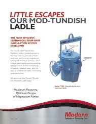
2.2.8 Monolithics<br />
Monolithic refractories are single piece casts in the shape of equipment, such as a ladle as shown<br />
in Figure 9. They are rapidly replacing the conventional type fired refractories in many<br />
applications including industrial furnaces. The main advantages of monolithics are:<br />
• Elimination of joints which is an inherent weakness<br />
• Faster application method<br />
• Special skill for installation not required<br />
• Ease of transportation and handling<br />
• Better scope to reduce downtime for repairs<br />
• Considerable scope to reduce inventory and eliminate special shapes<br />
• Heat savings<br />
• Better spalling resistance<br />
• Greater volume stability<br />
Monolithics are put into place using various methods, such as ramming, casting, gunniting,<br />
spraying, and sand slinging. Ramming requires proper tools and is mostly used in cold<br />
applications where proper consolidation of the material is important. Ramming is also used for<br />
air setting and heat setting materials. Because calcium aluminate cement is the binder, it will<br />
have to be stored properly to prevent moisture absorption. Its strength starts deteriorating after 6<br />
to 12 months.<br />
Figure 9. A Monolithic Lining for Ladel<br />
Energy Efficiency Guide for Industry in Asia - www.energyefficiencyasia.org ©UNEP 2006 14
Thermal Energy Equipment: Furnaces and Refractories<br />
2.3 Insulating materials 4<br />
Insulating materials greatly reduce the heat losses through walls. Insulation is achieved by<br />
providing a layer of material with low heat conductivity between the internal hot surface of a<br />
furnace and the external surface, thus keeping the temperature of the external surface low.<br />
Insulating materials may be classified into the following groups:<br />
• Insulating bricks<br />
• Insulating castables<br />
• Ceramic fiber<br />
• Calcium silicate<br />
• Ceramic coating<br />
Insulating materials owe their low conductivity to their pores while their heat capacity depends<br />
on the bulk density and specific heat. Air insulating materials consist of minute pores filled with<br />
air, which have a very low thermal conductivity. Excessive heat affects all insulation material<br />
adversely, but at what temperatures this takes place varies widely. Therefore the choice of an<br />
insulating material must be based on its ability to resist heat conductivity and on the highest<br />
temperature it will withstand. One of the most widely used insulating materials is diatomite, also<br />
known as kiesel guhr, which consists of a mass of skeletons of minute aquatic plants deposited<br />
thousands of years ago on the beds of seas and lakes. Its chemical composition is silica<br />
contaminated with clay and organic matter. A wide range of insulating refractories with wide<br />
combinations of properties is now available. Table 6 shows important physical properties of<br />
some insulating refractories.<br />
Type<br />
Table 6. Physical properties of insulating materials (BEE, 2005)<br />
Thermal Max. safe Cold crushing Porosity<br />
conductivity at temperature ( o C) strength percent<br />
400 o C<br />
(kg/cm 2 )<br />
Bulk<br />
density<br />
(kg/m 3 )<br />
Diatomite Solid 0.025 1000 270 52 1090<br />
Grade<br />
Diatomite 0.014 800 110 77 540<br />
Porous Grade<br />
Clay 0.030 1500 260 68 560<br />
High Alumina 0.028 1500-1600 300 66 910<br />
Silica 0.040 1400 400 65 830<br />
2.3.1 Castables and concretes<br />
Monolithic linings of furnace sections can be constructed by casting refractory insulating<br />
concretes, and stamping lightweight aggregates into place that are suitably bonded. Other<br />
applications include the bases of tunnel kiln cars used in the ceramic industry. The ingredients<br />
are similar to those insulation materials used for making piece refractories, except that concretes<br />
contain either Portland or high-alumina cement.<br />
4 Section 2.3 is taken (with edits) from Energy Efficiency in Thermal Utilities, 2005 with permission from the Bureau of Energy<br />
Efficiency, Ministry of Power, India.<br />
Energy Efficiency Guide for Industry in Asia - www.energyefficiencyasia.org ©UNEP 2006 15
Thermal Energy Equipment: Furnaces and Refractories<br />
2.3.2 Ceramic fiber<br />
Ceramic fiber is a low thermal mass insulation material, which has revolutionized furnace design<br />
lining systems. Ceramic fiber is manufactured by blending and melting alumina and silica at a<br />
temperature of 1800 – 2000 o C, and breaking the molten stream by blowing compressed air or<br />
dropping the molten stream on a spinning disc to form loose or bulk ceramic fiber. The bulk<br />
fiber is used to produce various insulation products including blankets, strips, veneering and<br />
anchored modules, paper, vacuum formed boards and shapes, ropes, wet felt, mastic cement etc.<br />
Fibers are usually produced in two temperature grades based on Al 2 O 3 content. A new product is<br />
ZrO 2 added alumino-silicate fiber, which helps to reduce shrinkage levels and thereby making<br />
the fiber suitable for higher temperatures. Continuous recommended operating temperature for<br />
fibers are given in the Table 7.<br />
Table 7. Continuous recommended operating temperature for fibers (BEE, 2005)<br />
Al 2 O 3 SiO 2 ZrO 2<br />
1150 o C 43 – 47 percent 53 – 57 percent -<br />
1250 o C 52 – 56 percent 44 – 48 percent -<br />
1325 o C 33 – 35 percent 47 – 50 percent 17 – 20 percent<br />
Ceramic fibers are generally produced in bulk wool form and needled into a blanket mass of<br />
various densities ranging from 64 to 190 kg/m 3 . Converted products and over 40 different forms<br />
are made from blankets to suit various requirements.<br />
The characteristics of ceramic fibers are a remarkable combination of the properties of<br />
refractories and traditional insulation material.<br />
a) Lower thermal conductivity<br />
Because of the low thermal conductivity (0.1 kCal/m per hour per o C at 600 o C for a blanket with<br />
128 kg/m 3 density) it is possible to construct thinner linings with the same thermal efficiency as<br />
conventional refractories. As a result of thinner lining, the furnace volume is higher. It is 40<br />
percent more effective than good quality insulation brick and 2.5 times better than asbestos.<br />
Ceramic fiber is a better insulator than calcium silicate.<br />
b) Light weight<br />
The average density of ceramic fiber is 96 kg/m 3 . It is one tenth of the weight of insulating brick<br />
and one third of the weight of asbestos / calcium silicate boards. For new furnaces structural<br />
supports can be reduced by 40 percent.<br />
c) Lower heat storage<br />
Ceramic fiber linings absorb less heat because of their lower density. Furnaces can therefore be<br />
heated and cooled at faster rates. Typically the heat stored in a ceramic fiber lining system is in<br />
the range of 2700 - 4050 kCal/m 2 (1000 – 1500 Btu/Ft 2 ) as compared to 54200-493900 kCal/m 2<br />
(20000 – 250000 Btu/Ft 2 ) for conventionally lined systems.<br />
Energy Efficiency Guide for Industry in Asia - www.energyefficiencyasia.org ©UNEP 2006 16
Thermal Energy Equipment: Furnaces and Refractories<br />
d) Thermal shock resistant<br />
Ceramic fiber linings resist thermal shock due to their resilient matrix. This also allows for<br />
faster heat up and cool down cycles, thereby improving furnace availability and productivity.<br />
e) Chemical resistance<br />
Ceramic fiber resist most of the chemical attack and is unaffected by hydrocarbons, water and<br />
steam present in flue gases.<br />
f) Mechanical resilience<br />
The high mechanical resilience of ceramic fiber makes it possible to manufacture fiber-lined<br />
furnaces off-site, transport them to the site in assembled form without the risk of damage.<br />
g) Low installation cost<br />
As the application of ceramic fibers is a standardized process, no special skills are required.<br />
Fiber linings require no dry out or curing times and there is no risk of cracking or spalling when<br />
they are heated after installation.<br />
h) Ease of maintenance<br />
In case of physical damage, the section of damaged ceramic fiber can be quickly removed and<br />
replaced with a new piece. Entire panel sections can be prefabricated for fast installation with<br />
minimal down time.<br />
i) Ease of handling<br />
All product forms are easily handled and most can be quickly cut with a knife or scissors.<br />
Vacuum formed products may require cutting with a band saw.<br />
j) Thermal efficiency<br />
Thermal efficiency of a furnace lined with ceramic fiber is improved in two ways. First, the low<br />
thermal conductivity of ceramic fiber allows the lining to be thinner and therefore the furnace<br />
can be smaller. Second, the fast response of ceramic fiber to temperature changes also allows for<br />
more accurate control and uniform temperature distribution within the furnace.<br />
Other advantages offered by ceramic fiber are:<br />
• Lightweight furnace<br />
• Simple steel fabrication work<br />
• Low down time<br />
• Increased productivity<br />
• Additional capacity<br />
• Low maintenance cost<br />
• Longer service life<br />
• Higher thermal efficiency<br />
• Faster response<br />
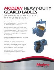
2.3.3 High emissivity coatings<br />
Emissivity (i.e. the measure of a material’s ability to both absorb and radiate heat) is often<br />
considered as an inherent physical property that does not normally change (other examples are<br />
density, specific heat and thermal conductivity). However, the development of high emissivity<br />
Energy Efficiency Guide for Industry in Asia - www.energyefficiencyasia.org ©UNEP 2006 17
Thermal Energy Equipment: Furnaces and Refractories<br />
coatings allows the surface emissivity of materials to be increased. High emissivity coatings are<br />
applied on the interior surface of furnaces. Figure 10 shows that the emissivity of various<br />
insulating materials reduces with increasing process temperatures. The advantage of high<br />
emissivity coatings is that the emissivity remains more or less constant.<br />
The emissivity of furnaces that operate at high temperatures is 0.3. By using high emissivity<br />
coatings this can go up to 0.8, resulting in an increase of heat transfer through radiation.<br />
Other benefits of high emissivity coatings in furnace chambers are uniform heating and extended<br />
life of refractories and metallic components such as radiant tubes and heating elements. For<br />
intermittent furnaces or where rapid heating is required, use of such coatings was found to reduce<br />
fuel or power by 25 - 45 percent.<br />
Figure 10. Emissivity of Refractory Materials at Different<br />
Temperatures (BEE, 2005)<br />
3. ASSESSMENT OF <strong>FURNACES</strong><br />
This section describes the various methods and techniques used to quantify the losses from the<br />
furnace and the methods to carry out performance assessment of typical furnaces.<br />
3.1 Heat losses affecting furnace performance<br />
Ideally, all heat added to the furnaces should be used to heat the load or stock. In practice,<br />
however, a lot of heat is lost in several ways as shown in Figure 11.<br />
Energy Efficiency Guide for Industry in Asia - www.energyefficiencyasia.org ©UNEP 2006 18
Thermal Energy Equipment: Furnaces and Refractories<br />
Heat input<br />
FURNACE<br />
Heat in stock<br />
Other losses<br />
Furnace surface/skin<br />
Openings in furnace<br />
Hydrogen in fuel<br />
Moisture in fuel<br />
Flue gas<br />
Figure 11. Heat Losses in a Furnace<br />
These furnace heat losses include (BEE, 2005 and US DOE, 2004):<br />
• Flue gas losses: part of the heat remains in the combustion gases inside the furnace. This<br />
loss is also called waste-gas loss or stack loss.<br />
• Loss from moisture in fuel: fuel usually contains some moisture and some of the heat is used<br />
to evaporate the moisture inside the furnace<br />
• Loss due to hydrogen in fuel which results in the formation of water<br />
• Loss through openings in the furnace: radiation loss occurs when there are openings in the<br />
furnace enclosure and these losses can be significant, especially for furnaces operating at<br />
temperatures above 540°C. A second loss is through air infiltration because the draft of<br />
furnace stacks/chimneys cause a negative pressure inside the furnace, drawing in air through<br />
leaks or cracks or when ever the furnace doors are opened.<br />
• Furnace skin / surface losses, also called wall losses: while temperatures inside the furnace<br />
are high, heat is conducted through the roof, floor and walls and emitted to the ambient air<br />
once it reaches the furnace skin or surface.<br />
• Other losses: there are several other ways in which heat is lost from a furnace, although<br />
quantifying these is often difficult. Some of these include<br />
− Stored heat losses: when the furnace is started the furnace structure and insulation is also<br />
heated, and this heat only leaves the structure again when the furnace shuts down.<br />
Therefore this type of heat loss increases with the number of times the furnace is turned<br />
on and off<br />
− Material handling losses: the equipment used to move the stock through the furnace, such<br />
as conveyor belts, walking beams, bogies etc, also absorb heat. Every time equipment<br />
leave the furnace they loose their heat, therefore heat loss increases with the amount of<br />
equipment and the frequency by which they enter and leave the furnace<br />
Energy Efficiency Guide for Industry in Asia - www.energyefficiencyasia.org ©UNEP 2006 19
Thermal Energy Equipment: Furnaces and Refractories<br />
− Cooling media losses: water and air are used to cool down equipment, rolls, bearing and<br />
rolls, but heat is lost because these media absorb heat<br />
− Incomplete combustion losses: heat is lost if combustion is incomplete because unburnt<br />
fuel or particles have absorbed heat but this heat has not been put to use<br />
− Loss due to formation of scales<br />
3.2 Instruments to assess furnace performance 5<br />
Furnace efficiency is calculated after subtracting the various heat losses. In order to find out<br />
furnace efficiency using the indirect method, various parameters must be measured, such as<br />
hourly furnace oil consumption, material output, excess air quantity, temperature of flue gas,<br />
temperature of furnace at various zones, and others. Date for some of these parameters can be<br />
obtained from production records while others must be measured with special monitoring<br />
instruments. Table 8 lists the instruments that are needed to measure these parameters.<br />
Table 8. Instruments for Measuring Furnace Performance Parameter (BEE, 2005)<br />
Parameters<br />
to be measured<br />
Location of<br />
measurement<br />
Instrument<br />
required<br />
Required<br />
Value<br />
1200-1300 o C<br />
Furnace soaking zone<br />
temperature (reheating<br />
furnaces)<br />
Flue gas temperature<br />
Soaking zone and side<br />
wall<br />
In duct near the discharge<br />
end, and entry to<br />
recuperator<br />
Pt/Pt-Rh thermocouple<br />
with indicator and<br />
recorder<br />
Chromel Alummel<br />
Thermocouple with<br />
indicator<br />
Flue gas temperature After recuperator Hg in steel thermometer<br />
700 o C max.<br />
300 o C (max)<br />
Furnace hearth pressure<br />
in the heating zone<br />
Near charging end and<br />
side wall over the hearth<br />
Low pressure ring gauge<br />
+0.1 mm of Wc<br />
Oxygen in flue gas<br />
In duct near the discharge<br />
end<br />
Fuel efficiency monitor<br />
for oxygen and<br />
temperature<br />
Billet temperature Portable Infrared pyrometer or<br />
optical pyrometer<br />
5% O2<br />
-<br />
3.3 Calculating furnace performance<br />
A furnace’s efficiency increases when the percentage of heat that is transferred to the stock or<br />
load inside the furnace increases. The efficiency of the furnace can be calculated in two ways,<br />
similar to that of the boiler: direct method and indirect method. Both methods are explained<br />
below.<br />
5 Sections 3.2 is taken (with edits) from Energy Efficiency in Thermal Utilities, 2005 with permission from the Bureau of Energy<br />
Efficiency, Ministry of Power, India.<br />
Energy Efficiency Guide for Industry in Asia - www.energyefficiencyasia.org ©UNEP 2006 20
Thermal Energy Equipment: Furnaces and Refractories<br />
3.3.1 Direct method<br />
The efficiency of a furnace can be determined by measuring the amount heat absorbed by the<br />
stock and dividing this by the total amount of fuel consumed.<br />
Thermal efficiency of the furnace =<br />
Heat in the stock<br />
Heat in the fuel consumed for heating the stock<br />
The quantity of heat (Q) that will be transferred to stock can be calculated with this equation:<br />
Q = m x C p (t 1 – t 2 )<br />
Where, Q = Quantity of heat of stock in kCal<br />
m = Weight of the stock in kg<br />
C p = Mean specific heat of stock in kCal/kg o C<br />
t 1 = Final temperature of stock in o C<br />
t 2 = Initial temperature of the stock before it enters the furnace in o C<br />
An example calculation is given in section 3.3.3.<br />
3.3.2 Indirect method<br />
The furnace efficiency can also be determined through the indirect method, similar to the<br />
evaluation of boiler efficiency. The principle is simple: the heat losses are substracted from the<br />
heat supplied to the furnace. Different types of heat losses are illustrated in Figure 11. Typical<br />
thermal efficiencies for common industrial furnaces are given in the Table 9.<br />
Table 9. Thermal Efficiencies for Common Industrial Furnaces (BEE 2005)<br />
Furnace type<br />
Typical thermal efficiencies (percent)<br />
1) Low Temperature furnaces<br />
a. 540 – 980 o C (Batch type) 20-30<br />
b. 540 – 980 o C (Continous type) 15-25<br />
c. Coil Anneal (Bell) radiant type 5-7<br />
d. Strip Anneal Muffle 7-12<br />
2) High temperature furnaces<br />
a. Pusher, Rotary 7-15<br />
b. Batch forge 5-10<br />
3) Continuous Kiln<br />
a. Hoffman 25-90<br />
b. Tunnel 20-80<br />
4) Ovens<br />
a. Indirect fired ovens (20 o C –370 o C) 35-40<br />
b. Direct fired ovens (20 o C –370 o C) 35-40<br />
Energy Efficiency Guide for Industry in Asia - www.energyefficiencyasia.org ©UNEP 2006 21
Thermal Energy Equipment: Furnaces and Refractories<br />
An example calculation using the indirect method is given in the next section.<br />
3.3.3 Example calculation of furnace efficiency<br />
Calculate the efficiency of an oil-fired reheating furnace with the direct and indirect method<br />
using the data below.<br />
Operating temperature:<br />
1340 o C<br />
Exit flue gas temperature after preheater: 750 o C<br />
Ambient temperature:<br />
40 o C<br />
Preheated air temperature:<br />
190 o C<br />
Specific gravity of fuel oil: 0.92<br />
Average fuel oil consumption:<br />
400 liters / hr = 400 x 0.92 =368 kg/hr<br />
Calorific value of oil<br />
10000 kCal/kg<br />
Average O 2 percentage in flue gas: 12 percent<br />
Moisture in 1 kg of fuel oil:<br />
0.15 kg<br />
H 2 in 1 kg of fuel oil:<br />
0.1123 kg<br />
Theoretical air required to burn 1 kg of oil: 14 kg<br />
Weight of stock:<br />
6000 kg/hr<br />
Specific heat of billet:<br />
0.12 kCal/kg/ 0 C<br />
Furnace wall thickness (D):<br />
460 mm<br />
Billet extraction outlet (X):<br />
1 m x 1 m<br />
Average surface temperature<br />
of heating + soaking zone:<br />
122 o C<br />
Average surface temperature of area<br />
other than heating and soaking zone: 80 o C<br />
Area of heating + soaking zone: 70.18 m 2<br />
Area other than heating and soaking zone: 12.6 m 2<br />
Direct method calculation<br />
The heat input is 400 liters per hour. The specific gravity of fuel is used to convert this into kg.<br />
Therefore: 400 l/hr x 0.92 kg/l = 368 kg/hr<br />
The heat output is calculated as follows:<br />
= m x Cp x ΔT<br />
= 6000 kg x 0.12 x (1340 – 40)<br />
= 936000 kCal<br />
The efficiency is:<br />
= (heat input / heat output) x 100<br />
= [(936000 / (368 x 10000)] x 100 = 25.43 percent<br />
The approximate heat loss is 100% – 25% = 75%<br />
Indirect method<br />
Energy Efficiency Guide for Industry in Asia - www.energyefficiencyasia.org ©UNEP 2006 22
Thermal Energy Equipment: Furnaces and Refractories<br />
The different heat losses are calculated below.<br />
a) Heat loss in flue gas<br />
Excess air (EA)<br />
= O 2 percent / (21 – O 2 percent)<br />
= 12 / (21 – 12)<br />
= 133 %<br />
Mass of air supplied<br />
= (1 + EA/100) x Theoretical air<br />
= (1+ 1.13) x 14<br />
= 32.62 kg/kg fuel oil<br />
% Heat loss in flue gas =<br />
m x C p x ΔT x 100<br />
GCV of fuel<br />
Where,<br />
m = weight of flue gas (air + fuel) = 32.62 + 1.0 = 33.62 kg/kg oil<br />
C p = specific heat<br />
ΔT = temperature difference<br />
% Heat loss = {33.62 x 0.24 x (750 – 40)} x 100 = 57.29%<br />
10000<br />
b) Heat loss from moisture in fuel<br />
% Heat loss from moisture in fuel =<br />
M x {584 + C p (T f – T amb )} x 100<br />
GCV of fuel<br />
Where,<br />
M = kg of moisture in 1 kg of fuel oil<br />
T fg = Flue gas temperature, 0 C<br />
T amb = Ambient temperature, 0 C<br />
GCV = Gross Calorific Value of fuel, kCal/kg<br />
% Heat loss = 0.15 x {584 + 0.45 (750 – 40)} x 100 = 1.36%<br />
10000<br />
Energy Efficiency Guide for Industry in Asia - www.energyefficiencyasia.org ©UNEP 2006 23
Thermal Energy Equipment: Furnaces and Refractories<br />
c) Loss due to hydrogen in fuel<br />
% Heat loss due to hydrogen in fuel =<br />
9 x H 2 x {584 + C p (T f – T amb )} x 100<br />
GCV of fuel<br />
Where,<br />
H 2 = kg of H 2 in 1 kg of fuel oil (= 0.1123 kg/kg of fuel oil)<br />
% Heat loss = 9 x 0.1123 x {584 + 0.45 (750 – 40)} x 100 = 9.13%<br />
10000<br />
d) Heat loss due to openings in furnace<br />
% Heat loss from openings in<br />
furnace =<br />
(Black body radiation factor x emissivity x<br />
factor of radiation x area of opening) x 100<br />
Quantity of oil x GCV of oil<br />
The factor of radiation through openings and the black body radiation factor can be obtained<br />
from standard graphs as shown in Figure 12 and Figure 13.<br />
• Factor of radiation (refer Figure 12) = 0.71<br />
• Black body radiation at 1340 0 C (refer Figure 13) = 36 kCal/kg/cm2/hr<br />
• The area of the opening is 100 cm x 100 cm = 10000 cm 2<br />
• Emissivity = 0.8<br />
% Heat loss from furnace openings = 36 x 0.8 x 0.71 x 10000 x 100 = 5.56%<br />
368 x 10000<br />
Energy Efficiency Guide for Industry in Asia - www.energyefficiencyasia.org ©UNEP 2006 24
Thermal Energy Equipment: Furnaces and Refractories<br />
Figure 12. Radiation Factor for Heat Release through Openings relative to<br />
the Quality of Heat Release from Perfect Black Body (BEE, 2005)<br />
Figure 13. Black Body Radiation at Different Temperatures (BEE, 2005)<br />
Energy Efficiency Guide for Industry in Asia - www.energyefficiencyasia.org ©UNEP 2006 25
Thermal Energy Equipment: Furnaces and Refractories<br />
e) Heat loss through furnace skin<br />
To determine the heat loss through the furnace skin, first the heat loss through the roof and<br />
sidewalls and through other areas must be calculated separately.<br />
i). Heat loss through roof/ceiling and sidewalls (= heating and soaking zone):<br />
• Total average surface temperature = 122 o C<br />
• Heat loss at 122 o C (Refer Figure 14) = 1252 kCal /m 2 hr<br />
• Total area of heating + soaking zone = 70.18 m 2<br />
Heat loss through furnace roof =<br />
Heat loss from roof and walls<br />
Area of roof and walls<br />
Total heat loss = 1252 kCal / m 2 hr x 70.18 m 2 = 87865 kCal/hr<br />
ii) Heat lost from area other than heating and soaking zone<br />
• Total average surface temperature = 80 oC<br />
• Heat loss at 80 o C (Refer Figure 14) = 740 kCal / m 2 hr<br />
• Total area = 12.6 m 2<br />
Heat loss through other areas =<br />
Heat loss from roof other areas<br />
Area of other areas<br />
Total heat loss = 740 kCal / m 2 hr x 12.6 m 2 = 9324 kCal/hr<br />
(Heat loss i + heat loss ii) x 100<br />
% Heat loss through furnace skin = GCV of oil x Quantity of oil per hour<br />
% Heat loss through furnace skin = (87865 kCal/hr + 9324 kCal/hr) x 100 = 2.64%<br />
10000 kCal/kg x 368 kg/hr<br />
f) Unaccounted losses<br />
The unaccounted losses cannot be calculated unless the other types of losses are known.<br />
Furnace efficiency<br />
Adding the losses a to f up gives the total losses:<br />
a) Flue gas loss = 57.29 %<br />
Energy Efficiency Guide for Industry in Asia - www.energyefficiencyasia.org ©UNEP 2006 26
Thermal Energy Equipment: Furnaces and Refractories<br />
b) Loss due to moisture in fuel = 1.36 %<br />
c) Loss due to H2 in fuel = 9.13 %<br />
d) Loss due to openings in furnace = 5.56 %<br />
e) Loss through furnace skin = 2.64 %<br />
Total losses = 75.98 %<br />
The furnace efficiency calculated through the indirect method = 100 – 75.98 = 24.02%<br />
Figure 14. Heat Loss from the Ceiling, Sidewall and Hearth of Furnace (BEE, 2005)<br />
4. ENERGY EFFICIENCY OPPORTUNITES<br />
This section explains the various energy saving opportunities in furnaces. 6 Typical energy<br />
efficiency measures for an industry with furnace are:<br />
1. Complete combustion with minimum excess air<br />
2. Proper heat distribution<br />
3. Operation at the optimum furnace temperature<br />
4. Reducing heat losses from furnace openings<br />
5. Maintaining correct amount of furnace draft<br />
6. Optimum capacity utilization<br />
7. Waste heat recovery from the flue gases<br />
8. Minimum refractory losses<br />
9. Use of ceramic coatings<br />
10. Selecting the right refractories<br />
6 Section 4 is taken and adapted from Energy Efficiency in Thermal Utilities (2005) with permission from the<br />
Bureau of Energy Efficiency, Ministry of Power, India<br />
Energy Efficiency Guide for Industry in Asia - www.energyefficiencyasia.org ©UNEP 2006 27
Thermal Energy Equipment: Furnaces and Refractories<br />
4.1 Complete combustion with minimum excess air<br />
The amount of heat lost in the flue gases (stack losses) depends on the amount of excess air. To<br />
obtain complete combustion of fuel with the minimum amount of air, it is necessary to control<br />
air infiltration, maintain pressure of combustion air, fuel quality and monitor the amount excess<br />
air. Too much excess air will reduce flame temperature, furnace temperature and heating rate.<br />
Too little excess air will result in an increase in unburnt components in flue gases that are carried<br />
away through the stack and it also causes more scale losses.<br />
Optimizing combustion air is the most attractive and economical measure for energy<br />
conservation. Potential savings are higher when the temperature of furnace is high. The air ratio<br />
(= actual air amount / theoretical combustion air amount) gives an indication of excess air air. If<br />
a reheating furnace is not equipped with an automatic air/fuel ratio controller, it is necessary to<br />
periodically take a sample of gas in the furnace and measure its oxygen contents with a gas<br />
analyzer.<br />
4.2 Proper heat distribution<br />
A furnace should be designed to ensure that within a given time the stock is heated uniformly to<br />
a desired temperature with the minimum amount of fuel.<br />
Where burners are used to fire the furnace, the following should be ensured for proper heat<br />
distribution:<br />
• The flame should not touch or be obstructed by any solid object. Obstruction causes the fuel<br />
particles to de-atomize, which affects combustion and causes black smoke. If the flame<br />
impinges on the stock scale losses will increase. If the flame impinges on refractories,<br />
products from incomplete combustion can settle and react with the refractory constituents at<br />
high temperatures.<br />
• The flames of different burners should stay clear of each other, as intersecting flames cause<br />
incomplete combustion. It is also desirable to stagger burners on opposite sides.<br />
• The burner flame has a tendency to travel freely in the combustion space just above the<br />
material. For this reason, the axis of the burner in small furnaces is never placed parallel to<br />
the hearth but always at an upward angle, but the flame should not hit the roof.<br />
• Large burners produce longer flames, which may be difficult to contain within the furnace<br />
walls. More burners of less capacity ensure a better heat distribution inside the furnace and<br />
also increase the furnace life.<br />
• In small furnaces that use furnace oil, a burner with a long flame with a golden yellow color<br />
improves uniform heating. But the flame should not be too long, because heat is lost of the<br />
flame reaches the chimney or the furnace doors.<br />
4.3. Operation at the optimum furnace temperature<br />
It is important to operate the furnace at its optimum temperature. Operating temperatures of<br />
various furnaces are given in Table 10. Operating at too high temperatures causes heat loss,<br />
excessive oxidation, de-carbonization and stress on refractories. Automatic control of the furnace<br />
temperature is preferred to avoid human error.<br />
Energy Efficiency Guide for Industry in Asia - www.energyefficiencyasia.org ©UNEP 2006 28
Thermal Energy Equipment: Furnaces and Refractories<br />
Table 10. Operating Temperatures of Various Furnaces<br />
Slab Reheating furnaces 1200 o C<br />
Rolling Mill furnaces<br />
Bar furnace for Sheet Mill<br />
Bogie type annealing furnaces<br />
1200 o C<br />
800 o C<br />
650 o C –750 o C<br />
4.4. Prevent heat loss through openings<br />
Heat can be lost by direct radiation through openings in the furnace, such as the charging inless,<br />
extracting outlet and the peephole in the wall or ceiling. Heat is also lost due to pressure<br />
differences between the inside of the furnace and the ambient environment causing combustion<br />
gases to leak through the openings. But most heat is lost if outside air infiltrates into the furnace,<br />
because in addition to heat loss this also causes uneven temperatures inside the furnace and stock<br />
and can even lead to oxidization of billets.<br />
It is therefore important to keep the openings as small as possible and to seal them. Another<br />
effective way to reduce the heat loss through furnace openings is by opening the furnace doors<br />
less frequent and for the shortest time period as possible (another option is described under item<br />
4.5). This heat loss is about 1 percent of the total quantity of heat generated in the furnace, if<br />
furnace pressure is controlled properly.<br />
Section 3.3.3 already explained one way of calculating heat loss through openings. But an<br />
alternative way is calculating heat loss with the following equation:<br />
Where,<br />
Q = heat loss<br />
T = absolute temperature (K)<br />
a = factor for total radiation<br />
A = area of opening, m 2<br />
H = time (hours)<br />
For example, a reheating furnace with a temperature of 1340 oC, the wall thickness is 460 mm<br />
(X) and the door is 1 m high (D) by 1 m wide. D/X = 1/0.460 = 0.71, and in Figure 12 this<br />
corresponds with a factor for total radiation of 0.71. The heat loss from openings in therefore:<br />
Energy Efficiency Guide for Industry in Asia - www.energyefficiencyasia.org ©UNEP 2006 29
Thermal Energy Equipment: Furnaces and Refractories<br />
4.5. Control of furnace draft<br />
If negative pressures exist inside the furnace, air can infiltrate through cracks and openings and<br />
affect the air-fuel ratio control. This in turn can cause metal to not reach the desired temperature<br />
or non-uniform temperatures, which affects the next processes like forging and rolling. Fuel<br />
consumption and product rejection rates increase. Tests conducted on seemingly airtight furnaces<br />
have shown air infiltration up to 40 percent. To avoid this, slight positive pressure should be<br />
maintained inside the furnace (in addition to the measures mentioned under 4.4).<br />
But the pressure difference should not be too high because this will cause ex-filtration. While<br />
this is less of a problem than infiltration, it can still result in flames reaching out of the furnace,<br />
overheating of refractories leading to reduced brick life, increased furnace maintenance, and<br />
burnout of ducts and equipment.<br />
Proper management of the pressure difference between the inside and outside of the furnace is<br />
therefore important to minimize heat loss and adverse impacts on products.<br />
4.6. Optimum capacity utilization<br />
One of the most vital factors affecting the furnace efficiency is the load. This includes the<br />
amount of material placed in the furnace, the arrangement inside the furnace and the residence<br />
time inside the furnace.<br />
a) Optimum load<br />
If the furnace is under loaded the proportion of total heat available that will be taken up by the<br />
load is smaller, resulting in a lower efficiency. Overloading can lead to the load not heated to the<br />
right temperature within a given period of time.<br />
There is a particular load at which the furnace will operate at maximum thermal efficiency, i.e.<br />
where the amount of fuel per kg of material is lowest. This load is generally obtained by<br />
recording the weight of material of each charge, the time it takes to reach the right temperature,<br />
and the amount of fuel used. The furnace should be loaded to the optimum load at all times,<br />
although in practice this may not always be possible.<br />
b) Optimum arrangement of the load<br />
The loading of materials on the furnace hearth should be arranged so that<br />
• It receives the maximum amount of radiation from the hot surfaces of the heating chambers<br />
and flames<br />
• Hot gases are efficiently circulated around the heat receiving surfaces of the materials<br />
• Stock is not placed in the following position:<br />
− In the direct path of the burners or where flame impingement is likely to occur<br />
− In an area that is likely to cause a blockage or restriction of the flue system of the furnace<br />
− Close to any door openings where cold spots are likely to develop<br />
Energy Efficiency Guide for Industry in Asia - www.energyefficiencyasia.org ©UNEP 2006 30
Thermal Energy Equipment: Furnaces and Refractories<br />
c) Optimum residence time of the load<br />
Fuel consumption is kept at a minimum and product quality is best if the load only remains<br />
inside the furnace until it has the required physical and metallurgical properties.<br />
Sometimes the charge and production schedule does not correspond with the capacity of the<br />
furnace. If this is the case, either the<br />
• Load is higher or lower than the optimum load<br />
• Residence time is longer or shorter than the ideal residence time. Excessive residence time<br />
will increase oxidation of the material surface, which can result in rejection of products. The<br />
rate of oxidation is dependent upon time, temperature, as well as free oxygen content<br />
• Temperature is increased to make up for shorter residence time. The higher the working<br />
temperature, the higher is the loss per unit of time.<br />
All three result in fuel wastage and sometimes in reduced product quality. Coordination between<br />
the furnace operator, production and planning personnel is therefore essential.<br />
Optimum utilization of furnace can be planned at design stage, by selecting the size and type<br />
(batch, continuous) that best matches the production schedule.<br />
The overall efficiency of a continuous type furnace will increase with heat recuperation from the<br />
waste gas stream. If only batch type furnace is used, careful planning of the loads is important.<br />
Furnace should be recharged as soon as possible to enable use of residual furnace heat.<br />
4.7. Waste heat recovery from furnace flue gases<br />
In any industrial furnace the combustion products leave the furnace at a temperature higher than<br />
the stock temperature. Flue gases carry 35 to 55 percent of the heat input to the furnace with<br />
them through the chimney. The higher the amount of excess air and flue gas temperature, the<br />
higher the amount of waste heat that is available. However, the primary objective should be to<br />
minimize the amount of waste heat generated through energy conservation measures. Waste heat<br />
recovery should only be considered when further energy conservation is not possible or practical.<br />
Waste heat in flue gases can be recovered for preheating of the charge (stock, load), preheating<br />
of combustion air or for other processes as described below.<br />
a) Charge pre-heating<br />
When raw materials are preheated by exhaust gases before being placed in a heating furnace, the<br />
amount of fuel necessary to heat them in the furnace is reduced. Since raw materials are usually<br />
at room temperature, they can be heated sufficiently using high-temperature flue gases to<br />
noticeably reduce the fuel consumption rate.<br />
b) Preheating of combustion air<br />
For a long time, fuel gases were only use for preheating of combustion air for large boilers,<br />
metal-heating furnaces and high-temperature kilns. But preheating using heat from flue gases is<br />
now also applied to compact boilers and compact industrial furnaces.<br />
Energy Efficiency Guide for Industry in Asia - www.energyefficiencyasia.org ©UNEP 2006 31
Thermal Energy Equipment: Furnaces and Refractories<br />
A variety of equipment is available to recover waste heat. External recuperators are most<br />
common, but other techniques are also used, such as self-recuperative burners. For example, a<br />
modern recuperator use furnace exhaust gas of 1000°C can preheat the combustion air to over<br />
500 o C, which results in energy savings of up to 30 percent compared with using cold<br />
combustion air entering the furnace.<br />
Since the volume of combustion air increases when it is preheated, it is necessary to consider this<br />
when modifying air-duct diameters and blowers. It should be noted that preheating of<br />
combustion gases from high-density oils with a high sulphur content, could cause clogging with<br />
dust or sulphides, corrosion or increases in nitrogen oxides.<br />
c) Utilizing waste heat as a heat source for other processes<br />
Other process (to generate steam or hot water by a waste heat boiler)<br />
The temperature of furnace exhaust gas can be as high as 400- 600 °C, even after heat has been<br />
recovered from it for preheating the charge or combustion air. One possibility is to install a waste<br />
heat boiler to produce steam or hot water from this heat, especially when large quantities steam<br />
or hot water are needed in a plant. Sometimes exhaust gas heat can be used for heating purposes<br />
in other equipment, but only if the heat quantity, temperature range, operation time etc are<br />
suitable for this. Fuel consumption can be greatly reduced. One existing example is the use of<br />
exhaust gas from a quenching furnace as a heat source in a tempering furnace.<br />
4.8. Minimizing furnace skin losses<br />
About 30 to 40 percent of the fuel used in intermittent or continuous furnaces is used to make up<br />
for heat lost through the furnace skin/surface or walls. The extent of wall losses depend on:<br />
• Emissivity of wall<br />
• Thermal conductivity of refractories<br />
• Wall thickness<br />
• Whether the furnace is operated continuously or intermittently<br />
There are several ways to minimize heat loss through the furnace skin:<br />
• Choosing the appropriate refractory materials<br />
• Increasing the wall thickness<br />
• Installing insulating bricks. Outside wall temperatures and heat losses of a composite wall<br />
are much lower for a wall of firebrick and insulation brick compared to a wall of the same<br />
thickness that consists only of refractory bricks. The reason is that insulating bricks have a<br />
much lower conductivity.<br />
• Planning operating times of furnaces. For most small furnaces, the operating periods<br />
alternate with the idle periods. When the furnaces are turn off, heat that was absorbed by the<br />
refractories during operation gradually dissipates through radiation and convection from the<br />
cold face and through air flowing through the furnace. When the furnace is turned on again,<br />
additional fuel is needed to heat up the refractories again. If a furnace is operated<br />
continuously for 24 hours in three days, practically all the heat stored in the refractories is<br />
lost. But if the furnace is operated 8 hours per day all the heat stored in the refractories is not<br />
dissipated. For a furnace with a firebrick wall of 350 mm thickness, it is estimated that during<br />
Energy Efficiency Guide for Industry in Asia - www.energyefficiencyasia.org ©UNEP 2006 32
Thermal Energy Equipment: Furnaces and Refractories<br />
the 16 hours that the furnace is turned off, only 55 percent of the heat stored in the<br />
refractories is dissipated from the cold surface. Careful planning of the furnace operation<br />
schedule can therefore reduce heat loss and save fuel.<br />
The quantity (Q) of heat loss from the furnace skin is the sum of natural convection and thermal<br />
radiation. In addition to the method explain in section 3.3.3, the following equation can also be<br />
used:<br />
Where,<br />
Q = Quantity of heat released (kCal/hr)<br />
a = factor regarding direction of the surface of natural convection ceiling = 2.8,<br />
side walls = 2.2, hearth = 1.5<br />
tl = temperature of external wall surface of the furnace (°C), based on the average of as<br />
many measurements as possible to reduce the error margin<br />
t2 = temperature of air around the furnace (°C)<br />
E = emissivity of external wall surface of the furnace<br />
The first part of the equation gives the heat loss though natural convection, and the second part<br />
the heat loss through radiation. Figure 14 shows the relation between the temperature of external<br />
wall surface and the quantity of heat release calculated with this formula.<br />
An example calculation of the heat loss from a furnace’s surface is as follows:<br />
A reheating furnace has a ceiling, sidewalls and hearth with a 20 m 2 , 50 m 2 and 20 m 2 surface<br />
area respectively. Their average measured surface temperatures 80°C, 90°C and 100°C<br />
respectively. Based on Figure 14, the quantities of heat release from ceiling, sidewalls and hearth<br />
per unit area are respectively 650 kCal/m 2 h, 720 kCal/m 2 h and 730 kCal/m 2 h.<br />
Therefore, the total quantity of heat release Q<br />
= loss through ceiling + loss through sidewalls + loss through hearth<br />
= (650 x 20) + (720 x 50) + (730 x 20)<br />
= 13000 + 36000 +14600= 63,600 kCal/hr<br />
Energy Efficiency Guide for Industry in Asia - www.energyefficiencyasia.org ©UNEP 2006 33
Thermal Energy Equipment: Furnaces and Refractories<br />
Figure 15. Relationship between Surface Temperature and<br />
Quantity of Heat Loss (BEE, 2005)<br />
4.9 Use of ceramic coatings (high emissivity coatings)<br />
Ceramic coatings in the furnace chamber promote rapid and efficient transfer of heat, uniform<br />
heating and extended life of refractories. The emissivity of conventional refractories decreases<br />
with increase in temperature whereas for ceramic coatings it increases slightly. This outstanding<br />
property has been exploited by using ceramic coatings in hot face insulation. Ceramic coatings<br />
are high emissivity coatings and a have a long life at temperatures up to 1350 o C. There are two<br />
types of ceramic coatings: those used for coating metal substrates, and those used for coating<br />
refractory substrates. The coatings are non-toxic, non-flammable and water based. Applied at<br />
room temperatures, they are sprayed and air-dried in less than five minutes. The coatings allow<br />
the substrate to maintain its designed metallurgical properties and mechanical strength.<br />
Installation is quick and can be completed during shut down. Energy savings of the order of 8-20<br />
percent have been reported depending on the type of furnace and operating conditions. High<br />
emissivity coatings are further described in section 2.3.3.<br />
4.10 Selection of refractories<br />
The selection of refractories aims to maximize the performance of the furnace, kiln or boiler.<br />
Furnace manufacturers or users should consider the following points in the selection of a<br />
refractory:<br />
• Type of furnace<br />
Energy Efficiency Guide for Industry in Asia - www.energyefficiencyasia.org ©UNEP 2006 34
Thermal Energy Equipment: Furnaces and Refractories<br />
• Type of metal charge<br />
• Presence of slag<br />
• Area of application<br />
• Working temperatures<br />
• Extent of abrasion and impact<br />
• Structural load of the furnace<br />
• Stress due to temperature gradient in the structures and temperature fluctuations<br />
• Chemical compatibility to the furnace environment<br />
• Heat transfer and fuel conservation<br />
• Cost considerations<br />
5. OPTIONS CHECKLIST<br />
It is difficult to make a checklist of general options for furnaces, because options to improve<br />
energy efficiency vary between furnaces. But the main options that are applicable to most<br />
furnaces are:<br />
• Check against infiltration of air: use doors or air curtains<br />
• Monitor O 2 /CO 2 /CO and control excess air to the optimum level<br />
• Improve burner design, combustion control and instrumentation<br />
• Ensure that the furnace combustion chamber is under slight positive pressure<br />
• Use ceramic fibers in the case of batch operations<br />
• Match the load to the furnace capacity<br />
• Retrofit with heat recovery device<br />
• Investigate cycle times and reduce<br />
• Provide temperature controllers<br />
• Ensure that flame does not touch the stock<br />
6. WORKSHEETS<br />
No worksheets were developed for furnaces and refractories<br />
Energy Efficiency Guide for Industry in Asia - www.energyefficiencyasia.org ©UNEP 2006 35
Thermal Energy Equipment: Furnaces and Refractories<br />
7. REFERENCES<br />
Bureau of Energy Efficiency, Ministry of Power, India. Energy Efficiency in Thermal Utilities.<br />
2005<br />
Department of Coal, Government of India. Coal and Industrial Furnaces. 1985<br />
Petroleum Conservation Resource Association, Ministry of Petroleum, Government of India.<br />
Fuel Economy in furnaces and Waste heat recovery. www.pcra.org<br />
The Carbon Trust. Energy Efficiency Office, UK Government. Good Practice Guide 76 –<br />
Continuous Steel Reheating Furnaces: Specification Design and Equipment. 1993.<br />
www.thecarbontrust.co.uk/energy/pages/home.asp<br />
Trinks, W. Industrial Furnaces (Vol-2). John Wiley and Sons Inc, New York, 1925<br />
Gilchrist J. D. Fuels, Furnaces and Refractories, Pergamon Press, 1977<br />
Vladimir B Ginzburg, Flat Rolling Fundamentals, provided by Marcel Dekker through the<br />
Google Books Partner Program<br />
William L Roberts, Hot Rolling of Steel, provided by Marcel Dekker through the Google Books<br />
Partner Program<br />
United Nations Industrial Development Organization (UNIDO) and Ministry of <strong>International</strong><br />
Trade and Industry (MITI), Japan. Output of seminar on energy conservation in iron and steel<br />
industry. 1992<br />
UA Department of Energy (US DOE), Waste Heat reduction & Recovery for Improving Furnace<br />
efficiency, Productivity & Emissions Performance. 2004<br />
http://eereweb.ee.doe.gov/industry/bestpractices/pdfs/35876.pdf<br />
Copyright:<br />
Copyright © United Nations Environment Programme (year 2006)<br />
This publication may be reproduced in whole or in part and in any form for educational or non-profit purposes without special<br />
permission from the copyright holder, provided acknowledgement of the source is made. UNEP would appreciate receiving a<br />
copy of any publication that uses this publication as a source. No use of this publication may be made for resale or any other<br />
commercial purpose whatsoever without prior permission from the United Nations Environment Programme.<br />
Disclaimer:<br />
This energy equipment module was prepared as part of the project “Greenhouse Gas Emission Reduction from Industry in Asia<br />
and the Pacific” (GERIAP) by the National Productivity Council, India. While reasonable efforts have been made to ensure that<br />
the contents of this publication are factually correct and properly referenced, UNEP does not accept responsibility for the<br />
accuracy or completeness of the contents, and shall not be liable for any loss or damage that may be occasioned directly or<br />
indirectly through the use of, or reliance on, the contents of this publication.<br />
Energy Efficiency Guide for Industry in Asia - www.energyefficiencyasia.org ©UNEP 2006 36