Implementation of Metal Casting Best Practices - EERE - U.S. ...
Implementation of Metal Casting Best Practices - EERE - U.S. ...
Implementation of Metal Casting Best Practices - EERE - U.S. ...

You also want an ePaper? Increase the reach of your titles
YUMPU automatically turns print PDFs into web optimized ePapers that Google loves.
<strong>Implementation</strong> <strong>of</strong><br />
<strong>Metal</strong> <strong>Casting</strong> <strong>Best</strong> <strong>Practices</strong><br />
January 2007<br />
Prepared for ITP <strong>Metal</strong> <strong>Casting</strong><br />
Authors:<br />
Robert Eppich, Eppich Technologies<br />
Robert D. Naranjo, BCS, Incorporated
Acknowledgement<br />
This project was a collaborative effort by Robert Eppich (Eppich Technologies) and Robert Naranjo (BCS,<br />
Incorporated). Mr. Eppich coordinated this project and was the technical lead for this effort. He guided the<br />
data collection and analysis. Mr. Naranjo assisted in the data collection and analysis <strong>of</strong> the results and led<br />
the development <strong>of</strong> the final report.<br />
The final report was prepared by Robert Naranjo, Lee Schultz, Rajita Majumdar, Bill Choate, Ellen Glover,<br />
and Krista Jones <strong>of</strong> BCS, Incorporated. The cover was designed by Borys Mararytsya <strong>of</strong> BCS,<br />
Incorporated.<br />
We also gratefully acknowledge the support <strong>of</strong> the U.S. Department <strong>of</strong> Energy, the Advanced Technology<br />
Institute, and the Cast <strong>Metal</strong>s Coalition in conducting this project.<br />
Disclaimer<br />
This report was prepared as an account <strong>of</strong> work sponsored by an Agency <strong>of</strong> the United States<br />
Government. Neither the United States Government nor any Agency there<strong>of</strong>, nor any <strong>of</strong> their employees,<br />
makes any warranty, expressed or implied, or assumes any legal liability or responsibility for the accuracy,<br />
completeness, or usefulness <strong>of</strong> any information, apparatus, product, or process disclosed, or represents<br />
that its use would not infringe privately owned rights. Reference herein to any specific commercial product,<br />
process, or service by trade name, trademark, manufacturer, or otherwise does not necessarily constitute<br />
or imply its endorsement, recommendation, or favoring by the United States Government or any Agency<br />
there<strong>of</strong>. The views and opinions expressed by the authors herein do not necessarily state or reflect those<br />
<strong>of</strong> the United States Government or any Agency there<strong>of</strong>.
Executive Summary<br />
Since 1995 the U. S. Department <strong>of</strong> Energy (DOE), Office <strong>of</strong> Energy Efficiency and Renewable<br />
Energy (<strong>EERE</strong>), Industrial Technologies Program (ITP) <strong>Metal</strong> <strong>Casting</strong> Portfolio has funded<br />
research and development in cooperation with the metal casting industry to reduce its energy<br />
consumption and improve productivity. In addition, ITP’s Technology Delivery subprogram<br />
provides a free energy evaluation service to the metal casters through its Industrial Assessment<br />
Centers (IACs) and a suite <strong>of</strong> free <strong>Best</strong><strong>Practices</strong> s<strong>of</strong>tware tools that focuses on implementing<br />
near-term energy-saving best practices.<br />
To promote R&D needed by the industry, ITP has established excellent R&D partnerships with<br />
members <strong>of</strong> the Cast <strong>Metal</strong>s Coalition—a consortium <strong>of</strong> the American Foundry Society (AFS),<br />
the North American Die <strong>Casting</strong> Association (NADCA), and the Steel Founders’ Society <strong>of</strong><br />
America (SFSA). However, a disparity remains between the availability <strong>of</strong> technologies and<br />
opportunities developed through ITP-supported research and the application <strong>of</strong> those research<br />
results in metal casting plants across the United States. 1 Furthermore, there is also a general lack<br />
<strong>of</strong> awareness within the metal casting industry <strong>of</strong> the free tools and services <strong>of</strong>fered by the ITP<br />
Technology Delivery subprogram.<br />
The project examined cases where metal casters had implemented ITP research results and<br />
detailed the benefits they received due to that implementation. In cases where casters had not<br />
implemented those results, the project examined the factors responsible for that lack <strong>of</strong><br />
implementation. The project also informed metal casters <strong>of</strong> the free tools and service <strong>of</strong>fered by<br />
the ITP Technology Delivery subprogram.<br />
Industry Overview<br />
According to the Cast <strong>Metal</strong>s Coalition (CMC), the US metals industry is largely a small<br />
business industry. Eighty percent <strong>of</strong> U.S. metal casters employ fewer than 100 people. Fourteen<br />
percent employ 100-250 people and six percent employ more than 250 persons. 2 Cast metal<br />
components are used in the energy, automotive, aerospace, railroads, electronics, manufacturing,<br />
plumbing, construction and other industries. The casting industry ships approximately 13.8<br />
million tons annually, valued in excess <strong>of</strong> $31.4 billion. 3<br />
The average metal caster had a pre-tax operating pr<strong>of</strong>it <strong>of</strong> 2.4% <strong>of</strong> sales in 2005. Energy costs for<br />
the industry were approximately 5-7 % <strong>of</strong> sales. 4 Thus, improving energy efficiency within the<br />
casting industry <strong>of</strong>fers an opportunity to significantly improve the industry’s low pr<strong>of</strong>it margins.<br />
ITP-Industry Partnership Efforts: Energy Efficiency and <strong>Best</strong> <strong>Practices</strong><br />
The metal casting industry employs a variety <strong>of</strong> casting processes and alloys. Because the<br />
majority <strong>of</strong> metal casters are small businesses, they lack the resources to perform research on<br />
their own. Instead metal casters are collaborating with research consortia and public-private<br />
partnerships on R&D projects that are benefiting the industry overall. ITP’s <strong>Metal</strong> <strong>Casting</strong><br />
initiative supports these partnerships by providing cost-shared R&D funding to reduce the energy<br />
intensity <strong>of</strong> the metal casting industry. These partnerships are encouraged by ITP’s <strong>Metal</strong><br />
<strong>Casting</strong> Portfolio in collaboration with the CMC. 5
ITP also <strong>of</strong>fers free plant assessments as well as a variety <strong>of</strong> free s<strong>of</strong>tware tools through its<br />
Technology Delivery subprogram to help metal casters reduce their energy consumption within<br />
the near term at little or no cost. The s<strong>of</strong>tware tools enable metal casters to assess their process<br />
heating operations (melting, holding, and heat treatment), compressed air systems, and motor<br />
systems to identify energy-saving opportunities. These resources are:<br />
• Process Heating Assessment and Survey Tool (PHAST), a s<strong>of</strong>tware application that<br />
helps metal casters identify opportunities for saving energy in process heating equipment<br />
such as melting furnaces, heat treatment furnaces, and holding furnaces. The PHAST<br />
application focuses on improvements for energy-intensive equipment; calculates potential<br />
energy savings; evaluates all areas in which energy is used, lost, or wasted; and<br />
constructs a detailed heat balance report. 6<br />
• AirMaster+: a s<strong>of</strong>tware application that identifies energy-saving opportunities in<br />
compressed air systems throughout the casting operation. The s<strong>of</strong>tware assesses<br />
compressed air systems and evaluates operational costs for various equipment<br />
configurations and system pr<strong>of</strong>iles. It estimates savings based on potential energy<br />
efficiency improvements and calculates the estimated payback periods. 7<br />
• MotorMaster+: a s<strong>of</strong>tware application that identifies inefficient or oversized motors at<br />
metal casting facilities and computes the energy savings associated with replacing them<br />
with more energy-efficient or appropriately sized models. 8<br />
• Industrial Assessment Centers (IACs): DOE resources that <strong>of</strong>fer free technical<br />
assistance to metal casters across the country. Teams <strong>of</strong> engineering faculty and students<br />
from more than 26 participating universities conduct one-day site visits to perform plant<br />
assessments. To date the centers have performed more than 360 assessments at metal<br />
casting facilities. 9<br />
• Save Energy Now: an initiative that helps industrial plants find effective ways to reduce<br />
energy use in steam and process heating systems so they can operate more efficiently and<br />
pr<strong>of</strong>itably, and to identify energy-saving opportunities for compressed air, fan, motor,<br />
and pumping systems. Through this program U.S. metal casters can apply for energy<br />
savings assessments performed by a team <strong>of</strong> pr<strong>of</strong>essional energy efficiency experts. 10<br />
Methodology<br />
<strong>Metal</strong> casting plants included in this project were nominated by the three participating technical<br />
societies (AFS, NADCA, and SFSA). Once the plants confirmed their interest, the assessment<br />
team contacted key individuals at each plant to schedule visits. Exhibit I illustrates the types <strong>of</strong><br />
plants that participated. A visit centered on a group meeting with plant employees where the<br />
assessment team provided an overview <strong>of</strong> the assessment objectives and <strong>of</strong> the project, and <strong>of</strong> the<br />
free tools and services <strong>of</strong>fered by ITP (<strong>Best</strong><strong>Practices</strong>’ MotorMaster+, AirMaster+, and PHAST<br />
tools). The overview was followed by a discussion <strong>of</strong> the implemented and non-implemented<br />
ITP <strong>Metal</strong> <strong>Casting</strong> portfolio funded research that pertained to their facility.<br />
Typically, a representative from NADCA, AFS, or SFSA accompanied the assessment team on<br />
the site visit so they could provide additional insight into ITP research results. The meeting with<br />
plant employees was followed by a tour <strong>of</strong> the plant, which served as an overview <strong>of</strong> the facility.<br />
The assessment team would then reconvene the technical experts and plant personnel to review<br />
observations and to obtain information (e.g., scrap rate reductions, yield rate improvement) in<br />
order to complete the site evaluation. In addition, during this meeting the assessment team
summarized comments regarding the tour and committed to addressing facility personnel<br />
requests regarding ITP.<br />
Exhibit I<br />
<strong>Metal</strong> <strong>Casting</strong> Facilities Visited<br />
<strong>Casting</strong> Type Alloy Type Society<br />
Air-Set/No-Bake Sand Steel SFSA<br />
Air-Set/No-Bake Sand Steel SFSA<br />
Die <strong>Casting</strong><br />
Aluminum-silicon (300 series),<br />
zinc-based<br />
NADCA<br />
High Pressure Die <strong>Casting</strong> Aluminum A380 NADCA<br />
Lost Foam Aluminum A356 and A319 AFS<br />
Shell mold, vacuum casting, permanent<br />
mold, air set nobake<br />
Ductile iron, gray iron, heat<br />
resistant steels, corrosion<br />
resistant steels, high copper<br />
alloys<br />
AFS<br />
Lost Foam Aluminum A356 and Gray Iron AFS<br />
Green Sand, Die <strong>Casting</strong> Permanent<br />
Mold, and Shell Modeling<br />
Over 30 different aluminum<br />
alloys<br />
AFS<br />
Green Sand Gray and Ductile Iron AFS<br />
Lost Foam, Die <strong>Casting</strong>, Investment<br />
<strong>Casting</strong> and Permanent Mold<br />
Aluminum A356 and A319 AFS<br />
After the plant visit, the assessment team sent a letter to the key contact at the plant recapping the<br />
site visit. The letter summarized issues observed during the plant tour that could help the plant<br />
become more efficient and competitive, which ranged from energy conservation to housekeeping.<br />
Overall Assessment Observations<br />
This project examined why the beneficial results <strong>of</strong> the CMC/ITP <strong>Metal</strong> <strong>Casting</strong> R&D projects<br />
were not being implemented broadly. Many <strong>of</strong> those results have been confirmed in both<br />
laboratoryand plant trials, yet many facilities have not taken advantage <strong>of</strong> them. The assessment<br />
team observed the following factors that can affect implementation:<br />
• Need for a Champion: In this context, a champion is someone who understands the<br />
technology and the potential benefits <strong>of</strong> attempting its implementation even if the effort<br />
may fail, and who is vested in ensuring that the project is implemented to its fullest<br />
capability. The assessment team found that in cases where there was a champion at a<br />
plant for a given energy efficiency improvement, the project was implemented with great<br />
success.<br />
• Reluctance to Find the Root Cause: Many metal casters were not committed to<br />
determining the root cause <strong>of</strong> imperfections in their products. Instead, they would accept<br />
a given level <strong>of</strong> imperfection and would simply incorporate the resulting expense into<br />
their pricing rather than trying to eliminate the root cause and reduce the imperfection<br />
rate.<br />
• Need for Business Case Analysis in Decision Making: Technical staff did not know<br />
how to build a business case for evaluating and implementing energy-saving/productivity<br />
improvement processes and technologies.
• Lack <strong>of</strong> Awareness <strong>of</strong> Free ITP Tools and Services: The assessment team found that<br />
very few <strong>of</strong> the participating facilities were aware <strong>of</strong> the free tools and services <strong>of</strong>fered<br />
by the ITP Technology Delivery subprogram.<br />
Solutions to Lack <strong>of</strong> R&D <strong>Implementation</strong><br />
Several common factors that hinder the implementation <strong>of</strong> research results and perpetuate the<br />
lack <strong>of</strong> awareness <strong>of</strong> free ITP resources are not unique to the metal casting industry. These are<br />
common problems that can be changed thorough education and by incorporating some<br />
fundamental changes in management practices. The assessment team summarizes these solutions<br />
as:<br />
• Using employee incentives;<br />
• Quantifying metrics to measure the exact result or savings realized;<br />
• Provide more clarification on the recommendations made by IAC;<br />
• Increase outreach regarding and training on the tools and services <strong>of</strong>fered by ITP;<br />
• Provide metal casters with the tools needed to develop a business case to support a<br />
project implementation proposal.<br />
Common Energy-Saving Solutions<br />
A number <strong>of</strong> the energy-reducing solutions the assessment team recommended for all the<br />
facilities visited can be replicated among other metal casting facilities with little or no capital<br />
investment. They will reduce operating costs and thereby improve a facility’s financial bottom<br />
line. They include:<br />
Process Heating<br />
• Optimize melting and heat treating operations; cover the furnace and maintain<br />
refractories; and install radiant panels in crucible furnaces.<br />
• Shift operations to stack melters for their high efficiency and their improved operability<br />
and design.<br />
Facility Maintenance<br />
• Implement an energy management program.<br />
• Eliminate leaks in compressed air systems;.<br />
• Install energy-efficient lighting with better ballasts, high-efficiency bulbs, and occupancy<br />
sensors.<br />
• Use cogged belts rather than the traditional smooth belts to drive components.<br />
• Schedule energy-intensive processes to occur at non-peak load periods.<br />
• Keep molten metal surfaces covered and optimize ladle heating practices.<br />
Conclusion<br />
The barriers to implementing the ITP <strong>Metal</strong> <strong>Casting</strong> R&D and <strong>Best</strong><strong>Practices</strong> can be overcome.<br />
With the assistance <strong>of</strong> the ITP <strong>Metal</strong> <strong>Casting</strong> program, AFS, NADCA, and SFSA, the country’s<br />
metal casters can reduce energy consumption and become more productive. Key conclusions<br />
from the project are:<br />
• The industry can use incentives to encourage employees to undertake energy efficiency<br />
projects and not become complacent with a particular level <strong>of</strong> imperfection.
• <strong>Metal</strong> casters must investigate high scrap rates and energy bills to identify opportunities<br />
for process improvement, which will drive both industry and researchers to examine<br />
ways to reduce or eliminate the level <strong>of</strong> imperfections in cast products.<br />
• The industry associations and ITP should provide metal casters with the tools and<br />
resources that will facilitate greater implementation <strong>of</strong> research. This includes providing<br />
more details on IAC recommendations and past success stories, training on <strong>Best</strong><strong>Practices</strong><br />
s<strong>of</strong>tware tools, and resources for the technical staff to enable them to develop business<br />
cases for process improvements so that their management can make sound economic<br />
decisions on whether or not to implement a project.
Contents<br />
1. Introduction........................................................................................................................... 1<br />
1.1 Background, Objectives, and Scope ................................................................................ 1<br />
1.2 Methodology.................................................................................................................... 2<br />
1.3 Report Organization......................................................................................................... 4<br />
2. <strong>Metal</strong> <strong>Casting</strong> Industry Overview ....................................................................................... 5<br />
3. ITP-Industry Partnership Efforts: Energy Efficiency and <strong>Best</strong> <strong>Practices</strong>...................... 7<br />
3.1 R&D <strong>of</strong> Energy-Efficient Technologies .......................................................................... 7<br />
3.2 ITP <strong>Best</strong> <strong>Practices</strong>............................................................................................................ 8<br />
1. Process Heating Assessment and Survey Tool.................................................................... 8<br />
2. AirMaster+ ................................................................................................................... 10<br />
3. MotorMaster+ .............................................................................................................. 12<br />
4. Industrial Assessment Centers ...................................................................................... 12<br />
5. Save Energy Now .......................................................................................................... 15<br />
6. Other <strong>Best</strong><strong>Practices</strong> Services........................................................................................ 15<br />
4. Methodology <strong>of</strong> Assessing Industrial <strong>Implementation</strong> <strong>of</strong> ITP Technologies and<br />
<strong>Best</strong><strong>Practices</strong> Tools ..................................................................................................................... 16<br />
5. Overall Assessment Observations ..................................................................................... 18<br />
5.1 Need for a Champion..................................................................................................... 18<br />
5.2 Reluctance in Investigation for Root Cause................................................................... 19<br />
5.3 Need for Business Case Analysis in Decision Making.................................................. 20<br />
5.4 Lack <strong>of</strong> Awareness <strong>of</strong> Free ITP Tools and Services...................................................... 21<br />
6. Solutions to Lack <strong>of</strong> R&D <strong>Implementation</strong>...................................................................... 23<br />
6.1 Offering Incentives Program to Employees................................................................... 23<br />
6.2 Tracking Impact <strong>of</strong> R&D <strong>Implementation</strong>..................................................................... 24<br />
6.3 Providing Explicit Case Studies on ITP Recommendations.......................................... 25<br />
6.4 Increasing Outreach on <strong>Best</strong><strong>Practices</strong> Tools and Services ............................................ 26<br />
6.5 Evaluating the Business Case for <strong>Implementation</strong> ........................................................ 26<br />
7. Common Energy-Saving Solutions.................................................................................... 28<br />
7.1 Optimizing Melting and Heat Treating Operations ....................................................... 28<br />
7.2 Covering the Furnace and Maintaining Refractories..................................................... 28<br />
7.3 Examine Advanced Retr<strong>of</strong>itting Technologies.............................................................. 29<br />
7.4 Installing Radiant Panels in Crucible Furnaces ............................................................. 30<br />
7.5 Shifting to Stack Melters ............................................................................................... 30<br />
7.6 Implementing an Energy Management Program ........................................................... 31<br />
7.7 Eliminating Leaks in Compressed Air Systems............................................................. 31<br />
7.8 Installing Energy-Efficient Lighting.............................................................................. 32<br />
7.9 Transitioning to Cogged Belts ....................................................................................... 32<br />
7.10 Scheduling Work during Non-Peak Power Rate Periods .............................................. 32<br />
8. Conclusion ........................................................................................................................... 34<br />
Appendix A: Plant Assessment Case Studies ........................................................................... 36<br />
A. Die <strong>Casting</strong> Plant-1........................................................................................................ 36<br />
B. Die <strong>Casting</strong> Plant-2........................................................................................................ 42<br />
C. Steel Foundry-1.............................................................................................................. 46<br />
D. Steel Foundry-2.............................................................................................................. 52<br />
E. Iron Foundry-1............................................................................................................... 57
F. Iron Foundry-2............................................................................................................... 62<br />
G. Lost Foam Foundry-1 .................................................................................................... 66<br />
H. Lost Foam Facility-2...................................................................................................... 71<br />
I. Aluminum <strong>Casting</strong> Facility-1 ........................................................................................ 75<br />
J. Aluminum <strong>Casting</strong> Facility-2 ........................................................................................ 82<br />
K. Copper Foundry-1.......................................................................................................... 88<br />
Glossary ....................................................................................................................................... 91
1. Introduction<br />
1.1 Background, Objectives, and Scope<br />
The U.S. Department <strong>of</strong> Energy-Office <strong>of</strong> Energy Efficiency and Renewable Energy<br />
(DOE-<strong>EERE</strong>), Industrial Technologies Program (ITP) funds the <strong>Metal</strong> <strong>Casting</strong> research and<br />
development (R&D) portfolio through a cost-sharing partnership with the Cast <strong>Metal</strong>s Coalition<br />
(CMC). CMC was formed by the metal casting technical societies to promote R&D needed by<br />
the industry and is composed <strong>of</strong> the American Foundry Society (AFS), the North American Die<br />
<strong>Casting</strong> Association (NADCA), and the Steel Founders’ Society <strong>of</strong> America (SFSA). ITP also<br />
provides metal casters with comprehensive industrial energy assessments at no cost through its<br />
Industrial Assessment Centers (IACs), which focus on implementation <strong>of</strong> near-term<br />
energy-saving best practices. Through ITP’s <strong>Metal</strong> <strong>Casting</strong> portfolio <strong>of</strong> research projects and<br />
IAC assessments, the U.S. metal casting industry has an opportunity to increase its pr<strong>of</strong>itability<br />
and productivity while simultaneously reducing energy consumption. The ITP <strong>Metal</strong> <strong>Casting</strong><br />
portfolio has funded in excess <strong>of</strong> $50 million in research with an additional $60+ million in<br />
industrial cost sharing, and the IACs have performed over 300 plant-wide assessments for the<br />
industry to date.<br />
These beneficial R&D partnerships have produced results that can increase metal casters’ bottom<br />
lines, thus enhancing their ability to succeed in today’s highly competitive global market.<br />
However, the technologies and opportunities developed have been found to be underutilized by<br />
the metal casting industry overall. 11 This is due to a reluctance to make facility and process<br />
changes for fear that they could disrupt production and have a negative effect on already small<br />
pr<strong>of</strong>it margins. Within the metal casting industry, plant personnel are more concerned with<br />
productivity and metallurgical quality than with energy savings. Thus, the industry has not taken<br />
full advantage <strong>of</strong> the variety <strong>of</strong> low-cost metal casting best practice s<strong>of</strong>tware tools (i.e. design<br />
solidification s<strong>of</strong>tware) available to help reduce energy consumption, even though application <strong>of</strong><br />
these tools can also enhance productivity. Apparently, the industry has yet to comprehend fully<br />
how energy conservation can correlate with and enhance productivity and pr<strong>of</strong>itability.<br />
This project addressed the disconnection between R&D tools and their industry acceptance by<br />
accomplishing the following objectives:<br />
• Identify and quantify the extent to which the results <strong>of</strong> the <strong>Metal</strong> <strong>Casting</strong> R&D portfolio<br />
and the IAC recommendations have been implemented to date by metal casting facilities;<br />
• Assess the impact that the research and recommendations, once implemented, have had<br />
on facility pr<strong>of</strong>itability;<br />
• Determine the factors responsible for the lack <strong>of</strong> implementation <strong>of</strong> ITP research and<br />
IAC-recommended best practices in cases where implementation had not occurred; and<br />
• Provide a comprehensive introduction to the suite <strong>of</strong> free ITP <strong>Best</strong><strong>Practices</strong> s<strong>of</strong>tware<br />
tools <strong>of</strong>fered by the ITP <strong>Best</strong><strong>Practices</strong> subprogram that can be used to assess metal<br />
casting process heating operations (melting, holding, and heat treatment), compressed air<br />
systems, and motor systems for potential energy-saving opportunities.<br />
1
As part <strong>of</strong> this project, an assessment team from Eppich Technologies and BCS, Incorporated<br />
conducted best practices and technology assessments at 11 metal casting plants throughout the<br />
United States. The scope <strong>of</strong> these assessments included ferrous and nonferrous metal casters and<br />
a variety <strong>of</strong> casting processes, including sand, permanent mold, die casting, and lost foam. The<br />
assessment team sought out instances where research results and IAC recommendations had been<br />
implemented at these plants and documented a variety <strong>of</strong> case studies (see Appendix A). The<br />
case studies include actual plant testimonials as to how the R&D results implemented to date<br />
assisted facilities in improving their productivity and energy efficiency. Also during these<br />
assessments, the assessment team made observations and recommendations on facility and<br />
operational aspects that could improve the casting operations’ bottom line. In addition, the<br />
assessment team provided each facility with copies <strong>of</strong> the free s<strong>of</strong>tware tools <strong>of</strong>fered by the<br />
<strong>Best</strong><strong>Practices</strong> subprogram to enable them to analyze their own energy use.<br />
1.2 Methodology<br />
The assessment team investigated factors that have hindered large-scale application <strong>of</strong> low- to<br />
no-cost beneficial ITP resources available to the metal casting industry. The team considered<br />
incentives to encourage metal casters to adopt these technologies, and also explored cases where<br />
these practices and technologies have been incorporated into a metal caster’s operations.<br />
This project focused on the inexpensive technologies addressed in Energy Use in Selected<br />
<strong>Metal</strong>casting Facilities – 2003, which addresses technologies developed through ITP <strong>Metal</strong><br />
<strong>Casting</strong> R&D projects that have had promising plant trials, and IAC recommendations and best<br />
practices. Although the subject technologies can be implemented with little or no cost, they<br />
nevertheless can yield large energy and financial savings. Key recommendations at hand<br />
included:<br />
<strong>Metal</strong> <strong>Casting</strong> Industry Recommendations: 12<br />
• Incorporate computer modeling in the<br />
design phase <strong>of</strong> a casting process,<br />
utilizing solidification and gating<br />
s<strong>of</strong>tware.<br />
• Apply the results <strong>of</strong> appropriate metal<br />
casting research.<br />
• Utilize process control procedures to<br />
control variables, such as the<br />
temperature <strong>of</strong> molten metal while<br />
pouring, which has proven to reduce<br />
scrap without capital investment.<br />
• Utilize ladle, trough, and furnace covers<br />
to maintain temperature.<br />
• Implement fluxing technology to<br />
eliminate or reduce dross formation in<br />
aluminum and zinc casting operations.<br />
General IAC <strong>Metal</strong> <strong>Casting</strong> Recommendations: 13<br />
• Utilize energy-efficient belts and other • Install compressor air intakes in coolest<br />
improved mechanisms.<br />
locations.<br />
• Utilize higher efficiency lamps and/or • Insulate bare equipment.<br />
ballasts.<br />
• Reduce compressed air pressure to the<br />
minimum required.<br />
2
• Use waste heat from flue gases to<br />
preheat combustion air.<br />
• Analyze flue gas for proper air/fuel ratio.<br />
• Replace electric motors with fossil fuel<br />
engines where possible.<br />
• Where electric motors must be used, use<br />
high-efficiency models.<br />
• Use multiple speed motors or a variable<br />
frequency drive (VFD) for variable<br />
pump, blower, and compressor loads.<br />
The assessment team, under the direction <strong>of</strong> the CMC, selected 11 metal casting facilities at<br />
which to perform assessments. Those plants were selected based on their implementation <strong>of</strong> ITPfunded<br />
research and their willingness to participate in this evaluation. Due to the diverse nature<br />
<strong>of</strong> the metal casting industry, the selected facilities differed in alloy, casting process, size, and<br />
melting method. The diverse range <strong>of</strong> facilities selected improved the team’s ability to highlight<br />
the financial and energy benefits that ITP R&D results can <strong>of</strong>fer the overall metal casting<br />
industry. 14<br />
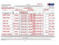
Exhibit 1 characterizes the 11 foundries and die casters visited. During each plant visit, the<br />
assessment team evaluated whether the recommendations and technologies listed above had been<br />
incorporated into the facilities’ daily operations. In cases where these technologies had not been<br />
incorporated, the team made suggestions as to how the recommendations could reduce a<br />
facility’s energy consumption and improve its financial performance. The assessment team also<br />
informed each facility about the tools and services <strong>of</strong>fered by the ITP <strong>Best</strong><strong>Practices</strong> subprogram,<br />
in particular how those tools and services could help the facility to analyze and reduce its energy<br />
consumption.<br />
Alloy Type Molding Process<br />
Exhibit 1: Characterization <strong>of</strong> Participating Facilities<br />
Melting<br />
Method<br />
Monthly Melt<br />
(tons)<br />
Assessment-<br />
Sponsoring<br />
Society*<br />
Steel No-Bake Sand Electric Arc 3,000 SFSA<br />
Steel No-Bake Sand Electric Arc 1,000 SFSA<br />
Aluminum (300 Series)<br />
and Zinc<br />
Die <strong>Casting</strong> Reverberatory 50 NADCA<br />
Aluminum (A380 &A383) Die <strong>Casting</strong> Reverberatory 1,000 NADCA<br />
Copper<br />
Permanent Mold; No-Bake<br />
Sand<br />
Reverberatory 125 AFS<br />
Aluminum (300 Series) Lost Foam Reverberatory AFS<br />
Iron (Gray, Ductile) Green Sand Cupola AFS<br />
Iron (Gray and Ductile) Green Sand Cupola 4,200 AFS<br />
Aluminum (300 Series) Lost Foam Reverberatory 150 AFS<br />
Aluminum (30 different<br />
alloys)<br />
Green Sand, Permanent<br />
Mold, Die <strong>Casting</strong><br />
Crucible 425 AFS<br />
Aluminum Lost Foam with Pressure Reverberatory 1,700 AFS<br />
* SFSA: Steel Founders’ Society <strong>of</strong> America<br />
NADCA: North American Die <strong>Casting</strong> Association<br />
AFS: American Foundry Society<br />
For more details on the assessment methodology, see Section 4 on page 16.<br />
3
1.3 Report Organization<br />
This report summarizes the observations and recommendations made throughout the 11 plant<br />
assessments. It includes an overview <strong>of</strong> the metal casting industry, followed by an overview and<br />
analysis <strong>of</strong> the ITP <strong>Best</strong> <strong>Practices</strong> tools and services that are applicable to the industry. It<br />
highlights how these tools and services can be accessed and used by metal casters. The report<br />
documents general recommendations that were commonly made by the assessment team<br />
throughout the project, and provides a case study <strong>of</strong> each facility visited (see Appendix A). The<br />
case studies are categorized by the type <strong>of</strong> casting operation employed: steel, die casting, lost<br />
foam, iron, and copper/aluminum foundries. Each case study provides a plant pr<strong>of</strong>ile with details<br />
about its operation, general observations, and assessment <strong>of</strong> implemented ITP research projects.<br />
The case studies highlight the energy savings and financial paybacks that these plants received<br />
by incorporating R&D project results into their daily operations. For brevity, “<strong>Metal</strong> <strong>Casting</strong><br />
R&D” refers to the ITP/CMC research collaborations throughout the remainder <strong>of</strong> this report.<br />
4
2. <strong>Metal</strong> <strong>Casting</strong> Industry Overview<br />
The metal casting industry produces both simple and complex parts that meet a wide variety <strong>of</strong><br />
manufacturing needs. Nearly all manufactured goods contain one or more cast components, with<br />
major end uses being motor vehicles, defense equipment, power generation equipment, industrial<br />
machinery, construction materials, pipes and fittings, oil field machinery, farm equipment,<br />
railroad equipment, and other products vital to our economic growth and national security.<br />
Although the industry utilizes many different processes and metals for casting, the basic metal<br />
casting process involves pouring or injecting molten metal into a mold or die containing a cavity<br />
<strong>of</strong> the desired shape. The most common process used for casting is green sand molding,<br />
accounting for approximately 60% <strong>of</strong> castings produced. Other methods include die casting,<br />
permanent mold casting, investment casting, lost foam casting, squeeze casting, and shell<br />
molding. Gray and ductile irons continue to comprise the greatest weight <strong>of</strong> casting shipments,<br />
followed by aluminum, steel, and copper. In addition, viable new markets are opening for<br />
magnesium, titanium, and other nonferrous alloys. For example, forecasters predict that<br />
magnesium shipments in the automotive sector will nearly double by 2008. 15<br />
Markets for both ferrous and non-ferrous castings are increasingly competitive, with casting<br />
customers placing greater emphasis on securing high-quality, light-weight, high-strength<br />
products at lower prices. Thus, the casting industry must continuously evolve and improve to<br />
remain competitive in today’s market place.<br />
Energy Use Exhibit 2: <strong>Metal</strong> <strong>Casting</strong> Industry Distribution<br />
<strong>of</strong> Energy Sources<br />
The metal casting industry consumed 257 trillion<br />
Btu in 2002, 16 with 165 trillion Btu accounted for<br />
by metal casters categorized under NAICS 3315 *<br />
and 92 trillion Btu by captive foundries. † This<br />
represents more than a 21% decrease in the<br />
industry’s energy consumption as compared to<br />
328 trillion Btu consumed in 1998. 17 This decline<br />
reflects a 26.6% reduction in the total shipment<br />
tonnage from 1998 to 2002, which occurred when<br />
a number <strong>of</strong> foundries went out <strong>of</strong> business.<br />
The metal casting industry utilizes a variety <strong>of</strong><br />
fuels and electricity to meet its energy needs<br />
(Exhibit 2). In 2002, 46% <strong>of</strong> the industry’s energy<br />
was provided by natural gas and 33% by<br />
electricity. Coke provided 17% <strong>of</strong> the industry’s<br />
Electrcity<br />
33%<br />
Coke &<br />
Breeze<br />
17%<br />
Other<br />
4%<br />
Natural<br />
Gas<br />
46%<br />
Source: U.S. Department <strong>of</strong> Energy, Energy Information<br />
Administration, 2002 Manufacturers Energy Consumption,<br />
Table N1.2 “First Use <strong>of</strong> Energy for All Purposes,” NAICS<br />
3315; 331511; 331521; 331524<br />
* NAICS 3315 Foundries: This industry group comprises establishments primarily engaged in pouring molten<br />
metal into molds or dies to form castings. Establishments making castings and further manufacturing, such as<br />
machining or assembling, a specific manufactured product are classified in the industry <strong>of</strong> the finished product.<br />
† See Glossary (page 91)<br />
5
energy needs, primarily to the large iron foundries that utilize the coke both as a fuel for melting<br />
and as a source <strong>of</strong> carbon. 18<br />
The major energy-consuming processes in<br />
metal casting include melting metal, core<br />
making, heat treating, and post-casting<br />
operations. Exhibit 3 illustrates the<br />
distribution <strong>of</strong> the process energy cost<br />
within these operations, with melting<br />
representing 55% <strong>of</strong> the total. 19 The<br />
industry spent $1.4 billion in 2004 on<br />
purchased fuels and electricity, equaling<br />
approximately 11% <strong>of</strong> the material costs<br />
and 5% <strong>of</strong> the value <strong>of</strong> the shipments.<br />
Energy costs were highest in ferrous<br />
foundries where they averaged 12% <strong>of</strong><br />
material costs and 5% <strong>of</strong> the value <strong>of</strong><br />
shipments. They were lowest in<br />
nonferrous foundries that were not related<br />
to aluminum where they averaged 8% <strong>of</strong><br />
the material costs and 3% <strong>of</strong> the value <strong>of</strong><br />
shipments. 20<br />
Market Overview<br />
Exhibit 3: Distribution <strong>of</strong> <strong>Casting</strong> Process Energy<br />
Costs<br />
Melting<br />
55%<br />
Heat<br />
Treatment<br />
6%<br />
Other<br />
12%<br />
Moldmaking<br />
12%<br />
Coremakin<br />
g<br />
8%<br />
Post<br />
<strong>Casting</strong><br />
7%<br />
Source: U.S. Department <strong>of</strong> Energy, Office <strong>of</strong> Industrial<br />
Technologies, <strong>Metal</strong> <strong>Casting</strong> Industry <strong>of</strong> the Future, Energy<br />
and Environmental Pr<strong>of</strong>ile <strong>of</strong> the U.S. <strong>Metal</strong> <strong>Casting</strong> Industry,<br />
Washington DC 1999. pg. 10/<br />
In 2004, there were approximately 2,480 metal casting facilities 21 located throughout the United<br />
States, employing approximately 161,000 people. 22 Although the industry is widely dispersed<br />
throughout, six states account for over 60% <strong>of</strong> all shipments: Alabama (14.3%), Ohio (12.8%),<br />
Indiana (11.1%), Wisconsin (11.1%), Illinois (7.3%), and Michigan (7.2%). 23 A majority <strong>of</strong><br />
metal casters are small businesses, with 80% employing fewer than 100 people, 14% between<br />
100 and 250 people, and 6% more than 250 people. 24 These small businesses are vital to the<br />
economic well being <strong>of</strong> their local communities.<br />
The metal casting industry has declined significantly since the early 1980s. In 1982, there were<br />
4,100 metal casters in the U.S. with a capacity <strong>of</strong> 23 million tons per year output. The number <strong>of</strong><br />
facilities has since dropped to approximately 2,380 in 2005. A substantial part <strong>of</strong> the decline in<br />
the number <strong>of</strong> facilities is due to the trend <strong>of</strong> consolidation <strong>of</strong> smaller ownerships. Fewer and<br />
larger facilities are starting to produce and ship a majority <strong>of</strong> the tonnage. During the period<br />
1982 to 2004, the capacity <strong>of</strong> the industry declined by 22.3%, while the number <strong>of</strong> metal casters<br />
decreased by 40%. 25<br />
6
3. ITP-Industry Partnership Efforts: Energy Efficiency and <strong>Best</strong><br />
<strong>Practices</strong><br />
Everyday tasks such as turning on a light, starting a car, or using a computer would not have<br />
been possible without metal casting. The metal casting industry has been integral to U.S. growth<br />
and has helped the U.S. become the world benchmark in fields such as manufacturing, science,<br />
medicine, and aerospace. The industry is diverse, employing a variety <strong>of</strong> casting processes and<br />
alloys. Since the majority <strong>of</strong> metal casters are small businesses, they lack the resources to<br />
perform high-risk, high-impact research on their own. Instead, they participate in research<br />
consortia and public-private partnerships. These collaborations are proving to be successful<br />
methods for performing research for the industry overall.<br />
The <strong>Metal</strong> <strong>Casting</strong> R&D initiative supports these partnerships by providing cost-shared R&D<br />
funding to improve the energy intensity <strong>of</strong> the metal casting industry. These partnerships are<br />
encouraged by ITP <strong>Metal</strong> <strong>Casting</strong> in collaboration with the CMC. The ITP <strong>Metal</strong> <strong>Casting</strong><br />
portfolio emphasizes university-based research, tapping the technical and knowledge resource <strong>of</strong><br />
our nation’s educational institutions and encouraging young students to enter the industry.<br />
Furthermore, the partnership encourages strong industry involvement to ensure direct application<br />
<strong>of</strong> research results and provides evidence as to the importance <strong>of</strong> cost-shared research<br />
partnerships.<br />
ITP also provides a variety <strong>of</strong> free s<strong>of</strong>tware tools and services through its <strong>Best</strong><strong>Practices</strong> initiative<br />
to help metal casters reduce their energy consumption within the near term at little or no cost.<br />
<strong>Metal</strong> casters can use these tools and services to assess their process heating operations (melting,<br />
holding, and heat treatment), compressed air systems, motor systems, and other operations to<br />
identify energy-saving opportunities. These tools and services have a proven track record <strong>of</strong><br />
helping metal casters identify no- and low-cost practices, retr<strong>of</strong>its, and upgrades to existing<br />
processes to save energy and money.<br />
The ITP-funded energy efficiency R&D technologies and <strong>Best</strong><strong>Practices</strong> tools and services<br />
beneficial to metal casters are described below.<br />
3.1 R&D <strong>of</strong> Energy-Efficient Technologies<br />
The <strong>Metal</strong> <strong>Casting</strong> R&D strategy is designed to encourage government-industry partnership in<br />
the energy-intensive metal casting industry. This strategy fostered industry partnerships, such as<br />
CMC, and created the driving force for the industry to develop long-term visions and roadmaps.<br />
The vision documents assist in developing goals for the future <strong>of</strong> the casting industry, while<br />
roadmaps provide an outline <strong>of</strong> the R&D needed to achieve the vision goals. The ITP <strong>Metal</strong><br />
<strong>Casting</strong> Vision and Roadmap documents, along with in-depth analysis <strong>of</strong> energy use in the<br />
industry, form the basis for open and competitive solicitations for pre-competitive R&D that<br />
addresses both the energy efficiency goals outlined in the National Energy Policy, as well as<br />
industry research priorities.<br />
7
As a result <strong>of</strong> this strategy, ITP has provided over $50 million in support <strong>of</strong> metal casting<br />
research, with an additional $60+ million provided by industry cost sharing since the portfolio’s<br />
inception in 1990. This funding has supported projects that have developed computer-based<br />
modeling tools and advanced sensors, provided methods for reducing machining requirements,<br />
and led to a greater understanding <strong>of</strong> material properties and performance. The funding also has<br />
accelerated innovative casting processes, such as lost foam, which has been implemented at large<br />
automotive and marine equipment companies as well as in smaller specialty casting shops.<br />
Currently, the <strong>Metal</strong> <strong>Casting</strong> R&D portfolio is divided into two categories: Advanced Melting<br />
and Innovative <strong>Casting</strong>. Research in the Advanced Melting category is developing new melting<br />
practices and/or new design methodologies that will improve the energy efficiency <strong>of</strong> melting<br />
and save costs for metal casters. Research in this area is improving melt efficiency, reducing<br />
metal transfer heat loss, reducing revert, and improving mold yield. The Innovative <strong>Casting</strong><br />
research category consists <strong>of</strong> projects that advance energy-efficient casting processes and<br />
practices to increase mold yield and reduce scrap. The projects in this area are developing<br />
accurate simulation tools; enhancing the ability to produce thin-wall, high-performance castings;<br />
producing real-time sensors and controls; making improvements in rapid prototyping; and<br />
expanding the knowledge base <strong>of</strong> various material properties and performances.<br />
3.2 ITP <strong>Best</strong> <strong>Practices</strong><br />
Increasing the energy efficiency <strong>of</strong> the metal casting industry is a long-term challenge, but with<br />
the tools and resources <strong>of</strong> ITP’s <strong>Best</strong><strong>Practices</strong> initiative, metal casters can start saving today.<br />
<strong>Best</strong><strong>Practices</strong> works with the metal casting industry and other industrial sectors to implement<br />
energy management practices. The program provides metal casters with a number <strong>of</strong> s<strong>of</strong>tware<br />
tools that plant personnel can use to analyze process heating as well as compressed air and motor<br />
systems, using plant-specific data to identify energy-saving opportunities. These tools can be<br />
downloaded for free from the ITP <strong>Best</strong><strong>Practices</strong> s<strong>of</strong>tware website<br />
(http://www1.eere.energy.gov/industry/bestpractices/s<strong>of</strong>tware.html). Furthermore, DOE stresses<br />
training on these tools since using them requires a thorough understanding <strong>of</strong> system dynamics.<br />
Qualified specialists <strong>of</strong>fer such training and can be located through the <strong>Best</strong><strong>Practices</strong> training<br />
website (http://www1.eere.energy.gov/industry/bestpractices/training.html).<br />
ITP <strong>Best</strong><strong>Practices</strong> also <strong>of</strong>fers several services whereby a team <strong>of</strong> students or energy pr<strong>of</strong>essionals<br />
performs plant assessments to assist metal casters in identifying energy-saving and process<br />
improvement opportunities. These tools and services have a proven track record <strong>of</strong> helping metal<br />
casters to increase energy efficiency and reduce costs. However, during this project, none <strong>of</strong> the<br />
facilities that underwent assessments were aware <strong>of</strong> these free tools and services.<br />
Following is a description <strong>of</strong> the major <strong>Best</strong><strong>Practices</strong> tools and services beneficial to metal<br />
casters:<br />
1. Process Heating Assessment and Survey Tool (PHAST)<br />
Melting and heat treatment operations in the metal casting industry account for 55% and 6%,<br />
respectively, <strong>of</strong> the process energy cost. 26 The thermal efficiency <strong>of</strong> individual components<br />
8
within an overall process heating system can vary significantly. Exhibit 4 compares the<br />
efficiency and the melt loss <strong>of</strong> the various types <strong>of</strong> furnaces the industry employs. As the Exhibit<br />
reveals, the efficiency <strong>of</strong> melting operations can vary from 7% (gas crucible, lower end) to 76%<br />
(induction, aluminum, upper end). These widely varying thermal efficiencies combined with<br />
high energy costs imply that casters should be able to identify many opportunities to improve<br />
furnace operations and thus generate significant energy (and cost) savings.<br />
Exhibit 4: Efficiency and Melt Loss for Different Die <strong>Casting</strong> Furnaces<br />
Melting Furnace Common Use Melt Loss Thermal Efficiency<br />
Cupola Iron 3-12% 40-50%<br />
Electric Arc Steel 5-8% 35-45%<br />
Immersion Zinc N/A 63-67%<br />
Electric Reverberatory<br />
Aluminum<br />
Zinc<br />
1-2%<br />
2-3%<br />
59-76%<br />
59-76%<br />
Gas Crucible<br />
Aluminum<br />
Magnesium<br />
4-6%<br />
4-6%<br />
7-19%<br />
7-19%<br />
Gas Reverberatory<br />
Aluminum<br />
Zinc<br />
3-5%<br />
4-7%<br />
30-45%<br />
32-40%<br />
Gas Stack Melter Aluminum 1-2% 40-45%<br />
Aluminum 0.75-1.25% 59-76%<br />
Copper-Base 2-3% 50-70%<br />
Induction<br />
Magnesium 2-3% 59-76%<br />
Iron 1-2% 50-70%<br />
Steel 2-3% 50-70%<br />
Source: Schwam D., Wallace J.F. and Wannasin J. “Energy Efficiency <strong>of</strong> Aluminum Melting in Die <strong>Casting</strong> Operations”, CastExpo,<br />
St. Louis, April 2005, Presentation T-072.<br />
The ITP <strong>Best</strong><strong>Practices</strong> portfolio <strong>of</strong>fers the Process Heating Assessment and Survey Tool<br />
(PHAST), a s<strong>of</strong>tware application that can aid metal casters in identifying opportunities for saving<br />
energy in process heating equipment such as melting furnaces, heat treatment furnaces, and<br />
holding furnaces. PHAST provides plant personnel with the tools to survey furnaces and to<br />
produce a report that identifies ways to increase the energy efficiency <strong>of</strong> individual pieces <strong>of</strong><br />
equipment throughout the entire heating process. <strong>Metal</strong> casters can assess equipment<br />
performance under varying operating conditions by changing the input parameter values used by<br />
PHAST.<br />
The PHAST application <strong>of</strong>fers three major benefits to metal casters:<br />
• Focuses Improvements on Energy-Intensive Equipment – Using the metal caster’s<br />
specific heat input and furnace operating data, the application reports the quantity and<br />
cost <strong>of</strong> fuel and electricity that each piece <strong>of</strong> equipment uses annually.<br />
• Calculates Potential Energy Savings – The application assesses energy-saving<br />
opportunities by comparing the performance <strong>of</strong> individual pieces <strong>of</strong> equipment under<br />
various operating conditions with that <strong>of</strong> a wide variety <strong>of</strong> retr<strong>of</strong>it technologies.<br />
• Identifies Energy Waste – PHAST evaluates all areas in which energy is used, lost, or<br />
wasted and constructs a detailed heat balance report for melting, holding, and heat<br />
treatment furnaces.<br />
9
All <strong>of</strong> the facilities that participated in this effort can benefit from PHAST and should have some<br />
<strong>of</strong> their staff trained on its use. The assessment team observed a number <strong>of</strong> obvious energy waste<br />
sources in each facility’s melting operation, including a lack <strong>of</strong> furnace coverings, improperly<br />
sealed containers, and excessive refractory wear. Utilizing PHAST will highlight possible<br />
adjustments plants can make to and optimize their process heating systems, potentially saving<br />
thousands <strong>of</strong> dollars annually in energy costs.<br />
The economic implications <strong>of</strong> process energy loss are<br />
substantial. Heat losses from uncovered furnaces and<br />
furnace sidewalls can be significant, costing the metal<br />
casters millions in unnecessarily high-energy bills.<br />
According to AFS, radiant heat loss from a molten<br />
aluminum surface can be sizeable, as illustrated in<br />
Exhibit 5. The optimal combination <strong>of</strong> refractory and<br />
insulation can reduce these losses and save metal<br />
casters considerable money. When one takes into<br />
account the furnace efficiency factor, which is as low as<br />
8-10% for a crucible furnace, the true cost <strong>of</strong> this heat<br />
2<br />
loss equates with 66,000 Btu/hr/ft . Thus, even<br />
assuming an electric furnace efficiency <strong>of</strong> perhaps 80%,<br />
the heat loss cost per square foot <strong>of</strong> uncovered molten<br />
aluminum is 8250 Btu/hr. Exhibit 6 summarizes the<br />
heat loss as a function <strong>of</strong> exterior surface temperature.<br />
Exhibit 7 provides the results <strong>of</strong> an illustrative<br />
calculation <strong>of</strong> the potential cost <strong>of</strong> energy loss based on<br />
a hypothetical gas-fired facility employing an<br />
electrically heated furnace.<br />
Exterior Surface<br />
Temperature (ºF)<br />
Exhibit 7: Examples <strong>of</strong> Potential Cost <strong>of</strong> Energy Loss<br />
Heat Loss<br />
(Btu/hr/ft 2 )<br />
Annual Cost for<br />
Gas-Fired Furnace*<br />
(per ft 2 )<br />
Exhibit 5: Radiant Heat Loss from<br />
Molten Aluminum Surface<br />
Aluminum Heat Loss<br />
Temperature (ºF) (Btu/hr/ft 2 )<br />
1,300 6,600<br />
1,400 9,300<br />
Source: AFS, as presented in Cast <strong>Metal</strong>s Institute<br />
course on Aluminum<br />
Exhibit 6: Heat Loss from an Exterior<br />
Furnace Surface<br />
Exterior Surface Heat Loss<br />
Temperature (ºF) (Btu/hr/ft 2 )<br />
212 284<br />
279 494<br />
471 1,046<br />
Source: Industrial Heating, November 2006, Page 36<br />
Annual Cost for<br />
Electrical Furnace**<br />
(per ft 2 )<br />
Energy Loss from Furnace Shell Surface<br />
212 284 $41 $63<br />
279 494 $72 $110<br />
411 1046 $152 $233<br />
Energy Loss from Uncovered Molten Aluminum Surface<br />
1300 6600 $957 $1472<br />
1400 9300 $1348 $2074<br />
Assumptions:<br />
* Natural gas costs – $10.00/million Btu; Operating hours – 8,700 hrs/yr; and Furnace efficiency – 60%<br />
** Electrical energy costs – $.07/Kwh; Operating hours – 8,700 hrs/yr; and Furnace efficiency – 80%<br />
2. AirMaster+<br />
The metal casting industry uses large amounts <strong>of</strong> compressed air for powering tools to perform a<br />
variety <strong>of</strong> tasks, including blowing resin coated sand into core boxes and green sand into copes<br />
and drags, pneumatically transporting sand, operating pneumatic cylinders and molding<br />
10
machines, spraying die lubricant, and blowing loose flash from trim equipment. Compressed air<br />
use is higher in typical sand foundries than in die casting operations. The compressed air<br />
pressure at a foundry ranges from 95-110 pounds per square inch (psi). In most cases,<br />
temperature control is only necessary to ensure that the dew point <strong>of</strong> the compressed air is kept<br />
low enough so that condensation does not collect in the line. However, some core-making<br />
processes require air at a - 40° F dew point to prevent chemical reaction between the resin and<br />
the moisture in the sand and air. 27<br />
Improving compressed air systems <strong>of</strong>fers an opportunity for metal casters to reduce their energy<br />
consumption and lower their costs. According to the Energy Use in Selected <strong>Metal</strong>casting<br />
Facilities – 2003 study, most compressed air system installations were the result <strong>of</strong> progressive<br />
growth needs and, thus, were <strong>of</strong>ten engineered poorly, were saturated with water, and exhibited<br />
numerous leaks. Furthermore, facilities <strong>of</strong>ten misapplied air in a variety <strong>of</strong> situations and<br />
selected air driers and other compressed air components based on initial capital cost rather than<br />
functionality, leading to poor operating efficiency.<br />
AirMaster+, another free s<strong>of</strong>tware tool <strong>of</strong>fered by the ITP <strong>Best</strong><strong>Practices</strong> portfolio, can help<br />
casters identify energy-saving opportunities in compressed air systems throughout the casting<br />
operation. Using plant-specific data, the tool assesses the compressed air systems and evaluates<br />
operational costs for various equipment configurations and system pr<strong>of</strong>iles. The tool estimates<br />
savings based on potential energy efficiency improvements and calculates the estimated payback<br />
periods.<br />
AirMaster+ evaluates the energy-savings potential based on reduced air leaks, improved end-use<br />
efficiency, reduced system pressure, the use <strong>of</strong> unloading controls, adjusted cascading set points,<br />
the use <strong>of</strong> automatic sequencers, reduced run time, and the addition <strong>of</strong> a primary receiver. The<br />
tool includes a database <strong>of</strong> generic or industry-standard compressor specifications and creates an<br />
inventory specific to the individual metal caster’s air system. Based on user-provided data, the<br />
tool simulates existing and modified compressed air system operations. It can model part-load<br />
system operations for an unlimited number <strong>of</strong> rotary screw, reciprocating, and centrifugal air<br />
compressors operating simultaneously with independent control strategies and schedules. The<br />
application also develops 24-hour metered airflow or power load pr<strong>of</strong>iles for each compressor,<br />
calculates lifecycle costs based on inputs <strong>of</strong> seasonal electric energy and demand charges, and<br />
tracks maintenance history for system components.<br />
In 2002, a foundry located in California that specializes in centrifugal casting implemented the<br />
AIRMaster+ tool in assessing its compressed air systems. Two rotary screw compressors served<br />
the facility: a 100-horsepower (hp) unit and a 50-hp unit. Results from the analysis enabled the<br />
facility to replace the 100-hp and 50-hp compressor with a new 50-hp compressor and upgrade<br />
the compressor controls to increase the system’s efficiency. The foundry then used the old 50-hp<br />
unit as a back up. Implementing the recommendations allowed the foundry to reduce its<br />
compressor capacity by 50%, resulting in annual compressed air energy savings <strong>of</strong> 242,000 kWh<br />
and an annual maintenance cost savings <strong>of</strong> $24,200. The implementation required the foundry to<br />
invest $38,000; however, the plant received a $10,000 incentive payment from the California<br />
Public Utilities Commission, reducing the total cost for the investment to $28,000 and its<br />
payback period for the foundry to 14 months.<br />
11
A number <strong>of</strong> the facilities visited during this analysis could benefit from performing a detailed<br />
compressed air analysis <strong>of</strong> their operation using AirMaster+. The assessment team found that<br />
these plants had numerous air leaks, misapplications <strong>of</strong> air, and at times poorly engineered<br />
systems. Use <strong>of</strong> this tool helps metal casters optimize their compressed air systems and<br />
determine ways to reduce the total amount <strong>of</strong> compressed air required.<br />
3. MotorMaster+<br />
Motor-driven equipment plays an essential role and is a major expense in the metal casting<br />
industry. Whether a metal caster should repair or replace motors requires a thorough knowledge<br />
<strong>of</strong> efficiencies, maintenance histories, and costs. DOE’s free MotorMaster+ s<strong>of</strong>tware tool<br />
analyzes motor and motor system efficiency to help in making these decisions.<br />
MotorMaster+ tool identifies inefficient or oversized motors at metal casting facilities and<br />
computes the energy savings associated with replacing them with more energy-efficient or<br />
appropriately sized models. In addition to facilitating repair and purchase decisions, the tool<br />
<strong>of</strong>fers inventory management, maintenance logging, lifecycle costing, conservation analysis,<br />
savings evaluation, energy accounting, and environmental reporting. This suite <strong>of</strong> features can<br />
help metal casters comprehensively manage their electric motor systems.<br />
The utility <strong>of</strong> MotorMaster+ was demonstrated at a major facility in Indiana that, based on<br />
MotorMaster+ analysis, replaced 125 motors with high-efficiency motors and saved $80,000 per<br />
year. The application also specified high-efficiency motors for new equipment purchases at the<br />
facility, yielding another $128,000 in annual savings.<br />
4. Industrial Assessment Centers<br />
Industrial Assessment Centers, or IACs, are DOE resources that <strong>of</strong>fer free technical assistance to<br />
metal casters (Exhibit 9). To date, the IACs have performed more than 350 assessments at metal<br />
casting and die casting facilities across the country. A team <strong>of</strong> engineering faculty and students<br />
from one <strong>of</strong> more than 26 participating universities perform these assessments. The universitybased<br />
teams conduct a one-day site visit to a subject plant, where students are equipped with data<br />
loggers to analyze the entire plant’s operation, including the compressed air systems, furnaces,<br />
molten metal handling, and lighting.<br />
12
Exhibit 9: Nationwide Locations <strong>of</strong> the IACs<br />
Once an assessment is completed, the IAC team provides a detailed report <strong>of</strong> its analysis,<br />
findings, and recommendations to the plant within 60 days. On average, the implementation <strong>of</strong><br />
actions recommended by the IAC results in an annual savings <strong>of</strong> $55,000 per plant. Exhibit 10<br />
lists some <strong>of</strong> the recommendations made by the IACs to metal casters, their average<br />
implementation costs, and their resultant annual savings. To learn more about these and the<br />
Center locations, visit http://iac.rutgers.edu/database * .<br />
Facility<br />
Type<br />
Gray and<br />
Ductile Iron<br />
Foundry<br />
Steel<br />
Investment<br />
Foundry<br />
Yearly<br />
Energy<br />
Costs<br />
$1,694,719<br />
$2,171,872<br />
Exhibit 10: Recent IAC Recommendations to <strong>Metal</strong> Casters<br />
Recommendation<br />
Cost to<br />
Implement<br />
($)<br />
Annual<br />
Savings<br />
($)<br />
Payback<br />
Period<br />
(Yr)<br />
Automatic Grinding Stations $250,000 $269,280 0.9<br />
Replace No. 2 Fuel Oil Furnace with an Electric<br />
Furnace<br />
$40,000 $55,434 0.7<br />
Improve and Maintain the Insulating Dome Lids<br />
on Furnaces<br />
$10,000 $52,852 0.2<br />
Repair Leaks in Compressed Air Lines $2,484 $19,606 0.1<br />
Install an Air/Air Heat Exchanger to Retain<br />
Exhaust Air Heat<br />
$150,000 $35,862 4.2<br />
Reduce Charging Time by Use <strong>of</strong> Gated<br />
Feeders<br />
$50,000 $22,098 2.3<br />
Replace Drive Belts on Motors with Energy<br />
Efficient Cog Belts<br />
$840 $864 1.0<br />
Schedule Induction Melters to Reduce Peak<br />
Demand<br />
$20,000 $41,580 0.5<br />
Convert Boiler Clave to Steam Heat $15,605 $13,555 1.2<br />
Preheat Burnout Oven Combustion Air $9,830 $5,980 1.6<br />
Retr<strong>of</strong>it Lighting Fixtures to High Efficiency<br />
Bulbs<br />
$12,543 $4,977 2.5<br />
Turn Off Furnace Blowers During Cool Down $1,039 $3,918 0.3<br />
Repair Compressed Air Leaks $600 $3,228 0.2<br />
* The IAC database contains hundreds <strong>of</strong> assessments where hundreds <strong>of</strong> recommendations from previous<br />
assessments are stored. Exhibit 10 displays a select few <strong>of</strong> those recommendations.<br />
13
Steel<br />
Foundry<br />
Aluminum<br />
Foundry<br />
Aluminum<br />
Die <strong>Casting</strong><br />
Nonferrous<br />
Die-<br />
<strong>Casting</strong>s,<br />
Except<br />
Aluminum<br />
Copper<br />
Foundry<br />
Nonferrous<br />
Foundry<br />
$2,440,059<br />
$1,582,653<br />
$534,927<br />
$287,756<br />
124,803<br />
Insulate Condensation Tank $550 $910 0.6<br />
Reduce Compressed Air Leaks $779 $9,964 0.1<br />
Reduce Compressed Air Pressure $25 $2,291 0<br />
Install Screw Compressor $136,000 $58,932 2.3<br />
Install High Efficiency Lighting $0 $1,061 0<br />
Install Electronic Ballast and t-8 Lamps $8,950 $1,976 4.5<br />
Install Occupancy Sensors $2,261 $677 3.3<br />
Install High Efficiency Motors $1,356 $1,748 0.8<br />
Reduce Compressed Air Pressure $25 $1,405 0<br />
Reduce Compressed Air Leaks $474 $5,625 0.1<br />
Install High Efficiency Motors $866 $866 1.0<br />
Install Electronic Ballasts and T-8 $6,232 $2,387 2.6<br />
Install High Efficiency Lighting $3,807 $5,647 0.7<br />
Install Occupancy Sensors $1,729 $918 1.9<br />
Insulate Melt Furnace $12,275 $11,767 1.0<br />
Insulate Heat Treatment Furnaces $6,902 $8,410 0.8<br />
Insulate Ingot Preheat Box $198 $1,907 0.2<br />
Investigate the Possibility <strong>of</strong> Alternative Electric<br />
Rate Schedule<br />
$0 $12,973 0<br />
Install Economizers on the Existing Padmounted<br />
Units<br />
$2,400 $3,034 0.8<br />
Insulate the Gas Kilns $3,782 $7,575 0.5<br />
Implement A Regular Maintenance Program to<br />
Eliminate Air Leaks<br />
$535 $6,211 0.1<br />
Install Adequate Compressed Air Storage $3,690 $2,882 1.3<br />
Replace T12 Fluorescent Lighting with T8<br />
Fluorescent Lighting<br />
$5,444 $763 7.1<br />
Retr<strong>of</strong>it Exit Signs With LED Kits $745 $464 1.6<br />
Replace Mercury Vapor With <strong>Metal</strong> Halide $1,846 $550 3.4<br />
Install Compact Florescent Bulbs $540 $319 1.7<br />
Replace Existing Ballasts $3,402 $872 3.9<br />
High Efficient Motors $1,517 $599 2.5<br />
Install High Efficiency Fixtures $26,880 $7,681 3.5<br />
Reduces Paint Booth Operating Time $100 $3,393 0<br />
Insulate Molding Pots $1,300 $2,891 0.4<br />
Install Occupancy Sensors $1,000 $455 2.2<br />
Repair Air Leaks $600 $4,249 0.1<br />
Recover Exhaust Heat $6,000 $4,332 1.4<br />
Add Insulation to Side <strong>of</strong> Furnace $2,228 $1,824 1.3<br />
Add Insulated Furnace Cover $1,324 $3,029 0.4<br />
Install Waste Gas Evaporator $7,313 $9,120 0.8<br />
Reduce Compressed Air Leaks $30 $18,950 0<br />
Reduce Compressed Air Pressure $30 $294 0.1<br />
Install High Efficiency Lighting $3,755 $519 7.2<br />
Install High Efficiency Air Conditioners $8,550 $2,428 3.5<br />
Install High Efficiency Replacement Motors as<br />
Existing Motors Fail<br />
$89 $216 0.4<br />
Delamp Unnecessary Lighting $49 $209 0.2<br />
Use Synthetic Lubricants for Compressor $3,231 $420 7.7<br />
Plants that may be eligible for an IAC assessment include small- to medium-sized manufacturing<br />
plants falling under Standard Industrial Classification (SIC) Codes 20-39. The plant should be<br />
located within 150 miles <strong>of</strong> an IAC-participating university and have:<br />
• gross annual sales below $100 million,<br />
• fewer than 500 employees at the site,<br />
• an annual utility bill <strong>of</strong> more than $100,000 and less than $2 million, and<br />
• no in-house pr<strong>of</strong>essional staff to perform such an assessment.<br />
14
Both plant managers and students benefit from the IAC assessments. Students receive exposure<br />
and training in the areas <strong>of</strong> industrial assessment and management techniques for energy systems.<br />
IAC participation generates interest among these students in careers and opportunities in the<br />
metal casting industry, which is critical to maintaining a competitive edge in the global market.<br />
The IACs train more than 250 students each year.<br />
Rutgers University’s Center for Advanced Energy Systems (CAES) maintains a comprehensive<br />
database on more than 13,000 assessments conducted by the IACs and over 100,000<br />
recommendations made to date (http://iac.rutgers.edu/database).<br />
5. Save Energy Now<br />
Save Energy Now is an initiative that is part <strong>of</strong> a national campaign, “Easy Ways to Save<br />
Energy,” announced by the U.S. Secretary <strong>of</strong> Energy in 2005. The campaign aims to assist U.S.<br />
industrial and government entities in reducing energy use, to support achieving national goals for<br />
energy security, and to educate the public about simple but effective energy choices. Save<br />
Energy Now is helping industrial plants find effective ways to reduce energy use in steam and<br />
process heating systems so they can operate more efficiently and pr<strong>of</strong>itably. This initiative is also<br />
addressing energy-saving opportunities for compressed air, fan, motor, and pumping systems.<br />
Save Energy Now assistance is available to companies, states, utilities, and other industry<br />
groups. Thus, the U.S. metal casters can avail themselves <strong>of</strong> a service that involves energy<br />
savings assessment performed by a team <strong>of</strong> pr<strong>of</strong>essional energy efficiency experts for the<br />
nation’s large, energy-intensive plants. These large energy users are selected through a<br />
competitive solicitation process.<br />
The initiative also makes available phone consultations for technical assistance provided by<br />
experts at the <strong>EERE</strong> Information Center. The Center <strong>of</strong>fers numerous assistance activities, such<br />
as training, Web cast events, and workshops regarding the use <strong>of</strong> <strong>Best</strong><strong>Practices</strong> analysis tools and<br />
ways to improve energy efficiency and productivity throughout the plant.<br />
Finally, the initiative provides manufacturers with free access to its extensive portfolio <strong>of</strong> helpful<br />
information including tip sheets, case studies, and handbooks.<br />
Additional information about the Save Energy Now initiative and how companies can access its<br />
services is available at www.eere.energy.gov/industry/saveenergynow/.<br />
6. Other <strong>Best</strong><strong>Practices</strong> Services<br />
ITP’s <strong>Best</strong><strong>Practices</strong> initiative also <strong>of</strong>fers system-wide and component-specific training programs<br />
throughout the United States, as well as training on the <strong>Best</strong><strong>Practices</strong> s<strong>of</strong>tware tools available for<br />
a nominal fee. In addition, it makes available a wide spectrum <strong>of</strong> publications, ranging from<br />
articles on industrial energy management, industry sourcebooks, and case studies narrating real<br />
energy-saving success stories. These resources are available for free at ITP <strong>Best</strong><strong>Practices</strong> website,<br />
www.eere.energy.gov/industry/bestpractices.<br />
15
4. Methodology for Assessing Industrial <strong>Implementation</strong> <strong>of</strong> ITP<br />
Technologies and <strong>Best</strong><strong>Practices</strong> Tools<br />
The three metal casting societies that comprise the CMC (i.e., AFS, NADCA, and SFSA)<br />
initially nominated the metal casting facilities that participated in this project. The nominating<br />
society took the initial step to arrange site visits by contacting the key personnel and soliciting<br />
their participation. Once the society received confirmation <strong>of</strong> a company’s willingness to<br />
participate, the assessment team again contacted the key individual(s) at the facility to schedule<br />
the visit.<br />
The assessment team employed the same general methodology at each site visit. The key contact<br />
at the facility would assemble the appropriate facility personnel with whom the team would meet,<br />
which typically included a plant manager, plant engineer, energy manager, and technical staff<br />
member. A representative from NADCA, AFS, or SFSA usually accompanied the assessment<br />
team on the site visit so they could provide additional insight into implemented R&D results. The<br />
site visits would begin promptly in the morning with a face-to-face meeting <strong>of</strong> the assessment<br />
team and all necessary plant personnel. At this meeting, the assessment team would provide an<br />
overview <strong>of</strong> the assessment objectives and <strong>of</strong> the overall project. The assessment team would<br />
then provide an overview <strong>of</strong> the free tools and services <strong>of</strong>fered by ITP, followed by followed by<br />
a discussion <strong>of</strong> the implemented and non-implemented CMC and ITP <strong>Metal</strong> <strong>Casting</strong>-funded<br />
research that pertained to their facility. Facilities that the societies suggested tended to have<br />
participated in a number <strong>of</strong> past CMC and ITP-funded metal casting projects, and had<br />
implemented the results to some extent.<br />
As part <strong>of</strong> the overview <strong>of</strong> the free tools and services <strong>of</strong>fered by ITP, the assessment team<br />
focused on the <strong>Best</strong><strong>Practices</strong>’ MotorMaster+, AirMaster+, and PHAST tools which are felt to be<br />
the most relevant to the metal casting operations <strong>of</strong> all the <strong>Best</strong><strong>Practices</strong> tools. The assessment<br />
team distributed copies <strong>of</strong> the s<strong>of</strong>tware and descriptive fact sheets, and emphasized the need for<br />
training on the use <strong>of</strong> the tools. Also, the assessment team summarized the free services <strong>of</strong>fered<br />
by the IACs, provided a listing <strong>of</strong> the 10 most recent IAC assessments that were in the same<br />
NAICS code as the facility being visited, and supplied contact information for the nearest IAC in<br />
their region. Furthermore, facilities that met the size criterion were encouraged to apply for a<br />
Save Energy Now (SEN) assessment.<br />
Following the overview, the assessment team would then engage in dialogue with the facility<br />
team on the level <strong>of</strong> <strong>Best</strong><strong>Practices</strong> implementation that had occurred at the facility. Based on a<br />
descriptive list given to them on projects relevant to their operation, the plant personnel would<br />
discuss whether they had integrated relevant R&D results into their operations and would<br />
describe the benefits they had realized through such integration. If integration had not occurred,<br />
plant personnel would explain why. If a lack <strong>of</strong> familiarity with the project was the reason, the<br />
society representative would provide some detail on the R&D, the results obtained, and potential<br />
applicability <strong>of</strong> those results to the subject facility.<br />
After this initial meeting, the assessment team would then take a several-hour tour <strong>of</strong> the plant<br />
accompanied by plant personnel. The objectives <strong>of</strong> this tour were to observe which practices had<br />
16
een implemented and to evaluate the general “state-<strong>of</strong>-the-plant.” During this tour, the<br />
assessment team would note obvious wastes <strong>of</strong> energy, such as lack <strong>of</strong> furnace coverings,<br />
compressed air leaks, and unnecessary lighting. The tour was not intended to convey a thorough<br />
understanding <strong>of</strong> facility operations but to provide the team with an overview <strong>of</strong> the facility.<br />
After the tour, the assessment team and facility team reassembled to go over the observations<br />
made during the plant tour. At this meeting, the team requested from plant management specific<br />
metrics regarding research result implementation. These metrics generally centered around scrap<br />
rate reductions, yield rate improvement, and cost savings realized by the plant from best<br />
practices implementation. In addition, during this meeting, the assessment team provided a<br />
summary <strong>of</strong> comments regarding the tour and committed to addressing facility personnel<br />
requests regarding ITP tools and projects with which they were unfamiliar. This included<br />
locating relevant reports for plant personnel or sending information on how to apply for a SEN<br />
assessment.<br />
The assessment team concluded the plant visit by sending a letter recapping the site visit to the<br />
key contact at the plant. The letter presented a brief summary <strong>of</strong> issues observed during the plant<br />
tour that could help the plant become more efficient and competitive. These issues ranged from<br />
energy conservation to housekeeping. The letter also included a list <strong>of</strong> action items that each<br />
member <strong>of</strong> the assessment team and the facility team would address. Once the letter was sent, the<br />
assessment team followed up with plant personnel via telephone until the desired metrics were<br />
obtained or it was determined that the metrics could not be provided. No facilities were revisited<br />
to determine if there was any action that resulted directly from the facility assessment.<br />
17
5. Overall Assessment Observations<br />
Although the site visits uncovered some examples where <strong>Metal</strong> <strong>Casting</strong> R&D results had been<br />
adopted, in general implementation and quantification <strong>of</strong> research results was found to be poor.<br />
Therefore, a major focus <strong>of</strong> this project involved examining the reasons for the lack <strong>of</strong><br />
implementation <strong>of</strong> the beneficial results <strong>of</strong> the <strong>Metal</strong> <strong>Casting</strong> R&D projects. Many <strong>of</strong> those<br />
projects have been proven in both laboratoryand plant trials, yet many facilities do not take<br />
advantage <strong>of</strong> their beneficial findings. The following section provides a synopsis <strong>of</strong> general<br />
observations made by the assessment team that may have afected implementation. Appendix A<br />
provides detailed case studies <strong>of</strong> each facility assessed for industry “<strong>Best</strong> <strong>Practices</strong>” and<br />
identifies areas for their potential improvement.<br />
5.1 Need for a Champion<br />
During the 11 assessments conducted as part <strong>of</strong> this project, the assessment team observed a<br />
number <strong>of</strong> industry best practices implemented in the various facilities, yet also noted a number<br />
<strong>of</strong> areas that required attention and needed improvement. One factor that affected <strong>Best</strong> <strong>Practices</strong><br />
implementation was observed to be the presence or absence <strong>of</strong> a “champion” at the facility for a<br />
given technology or for energy efficiency in general. A champion, who understands the<br />
technology and the potential benefits <strong>of</strong> trying to successfully implement it even if the effort may<br />
fail, is vested in ensuring that the project is implemented to its fullest capability. In cases where<br />
there was a champion at the plant for a given energy efficiency improvement, it was<br />
implemented with great success.<br />
For example, at Steel Foundry-2 (page 52), the Foundry Manager <strong>of</strong> Technical Services has been<br />
an excellent champion for a variety <strong>of</strong> <strong>Metal</strong> <strong>Casting</strong> R&D projects and saw potential financial<br />
and productivity gains from them. The Manager specifically recognized the benefits that could<br />
be gained from implementing the shroud pouring process and determined that the potential<br />
payback outweighed the risk and inconvenience <strong>of</strong> the trial-and-error process needed to get the<br />
technology to function properly in his production line. Additionally, the Foundry Manager has<br />
been a proactive champion, not just waiting for a technology advancement to appear, but instead<br />
actively searching through resources to find solutions that he can implement. He attends the<br />
technical sessions <strong>of</strong>fered by SFSA and engages researchers on projects that he feels can be<br />
beneficial to his operation. He volunteers time and staff to test the research out in his facility.<br />
The assessment team found that when there was a lack <strong>of</strong> implementation or understanding at a<br />
facility, it was accompanied by the absence <strong>of</strong> a champion. Even very simple and low-cost<br />
solutions, such as covering a furnace or sealing a furnace door, were not implemented. In fact,<br />
throughout this project, numerous casters were found to have their furnaces uncovered, thus<br />
allowing heat to escape and dross to form. This action cost them in both wasted energy and<br />
wasted material costs. Champions can be created within a facility by instituting incentives and by<br />
assigning a lead or a team to take charge in reducing energy consumption.<br />
18
5.2 Reluctance in Investigation for Root Cause<br />
A commonly observed aspect during this analysis was that many foundries and die casters were<br />
not committed to determining the root cause <strong>of</strong> the imperfections in their products or in the<br />
facility used for their production. Due to the economic pressures <strong>of</strong> the competitive metal casting<br />
industry, many casters solely focus on shipping products fast rather than on minimizing number<br />
<strong>of</strong> imperfections. In general, the metal caster will incorporate the expense <strong>of</strong> the imperfections<br />
into their cost structure rather than exploring opportunities to reduce or eliminate these expenses.<br />
There is a willingness to accept high level <strong>of</strong> imperfections, which creates a culture <strong>of</strong> complying<br />
with mediocrity. While this phenomenon does not always occur throughout an entire plant, it was<br />
frequently observed in specific areas <strong>of</strong> a plant. One case that exemplified this phenomenon was<br />
the extremely high scrap rate on a particular part produced at Die <strong>Casting</strong> Facility-2 (page 42).<br />
This plant had an internal scrap rate <strong>of</strong> over 20% on a particular casting. Thus, in order to<br />
produce 100 good castings, the facility had to produce 125 castings overall. The facility had five<br />
die casting machines working round the clock to produce this casting, which meant that one<br />
machine each day was essentially dedicated to producing scrap castings. This part is a legacy<br />
part that was designed 10 to 15 years ago. Initially the facility had examined ways to reduce the<br />
scrap rate <strong>of</strong> this part. However, they abandoned searching for a permanent remedy after several<br />
failed efforts. Die <strong>Casting</strong> Facility-2 accepted the flawed process and instead incorporated the<br />
expense <strong>of</strong> this scrap rate into their cost <strong>of</strong> doing business. Eppich Technologies when visiting<br />
another die caster who had reduced its internal scrap rate from 35% to 25% noted a similar<br />
instance. Having achieved this drop, the facility was content with the improved performance and<br />
abandoned efforts for further scrap reduction. Thus, a 25% scrap level became acceptable. These<br />
examples are two extreme cases. Nonetheless, these types <strong>of</strong> practices will greatly jeopardize a<br />
plant’s ability to compete in the long run.<br />
Some facilities were found to seek solutions in some areas but ignore problems in others. For<br />
example, at Die <strong>Casting</strong> Facility-1 (page 36), management implemented a number <strong>of</strong> industry<br />
best practices and incorporated a number <strong>of</strong> <strong>Metal</strong> <strong>Casting</strong> R&D project results into their<br />
operation. The facility was at the cutting edge <strong>of</strong> implementing fatigue-resistant die materials due<br />
to their participation in critical plant trials performed by a university and funded by the <strong>Metal</strong><br />
<strong>Casting</strong> R&D portfolio. The facility widely publicized this effort and has become an advocate for<br />
the research results. Yet the facility tended to overlook some simple housekeeping improvements,<br />
such as ignoring the need to keep their furnace openings sealed. A significant amount <strong>of</strong><br />
hydraulic oil was observed on the floor and considerable heat was being lost through furnace<br />
openings. Preliminary calculations showed that the heat loss was approaching their pr<strong>of</strong>it <strong>of</strong><br />
approximately $1 million in sales. There seemed a willingness to accept these inefficiencies and<br />
factors within the melting department. However, in other departments, such as machining<br />
operations, housekeeping was exceptional. This shows the lack <strong>of</strong> departmental champions or<br />
commitment by plant management to hold all <strong>of</strong> the departments to a common standard.<br />
Committing to the investigation and elimination <strong>of</strong> root causes has improved product reliability,<br />
competitiveness, and the financial bottom line at Aluminum <strong>Casting</strong> Facility-1 (page 75). This<br />
facility participated in a research program, Improvements in Efficiency <strong>of</strong> Melting for Die<br />
<strong>Casting</strong>, conducted by a team from Case Western Reserve University with cost-share funding<br />
from <strong>Metal</strong> <strong>Casting</strong> R&D. During their site visit, the team from Case Western took metal<br />
19
samples and measurements from various points in the facility’s melting operation to check the<br />
metal quality. They found that the die casting dip wells contained four times the amount <strong>of</strong><br />
oxides as compared to the induction furnace. To increase product quality, these oxides needed to<br />
be eliminated prior to having the metal enter the die cavity. Initially the facility’s management<br />
thought that Case Western’s findings were a mistake or a misreading, and they enlisted a second<br />
opinion from an independent metal casting consulting firm. The results were identical to Case<br />
Western’s research findings. The consulting group recommended that the facility change from a<br />
double square-head degasser to a single circular-head degasser, which would virtually eliminate<br />
the oxides. Based on the two consistent observations, Aluminum <strong>Casting</strong> Facility-1 implemented<br />
this approach throughout its operation and it was endorsed by the highest level <strong>of</strong> management.<br />
Facilities that have sought to identify and address the root causes <strong>of</strong> their problems have<br />
experienced improvements in product quality and enjoyed an increase in pr<strong>of</strong>its. Die <strong>Casting</strong><br />
Facility-2 could save considerable energy and dollars by focusing on eliminating scrap on the<br />
legacy part but instead they simply internalized the scrap cost into their routine cost structure.<br />
Aluminum <strong>Casting</strong> Facility-1 questioned the oxide level initially yet did not discount those<br />
findings. They took the time and effort to determine the root cause, even enlisting a second<br />
opinion, so they could implement an effective solution. This approach at Aluminum <strong>Casting</strong><br />
Facility-1 was prevalent in all <strong>of</strong> their operations.<br />
5.3 Need for Business Case Analysis in Decision Making<br />
A common problem identified by the assessment team was a lack <strong>of</strong> knowledge on the part <strong>of</strong><br />
plant technical staff to build a business case for evaluating and implementing energysaving/productivity<br />
improvement processes and technologies. Furthermore, there was <strong>of</strong>ten a<br />
communication breakdown between the management and the technical staff, with the technical<br />
staff members considering themselves to be solely responsible for technical issues and not part <strong>of</strong><br />
the management process. This non-integrated approach to plant operation impedes achieving<br />
optimal working conditions at the facilities. Much <strong>of</strong> the lack <strong>of</strong> <strong>Metal</strong> <strong>Casting</strong> R&D project<br />
implementation has not been due to a lack <strong>of</strong> understanding the benefits <strong>of</strong> the research but rather<br />
the inability <strong>of</strong> many <strong>of</strong> the technically oriented personnel (e.g., metallurgists, engineers) to<br />
convey to management the short- and long-term paybacks on various energy efficiency<br />
technologies.<br />
Iron Foundry-2 (page 62) employs a highly trained technical staff to run the facility. It has some<br />
<strong>of</strong> the best metallurgists and young engineers in the industry and they understand the science<br />
behind many <strong>of</strong> the <strong>Metal</strong> <strong>Casting</strong> R&D projects. However, the staff has difficulty in<br />
communicating with upper management to explain the potential financial benefits that<br />
implementing the results <strong>of</strong> those projects could <strong>of</strong>fer. Even when implementation had occurred,<br />
the assessment team found that the facility was not tracking financial benefits and thus was<br />
unable to demonstrate the efficacy <strong>of</strong> technologies in improving facility performance. There is an<br />
urgent need at this facility to implement a model for such analyses, and to communicate their<br />
results to the decision-making management.<br />
This issue is not unique to Iron Foundry-2. It was prevalent throughout the project. Virtually<br />
every plant that participated in this effort was using computer modeling, both for solidification<br />
20
and flow analysis. However, when asked for specific data on the impact <strong>of</strong> these tools on their<br />
bottom line, no information was available. Every facility knew it had improved yield, scrap,<br />
and/or fatigue life, yet had no quantified estimate <strong>of</strong> the financial impact <strong>of</strong> these improvements.<br />
The energy savings, timeliness to market, and productivity cost savings were unknown.<br />
Therefore, it is difficult to communicate to corporate management the positive effect <strong>of</strong> these<br />
technologies and thus get their support for future projects. Building good business cases around<br />
these implemented projects is critical to surviving in today’s casting industry.<br />
Lost Foam Facility-1 (page 66) understands the importance <strong>of</strong> detailing the savings associated<br />
with the implementation <strong>of</strong> the <strong>Metal</strong> <strong>Casting</strong> R&D. This facility was able to provide metrics<br />
associated with the savings attributed to their two main casting lines: engines and blocks. They<br />
understood the impact <strong>of</strong> this research on their scrap and energy savings, including natural gas<br />
and electricity consumption. Management knew why research implementation was important and<br />
understood the benefits <strong>of</strong> supporting the Lost Foam Consortium.<br />
Steel Foundries-1 and -2 (pages 46 and 52) had detailed metrics associated with the economic<br />
importance <strong>of</strong> shroud pouring in their operations. They understood how it benefits their<br />
productivity and process flow throughout the plant by improving their pouring, machining, and<br />
finishing operations. They also recognized the impact that this process would have on customer<br />
satisfaction and the importance <strong>of</strong> this practice in retaining customers.<br />
An inability to develop a sound business case is also an issue in the industry when it comes to<br />
proposing a new project. Since most <strong>of</strong> the technical staff lacks the expertise to build a business<br />
case, it hinders research, the <strong>Best</strong><strong>Practices</strong> program, and new technology implementation. For<br />
example, almost all <strong>of</strong> the die casting, lost foam, and aluminum facilities in this project utilized<br />
reverberatory furnaces for their melting needs. These furnaces have a low efficiency (20 to 25%),<br />
high oxidation rate, and large space requirements. Yet the facilities use these furnaces because<br />
they do provide a large reservoir <strong>of</strong> molten metal that ensures a steady and reliable supply to the<br />
casting process. However, stack melters provide an alternative that can improve energy<br />
efficiency significantly. Stack melters have an efficiency <strong>of</strong> 40 to 50%, double that <strong>of</strong> a typical<br />
reverberatory furnace. These facilities need to build the business case for the suitability <strong>of</strong> the<br />
stack furnace, examining the cost <strong>of</strong> natural gas at today’s prices and estimated future prices<br />
rather than simply focusing on the up-front costs <strong>of</strong> the equipment and the historical prices <strong>of</strong><br />
natural gas.<br />
5.4 Lack <strong>of</strong> Awareness <strong>of</strong> Free ITP Tools and Services<br />
One <strong>of</strong> the objectives <strong>of</strong> this project was to gauge industry awareness <strong>of</strong> the free tools and<br />
services <strong>of</strong>fered by the ITP Technology Delivery subprogram. This subprogram provides no-cost<br />
assessments through the IAC and Save Energy Now initiatives, and also <strong>of</strong>fers free tools to<br />
analyze energy consumption in melting, compressed air, and motor systems. Very few <strong>of</strong> the<br />
participating facilities were aware <strong>of</strong> these free tools and services, indicating a need for a more<br />
comprehensive outreach and communication effort to disseminate information on these tools and<br />
services to the metal casting industry. Publishing articles in trade magazines such as Modern<br />
<strong>Casting</strong> or Die <strong>Casting</strong> Engineer and conducting training on the suite <strong>of</strong> <strong>Best</strong><strong>Practices</strong> tools at<br />
21
the <strong>Metal</strong>casting Congress and other industry meetings are means by which the industry can<br />
become familiar with the ITP resources.<br />
22
6. Solutions to Lack <strong>of</strong> R&D <strong>Implementation</strong><br />
Many <strong>of</strong> the common factors that hinder the implementation <strong>of</strong> research results and perpetuate<br />
the lack <strong>of</strong> awareness <strong>of</strong> free ITP resources available are not unique to the foundry industry.<br />
These are common problems that can be overcome both thorough education and outreach and by<br />
incorporating some fundamental changes in the management practices.<br />
6.1 Offering Incentives Program to Employees<br />
Organizational success at a metal casting facility depends upon its employees, and lack <strong>of</strong><br />
recognition can lead to poor morale and disengagement by employees. Effectively motivating<br />
employees can create champions within a foundry or die casting facility to seek out solutions for<br />
correcting efficiency issues. A meaningful employee recognition and incentive program can<br />
drive commitment to seek and implement necessary steps to improve operational efficiency and<br />
help the metal caster succeed in today’s competitive metal casting markets. Incentives should be<br />
provided to employees who seek out solutions to wasteful operations, such as air leaks and heat<br />
losses. This may involve simple solutions such as tagging and reporting air leaks to broader<br />
initiatives such as setting goals to reduce a facility’s overall air use by a certain percentage<br />
within a specified timeframe.<br />
Incentive programs should also encourage technical staff to undertake complex projects that will<br />
have a risk <strong>of</strong> failure yet <strong>of</strong>fer a high potential payback in both monetary and corporate<br />
sustainability terms. Facilities can implement incentive programs to challenge technical staff to<br />
improve the efficiency <strong>of</strong> or to eliminate a particular process. A good example to highlight this<br />
point is the lack <strong>of</strong> implementation <strong>of</strong> shroud pouring at Steel Foundry-1 (page 46). This facility<br />
participated in the initial casting trials and demonstrated to the casting industry the impact that<br />
shroud pouring would have on improving casting quality and pr<strong>of</strong>itability. However, when the<br />
facility installed a new molding line, they did not incorporate the proper height requirements to<br />
accommodate the shroud process. The company may have avoided this impediment had they<br />
provided an incentive for a champion to determine a solution to successfully integrating the<br />
shroud process.<br />
Employee incentives are a topic that many may consider old news, yet many companies still<br />
struggle to find ways to shift the behavior and attitude <strong>of</strong> their workers to increase productivity.<br />
Studies have shown that even the most simple incentive programs can be beneficial for both the<br />
employee and the corporation. Incentives can be simple, non-monetary rewards such as a better<br />
parking spot or an award, or they can take the form <strong>of</strong> a monetary bonus.<br />
The Power <strong>of</strong> Empowerment: What the Experts Say and 16 Actionable Case Studies by Bill<br />
Ginnodo (editor) shows how leading companies improve the performance <strong>of</strong> employees and<br />
managers—as well as customer satisfaction, costs, competitiveness and the bottom line—by<br />
giving individuals and teams the power to take action. 28 Empowering the foundry workers to<br />
take action and improve energy consumption may lead many metal casters to lower energy<br />
consumption and lower energy costs, thus improving their financial bottom line.<br />
A case to highlight the importance <strong>of</strong> incentive programs is Kingston Technology Company, Inc.,<br />
a world leader in independent memory. Founded in 1987 with a single product <strong>of</strong>fering, the<br />
23
single in-line memory module (SIMM), the company now <strong>of</strong>fers more than 2,000 memory<br />
products that support devices ranging from computers, servers, to MP3 players, and cell phones.<br />
In 2005, their sales exceeded $3.0 billion. 29<br />
Kingston has employed a strong incentives program for their employees, suppliers, and<br />
distributors that has benefited the staff and brought positive press to the company. In 1995,<br />
Kingston joined the billion-dollar club with sales exceeding $1.3 billion. In celebration <strong>of</strong> its<br />
achievement, the company took out ads in the Wall Street Journal, Orange County Register, and<br />
Los Angeles Times thanking the employees and identifying each by name. The company also ran<br />
ads thanking their suppliers and distributors in trade publications and the Wall Street Journal. 30<br />
Kingston recognized that this achievement would not have been possible without the hard work<br />
<strong>of</strong> their employees and everyone else in their supply and distribution chain. In December 1996,<br />
when S<strong>of</strong>tbank® Corporation <strong>of</strong> Japan acquired 80% <strong>of</strong> Kingston for a total <strong>of</strong> $1.5 billion, the<br />
company executives allocated $100 million for employee bonuses, thus tangibly illustrating to<br />
their employees their important contribution to the success <strong>of</strong> the company. This generous bonus<br />
has hurt neither the company’s bottom line nor its market share. In fact, Kingston announced in<br />
2005, total revenues <strong>of</strong> $1.475 billion, and has maintained 16.75% <strong>of</strong> the world’s market share<br />
for memory products, thus making them #1 in the world. 31<br />
While Kingston is an extreme example <strong>of</strong> the benefits realized by a corporation through an<br />
aggressive incentives program, it nevertheless demonstrates how success can derive from<br />
motivating employees. <strong>Metal</strong> casting companies could achieve significant savings by<br />
implementing best practices and eliminating waste. Foundries and die casters should seek to<br />
develop incentive programs that encourage their workers to reduce waste and energy, and<br />
increase productivity. Such programs will positively impact their financials bottom lines.<br />
6.2 Tracking Impact <strong>of</strong> R&D <strong>Implementation</strong><br />
All <strong>of</strong> the metal casters that participated in this analysis had implemented or evaluated results<br />
from several <strong>Metal</strong> <strong>Casting</strong> R&D projects. Many <strong>of</strong> the casters spoke <strong>of</strong> the benefits realized<br />
through that implementation; however, few <strong>of</strong> them were able to quantify the exact effect or<br />
savings realized from the implementation. For example, throughout the project, all participants<br />
were modeling their castings for both flow and solidification, an outcome <strong>of</strong> research primarily<br />
supported by <strong>Metal</strong> <strong>Casting</strong> R&D. When the facilities were asked how the incorporation <strong>of</strong> this<br />
s<strong>of</strong>tware improved their bottom line, they were unable to estimate the impact, although they all<br />
agreed on experiencing improved yield/scrap rates. The firms never gathered the data necessary<br />
to track and quantify the benefits <strong>of</strong> modeling. This made it difficult for management to gauge<br />
the success achieved through a given initiative or to determine whether or not to pursue future<br />
efforts.<br />
However, not all <strong>of</strong> the facilities visited overlooked this vital step. Lost Foam Foundry-1 (page<br />
66) tracks the impact <strong>of</strong> its implementation with detail. The facility was able to specify the extent<br />
<strong>of</strong> improvement in reducing scrap on the engine block heads and blocks that they produce<br />
through implementation <strong>of</strong> the results <strong>of</strong> the DOE-funded Lost Foam Consortium R&D,<br />
including the dollar value savings from reduced usage <strong>of</strong> material, natural gas, and electricity.<br />
The technical staff had the data available to quantify the potential benefit if the facility continued<br />
24
to provide the Lost Foam effort with both cash and in-kind support. Similar detailed impact<br />
analyses are necessary throughout the industry to determine what is effective commercially to<br />
aid in future decision-making processes.<br />
6.3 Providing Explicit Case Studies on ITP Recommendations<br />
As part <strong>of</strong> this effort, the team advised each facility as to specific recommendations that the IACs<br />
had made to similar casters over the years. That information was obtained from an IAC database,<br />
which can be searched by NAICS code. Making recommendations available to the industry is<br />
potentially important because it provides insight into energy-saving techniques that constitute<br />
practical, cost-effective solutions. However, the assessment team found that the level <strong>of</strong> detail on<br />
the IAC site <strong>of</strong>ten was inadequate to convey a detailed understanding <strong>of</strong> the exact nature <strong>of</strong> some<br />
recommendations or any insight into the means <strong>of</strong> their implementation.<br />
For example, when visiting Die <strong>Casting</strong> Facility-2 (page 42), the assessment team provided<br />
facility staff with a list <strong>of</strong> recommendations from the 10 most recent IAC assessments conducted<br />
at aluminum die casting facilities. One <strong>of</strong> the recommendations made by the IAC was “Avoid<br />
Operating Aluminum Furnace on Low Fire.” The IAC database indicated that this<br />
recommendation had an implementation cost <strong>of</strong> $120, while <strong>of</strong>fering an estimated savings <strong>of</strong><br />
$43,287. However, the plant personnel were unable to find any details as to what the<br />
recommendation actually entails (i.e., what is meant by “low fire”), thus hindering its<br />
implementation. Although this is not the case for all <strong>of</strong> the recommendations within the database,<br />
there is a lack <strong>of</strong> consistency in the depth <strong>of</strong> information explaining adequately the rationale<br />
behind some key recommendations.<br />
Many <strong>of</strong> the facilities that participated in our project recommended building case studies that,<br />
while protecting the IAC-assessed facility’s identity, can highlight the specific recommendations<br />
and the implemented results. These case studies should be clear and concise and be subjected to<br />
a pr<strong>of</strong>essional review process by DOE and industry experts to ensure that the recommendations<br />
are realistic and practical. Furthermore, case studies should provide industry members with<br />
details to which they can relate to visualize the results they can anticipate for their plant.<br />
Harvard Business School has been using the learning-by-case-study method because the faculty<br />
believes that it is one <strong>of</strong> the best methods for learning as it forces the reader to grapple with the<br />
kind <strong>of</strong> business dilemmas that others have faced and thus better understand the thought process<br />
underlying the decision they made. By redefining the way in which knowledge is dispensed and<br />
received, case studies enable individuals to visualize and relate to the case and its solution,<br />
instead <strong>of</strong> merely absorbing facts and theories. This facilitates their conceptualizing how the case<br />
applies to their operation and whether the solution in the case is applicable to their own<br />
situation. 32<br />
A step further in the same direction would be to document case studies that illustrate how the<br />
suite <strong>of</strong> <strong>Best</strong><strong>Practices</strong> tools like the PHAST, AirMaster+, and MotorMaster+ has positively<br />
affected a metal casting operation. These cases should detail the experience <strong>of</strong> using a qualified<br />
specialist to assess plant operations using <strong>Best</strong><strong>Practices</strong> tools and their ease <strong>of</strong> use. Publicizing<br />
such cases in trade journals will show industry members that these tools work and that their<br />
25
application can <strong>of</strong>fer tangible benefits. Finally, ITP should also consider documenting cases that<br />
illustrate the benefits <strong>of</strong> implementing <strong>Metal</strong> <strong>Casting</strong> R&D projects results.<br />
6.4 Increasing Outreach on <strong>Best</strong><strong>Practices</strong> Tools and Services<br />
Throughout the course <strong>of</strong> this project, the assessment team found little awareness among the<br />
metal casters interviewed <strong>of</strong> the free tools and services <strong>of</strong>fered by ITP. Thus, the analysts<br />
concluded that more outreach is needed to publicize these services. To begin to address the lack<br />
<strong>of</strong> awareness, BCS, Incorporated and DOE published articles on these free tools and services in<br />
the April 2006 editions <strong>of</strong> both Modern <strong>Casting</strong> and Die <strong>Casting</strong> LINKS. Those articles were a<br />
first step in making the industry aware <strong>of</strong> these free tools and services, yet more effort is needed.<br />
Training needs to be provided on the suite <strong>of</strong> <strong>Best</strong><strong>Practices</strong> tools. The small-business nature <strong>of</strong><br />
the metal casting industry means that it <strong>of</strong>ten lacks the financial resources to send staff to distant<br />
locations to attend <strong>Best</strong><strong>Practices</strong> training. Instead, since they are more likely to send their<br />
employees to attend industry-specific events such as the <strong>Metal</strong>casting Congress or local society<br />
chapter meetings, ITP should make an effort to <strong>of</strong>fer training in conjunction with the major<br />
industry conferences. Some <strong>of</strong> the larger facilities (e.g., Lost Foam Facility-1 and Iron Foundry-<br />
2) were familiar with the tools and employees received training on their use. However, the size<br />
<strong>of</strong> these facilities and the financial resources available to them are not common throughout the<br />
industry.<br />
6.5 Evaluating the Business Case for <strong>Implementation</strong><br />
A common observation throughout this project was that the technical staff at the facilities <strong>of</strong>ten<br />
had a good understanding <strong>of</strong> the <strong>Metal</strong> <strong>Casting</strong> R&D projects. Many <strong>of</strong> the technical personnel<br />
that met the assessment team participate extensively in the sponsoring society technical<br />
committees and in the annual technical conferences. These staff members have also worked<br />
closely with the primary investigators during the research projects’ plant trials. Therefore, they<br />
clearly understand the science, although they have difficulty articulating the business advantage<br />
gained from implementing researched tools and practices.<br />
A plausible solution for bridging this gap is for the technical societies or management <strong>of</strong> the<br />
foundries to develop a computerized template for building a business case to support a project<br />
implementation proposal. This template should be easy to follow, should not require an advanced<br />
degree in business or accounting to complete, and should be detailed enough so it does not<br />
overlook specific cost savings. It should also equate the savings with the amount <strong>of</strong> sales that<br />
would have to be achieved to realize the same financial benefit. By conducting this analysis,<br />
technical staff will be able to provide their management with the information needed to<br />
determine whether a project should proceed, and whether the project will positively affect the<br />
metal caster’s bottom line.<br />
For example, a template can be created for a paper analysis to determine whether the acquisition<br />
<strong>of</strong> process modeling s<strong>of</strong>tware makes financial sense. The template would be designed to capture<br />
all pertinent variables, such as:<br />
26
• Cost <strong>of</strong>:<br />
o The s<strong>of</strong>tware package or license<br />
o The computer to run the application<br />
o Training on how to use the modeling application<br />
o The hourly rate or salary <strong>of</strong> the user<br />
• Benefits deriving from reduced:<br />
o Lead-time due to the avoidance <strong>of</strong> a costly trail-and-error process<br />
o Man hours associated with the trail-and-error process<br />
o <strong>Metal</strong> cost associated with improved casting yield<br />
o Scrap rate<br />
Developing quantitative estimates <strong>of</strong> costs and the dollar value <strong>of</strong> benefits will enable<br />
management to evaluate the potential financial return to the corporation <strong>of</strong> investments made<br />
in proposed energy efficiency improvement initiatives.<br />
27
7. Common Energy-Saving Solutions<br />
The assessment team found some energy-reducing solutions that may be commonly applicable<br />
among all the facilities visited. These included optimizing the melting operation and metal<br />
handling overall and implementing an energy management program to take advantage <strong>of</strong> easily<br />
achievable opportunities. These solutions should be replicable at metal casting facilities with<br />
little or no capital investment.<br />
7.1 Optimizing Melting and Heat Treating Operations<br />
The energy efficiency <strong>of</strong> any metal casting facility depends largely on the efficiency <strong>of</strong> its<br />
melting and heat treating operations. Combined, these two operations represent over 60% <strong>of</strong> the<br />
total process energy costs for a typical metal casting facility. 33 Therefore, any improvement in<br />
the energy efficiency <strong>of</strong> these operations will have a significant impact on a facility’s bottom line.<br />
By implementing some simple operating practices and incorporating some cutting-edge melting<br />
equipment, metal casters can take advantage <strong>of</strong> such opportunities.<br />
7.2 Covering the Furnace and Maintaining Refractories<br />
Furnaces at many <strong>of</strong> the facilities visited as part <strong>of</strong> this analysis were found to be inadequately<br />
covered when melting or holding (and in some cases heat treating), have worn refractory<br />
material lining their furnaces, and be inadequately insulated. The practice <strong>of</strong> not keeping the<br />
furnaces covered was a result <strong>of</strong> oversight by employees and/or convenience (i.e., it enabled<br />
them to throw a charge into the furnace when needed). The worn refractory lining was primarily<br />
due to the harsh operating conditions and had reached the point where it needed repair. Not<br />
keeping the furnace covered and the refractory in optimal condition are major sources <strong>of</strong><br />
inefficiency as they allow heat to escape from the furnace through a combination <strong>of</strong> radiation,<br />
conduction, and convection losses. These losses can account for 10 to 50% <strong>of</strong> total energy losses<br />
depending upon furnace design, operating practices, metals melted, and the source <strong>of</strong> energy<br />
used. 34 An improperly insulated furnace leads to additional conductive energy losses.<br />
A simple step to minimize these excessive losses in melting and heat treating operations is to<br />
ensure that employees keep the furnaces properly sealed and open the lid only for charging and<br />
tapping the melt. Having a strict policy <strong>of</strong> keeping the furnace door closed is a no-cost solution<br />
to reducing energy consumption. Radiation losses from an uncovered bath can reach up to<br />
130 kW per hour for an iron furnace with a 10-ton capacity. 35 Furthermore, the facility should<br />
monitor regularly the wear and tear on furnace refractory linings. Ins<strong>of</strong>ar as is possible, they<br />
should carry out repairs during the annual facility maintenance shutdown. Finally, they should<br />
utilize the optimal thickness <strong>of</strong> insulating material on the outer furnace shell. The U.S.<br />
Environmental Protection Agency (EPA) estimates that a properly maintained insulating system<br />
can improve thermal efficiency <strong>of</strong> heating equipment by as much as 50%. 36 DOE estimates that<br />
installing thermal insulation, maintaining the refractory lining, and keeping furnace lid properly<br />
covered can potentially have a payback period <strong>of</strong> one year or less in some industrial process<br />
heating applications. 37<br />
28
7.3 Examine Advanced Retr<strong>of</strong>itting Technologies<br />
Many advances in retr<strong>of</strong>itting ferrous and<br />
nonferrous melting technologies can<br />
significantly reduce energy consumption in<br />
melting operations. Such technology advances<br />
include installing oxygen-enriched fuel<br />
combustion, preheating charge material, and<br />
recovering heat from flue gases can improve the<br />
efficiency in various steps in the melting<br />
operation. Exhibit 11 shows the estimated<br />
efficiency savings achievable by implementing<br />
these technologies. Furnace efficiency can<br />
increase from 25-30% by utilizing one or a<br />
combination <strong>of</strong> these technologies.<br />
Exhibit 11: Estimated Efficiency Improvement<br />
from Retr<strong>of</strong>itting Technologies<br />
Melting Technology<br />
Estimated Efficiency<br />
Savings<br />
Charge Preheating 5-10%<br />
Air Preheating 10-20%<br />
Operational Adjustments 0-30%<br />
Oxygen Enrichment<br />
Technologies<br />
Source: Albany Research Center, Improving Energy<br />
Efficiency in Aluminum Melting presentation at 2005<br />
Aluminum Portfolio Review<br />
1-40%<br />
Employing oxygen-enriched fuel combustion has attracted substantial attention in the metal<br />
casting industry because <strong>of</strong> the increasing demand to reduce harmful emissions, in particular<br />
NOx. These systems also improve the energy efficiency <strong>of</strong> a furnace because they decrease the<br />
electrical energy and increase the chemical energy. The energy efficiency improvement can be as<br />
high as 40%. However, oxygen in a furnace can also cause greater oxidation, especially in<br />
aluminum melting. Also, some foundries worry about wearing their furnace refractory at a higher<br />
rate due to the increased combustion rate. A metal caster should balance these competing effects<br />
and work with a burner manufacturer who knows how to design these systems optimally to<br />
obtain low NOx emissions with minimal heat loss. 38<br />
Further efficiency improvements can occur in the melting and heat treating operation with the<br />
utilization <strong>of</strong> heat recovery methods. Recovering waste heat can improve efficiency by as much<br />
as 20%. Waste heat recovery devices simply transfer thermal energy from high-temperature<br />
effluent streams, such as furnace flue gases, to a lower-temperature input stream, such as<br />
incoming combustion air. 39 For example, preheating charge material is an important retr<strong>of</strong>it<br />
technology that has proven to save facilities between 5 to 10% in energy costs. Using the hightemperature<br />
<strong>of</strong>f gas from the melting furnace to preheat the incoming scrap or ingot can reduce<br />
melting energy requirements for both ferrous and nonferrous operations. Scrap preheating in<br />
steel foundries has proven to reduce the energy for melting by 50-70 kWh per ton. 40 Besides<br />
improving energy efficiency, preheating will also remove moisture from the scrap or ingot, thus<br />
ensuring a cleaner melt.<br />
More foundries should seek to improve the efficiency <strong>of</strong> their melt operation. During this project,<br />
the assessment team did not observe any facility using such retr<strong>of</strong>it technologies in its melting<br />
operation. The participants could have significantly lowered their energy bills by incorporating<br />
these retr<strong>of</strong>it technologies, many <strong>of</strong> which can work in conjunction with existing furnace<br />
technologies, thereby requiring less capital investment when compared with upgrading the entire<br />
melting facility.<br />
29
7.4 Installing Radiant Panels in Crucible Furnaces<br />
Crucible furnaces are an inexpensive melting method generally employed for melting small<br />
amounts <strong>of</strong> nonferrous metals, such as aluminum. The advantages <strong>of</strong> these furnaces are that they<br />
have low space requirements, avoid direct impingement <strong>of</strong> the flame on the metal, and limit heat<br />
loss by the refractory walls. They commonly are used as holding furnaces in die casting shops or<br />
for melting small amounts <strong>of</strong> metals in jobbing shops. They are simple to tap and charge, easy to<br />
clean, and enable the facility to rotate the number <strong>of</strong> alloys they can melt. 41 This was the case at<br />
Aluminum <strong>Casting</strong> Facility-2, which cast over 30 different alloys utilizing 42 natural gas-fired<br />
crucible furnaces to perform all <strong>of</strong> their melting (page 82).<br />
A major drawback to these furnaces is that they are quite inefficient. The typical efficiency <strong>of</strong> a<br />
crucible furnace is low (i.e., 7 to 19%), with over 60% <strong>of</strong> the heat loss due to inefficient<br />
radiation. 42 Furthermore, these furnaces have a low melt rate and their available combustion<br />
space limits heat transfer.<br />
One method for improving the efficiency <strong>of</strong> these furnaces is to install radiant panel linings,<br />
which combine a dense, high-alumina radiant panel with low thermal-mass insulation back-up<br />
materials. The design <strong>of</strong> these liners incorporates a series <strong>of</strong> raised nodules that create a high<br />
surface area to promote radiant energy transfer to the outer surface <strong>of</strong> the crucible. Backing up<br />
these radiant panels with a low thermal-conductivity refractory and insulating material reduces<br />
the heat loss through the sides <strong>of</strong> the furnace and increases the furnace’s efficiency. These<br />
radiant liners require neither mixing nor drying which is required with traditional refractory<br />
liners that must be mixed with a cement like material. A benchmarking study by Case Western<br />
Reserve University found that these liners, in conjunction with an improved gas burner,<br />
increased efficiency in a natural-gas-fired crucible furnace from 8% to 16%. Engineers estimate<br />
that the panels themselves account for 50% <strong>of</strong> the improvement, and the remaining 50% is<br />
attributable to the improved burner. These panels cost approximately $4,000 per crucible. The<br />
assessment team recommends that foundries and die casters that employ crucible furnaces<br />
perform a cost/benefit analysis to consider installing radiant panels.<br />
7.5 Shifting to Stack Melters<br />
A stack melter is a modified reverberatory furnace that preheats the metal charge with waste heat<br />
gases. The efficiency <strong>of</strong> this enhanced furnace is significantly better than that <strong>of</strong> a typical<br />
reverberatory furnace because <strong>of</strong> its superior sealing and use <strong>of</strong> the waste heat to preheat the<br />
charge.<br />
The charge is stacked above the hearth where flue gases heat and dry it prior to its entering the<br />
melting chamber. Preheating the charge minimizes the risk <strong>of</strong> an explosion occurring because it<br />
evaporates moisture that may build up on the charge. Preheating also reduces the cooling effect<br />
<strong>of</strong> charging cold metal into the molten bath <strong>of</strong> metal, thus reducing the energy used to maintain<br />
the molten bath. 43<br />
Stack melters <strong>of</strong>fer higher efficiency and lower metal loss when compared with traditional<br />
reverberatory furnaces. A traditional reverberatory furnace has a thermal efficiency <strong>of</strong> 20-25%<br />
30
with melt loss <strong>of</strong> 3-5%, where as a stack melter has a thermal efficiency <strong>of</strong> 40 to 50% with a melt<br />
loss <strong>of</strong> approximately 1%. 44 Actual plant data determined by a <strong>Metal</strong> <strong>Casting</strong> R&D project<br />
showed a reverberatory efficiency <strong>of</strong> 25% vs. 44% for a stack melter, with both furnaces<br />
installed at the same die casting operation. However, in the past, metal casters avoided stack<br />
melters because they required more labor and materials to maintain the refractory in the metal<br />
charging chamber. This is because charges enter the furnace from the top and the refractory<br />
lining at the bottom <strong>of</strong> the charging door suffers from repeated impact and excessive wear from<br />
the dropping charges. The cost <strong>of</strong> labor and materials for maintaining the refractory would<br />
typically <strong>of</strong>fset some <strong>of</strong> the financial savings achieved by reduced energy consumption. 45 In<br />
addition, stack melters have been limited in the percentage <strong>of</strong> returns and ingot. They are unable<br />
to take advantage <strong>of</strong> lower cost, lower charge materials such as T-sows or RSI sows due to the<br />
stacking requirments <strong>of</strong> the charge.<br />
However, in light <strong>of</strong> steeply rising natural gas costs and improvements in the stack melter design,<br />
metal casters should reexamine the cost effectiveness <strong>of</strong> these furnaces. Researchers at Case<br />
Western Reserve University that have benchmarked stack melters have documented their high<br />
efficiency and have noted their improved operability and design. Facility managers should<br />
perform a detailed cost analysis and determine whether these <strong>of</strong>fer economic benefit for their<br />
operation.<br />
7.6 Implementing an Energy Management Program<br />
Foundry and die casting managers are always seeking ways to reduce costs without<br />
compromising the quality <strong>of</strong> the castings they produce. A good way <strong>of</strong> achieving this goal is to<br />
implement an energy management program to help improve their facility’s bottom line in the<br />
face <strong>of</strong> rising energy costs. The plan should focus on low-cost, low-risk opportunities such as<br />
improving the efficiency <strong>of</strong> compressed air systems, lighting, and equipment belts. Another<br />
important element <strong>of</strong> the plan is the need to understand the rate schedule the facility has with the<br />
local utility and consider whether they can adjust their operating schedule to take advantage <strong>of</strong><br />
non-peak load billing periods.<br />
7.7 Eliminating Leaks in Compressed Air Systems<br />
As previously mentioned, minimizing compressed air use and optimizing compressed air systems<br />
is an easy way to save energy. A single 1/16 inch diameter air leak in a compressed air system at<br />
100 psi loses air at 6.5 cubic feet per minute. At a $.06/kWh rate, based on 24 hours/day<br />
operation, this can result in a cost <strong>of</strong> $633/year. 46 The assessment team noted numerous leaks at a<br />
number <strong>of</strong> the facilities visited during this project. These leaks caused the compressed air system<br />
to consume more energy to maintain adequate pressure. Implementing a tag and repair program<br />
can easily remedy this situation. Such a program can be designed to have employees use color<br />
tags to identify leak locations, and then, after-hours or during the weekend when the equipment<br />
is not operating, a team can repair each leak. In addition, after-hours or weekend periods <strong>of</strong>fer an<br />
additional optimal time to perform leak detection since the peripheral noise associated with<br />
production is then absent. Furthermore, the repair team can note the weekend horsepower that is<br />
required to maintain pressure in the line. This will provide input as to the number <strong>of</strong> air leaks and<br />
the equipment that is using non-essential air.<br />
31
7.8 Installing Energy-Efficient Lighting<br />
Another simple activity a metal caster can perform to improve energy efficiency is to utilize<br />
energy-efficient ballasts, high-efficiency bulbs, and occupancy sensors in lighting systems.<br />
Although it may not make financial sense to replace all existing ballasts and bulbs at once,<br />
implementing a scheduled transition to more efficient equipment over time as existing equipment<br />
fails should be both feasible and beneficial.<br />
One <strong>of</strong> the facilities visited during this effort also had lighting turned on in areas where there was<br />
no one working. In fact, that lighting illuminated areas where workers seldom go. Facilities<br />
should consider installing occupancy sensors in such situations. An occupancy sensor will<br />
activate the light only when a worker enters the area. These devices are inexpensive and simple<br />
to install.<br />
7.9 Transitioning to Cogged Belts<br />
Cogged belts are another simple item that a plant can incorporate into its energy plan. In beltdriven<br />
equipment, such as fans, it is best to use cogged belts rather than the traditional smooth<br />
belts. This is because the typical smooth belts slip and utilize more energy in turning the<br />
component. Utilizing cogged belts reduces slipping and improves the efficiency with which the<br />
component is turned, thus reducing its electrical demand. Although these belts are slightly more<br />
expensive than smooth belts, they both reduce energy consumption and last longer.<br />
7.10 Scheduling Work during Non-Peak Power Rate Periods<br />
Finally, a facility’s energy management plan should incorporate scheduling energy-intensive<br />
processes to occur at the non-peak load periods. Performing such tasks at non-peak hours will<br />
reduce the demand on the local utility and allow the facility to take advantage <strong>of</strong> lower power<br />
rate charges. For example, many utilities will <strong>of</strong>fer an overnight non-peak rate (e.g., from 9 p.m.<br />
to 7 a.m.), which could be $.02 per kWh less than the peak rate. Obviously, such varying rate<br />
structures make strategies such as performing melting during non-peak hours more cost effective.<br />
Steel Foundry-2 (page 52) worked with its utility to determine the most cost-effective schedule<br />
for melting with its electric arc furnaces. It was determined that the foundry could take advantage<br />
<strong>of</strong> non-peak loads if it performed its melting from 9:00 p.m. to 9:00 a.m. The facility adjusted its<br />
production and labor schedules accordingly and began performing melting operations within the<br />
prescribed time. Moving to this schedule resulted in an annual savings <strong>of</strong> $250,000 on the<br />
facility’s electricity bill. The cost to implement this change was minimal and primarily was<br />
associated with the need to rearrange production and labor schedules. There was no investment<br />
required in costly technology.<br />
Although such scheduling changes <strong>of</strong>fer a simple solution to reducing energy costs, it is<br />
important that the facility adhere to the period <strong>of</strong> the non-peak loads. If the foundry turns on its<br />
32
melters before the non-peak period, they will be charged the higher (i.e., peak) rate for the entire<br />
duration that the equipment is on. This practice has been witnessed in the field by Eppich<br />
Technologies, where the personnel in a melt shop were turning on their induction melting<br />
furnaces 10 minutes early to take advantage <strong>of</strong> an early labor break. This practice caused the<br />
facility to lose thousands <strong>of</strong> dollars each year because they were paying a much higher rate for<br />
their melting.<br />
Developing an energy management plan that properly schedules energy-intensive processes to<br />
take advantage <strong>of</strong> non-peak load rates and proactively examines immediately achievable, low- or<br />
no-cost opportunities can save a metal caster several thousands <strong>of</strong> dollars a year in operating<br />
costs. Utilizing energy-efficient equipment can save money without affecting plant operations or<br />
interfering with the product quality. A good energy management plan will reduce operating costs<br />
and improve a facility’s financial bottom line.<br />
33
8. Conclusion<br />
The ITP <strong>Metal</strong> <strong>Casting</strong> program, in R&D partnership with the Cast <strong>Metal</strong>s Coalition (CMC), has<br />
funded the development <strong>of</strong> a number <strong>of</strong> technologies and practices that can lower the energy<br />
intensity <strong>of</strong> metal casting operations and improve their pr<strong>of</strong>it margins. ITP also <strong>of</strong>fers casters<br />
free comprehensive energy assessments through ITP’s regional Industrial Assessment Centers<br />
(IACs) and free s<strong>of</strong>tware tools that provide customized analysis <strong>of</strong> a facility’s process heating,<br />
compressed air, and motor systems to identify energy-saving opportunities. An assessment team<br />
<strong>of</strong> experts from Eppich Technologies and BCS, Incorporated conducted plant assessments at 11<br />
selected metal casting facilities throughout the U.S. to seek out instances where plants had<br />
adopted research results developed by the <strong>Metal</strong> <strong>Casting</strong> R&D portfolio and IAC<br />
recommendations. In addition, the assessment team made observations and recommendations<br />
where implementing applicable R&D results could improve a plant’s operations. Through oneday<br />
hands-on visits to the foundries, the assessment team identified some common factors at all<br />
participating facilities that hindered the adoption <strong>of</strong> technologies and practices by metal casters.<br />
The assessment team also provided some general solutions to the lack <strong>of</strong> implementation and<br />
common technical or operational solutions that metal casters could implement to save energy,<br />
increase productivity, and increase pr<strong>of</strong>itability.<br />
As demonstrated in the case studies detailed in Appendix A, metal casters who have<br />
implemented the technologies, services, and practices provided by <strong>Metal</strong> <strong>Casting</strong> R&D, IACs,<br />
and the <strong>Best</strong><strong>Practices</strong> subprogram have experienced significant improvements in their energy<br />
consumption, productivity, and bottom lines. However, even with the high level <strong>of</strong><br />
implementation, the assessment team found inadequate use <strong>of</strong> several <strong>Metal</strong> <strong>Casting</strong> R&D<br />
technologies and <strong>Best</strong><strong>Practices</strong>. The assessment team identified some common factors that<br />
hindered their utilization. These reasons included need for a champion, resistance to investigate<br />
the root cause <strong>of</strong> problems like high scrap rate, lack <strong>of</strong> awareness on resources available, and the<br />
need for business case analysis in decision making.<br />
• Need for a Champion – One general commonality that caused the underutilization <strong>of</strong><br />
these technologies and <strong>Best</strong><strong>Practices</strong> tools was the need for a champion who would<br />
undertake the responsibility <strong>of</strong> ensuring that a project is implemented to the fullest<br />
capability. The assessment team noted at a number <strong>of</strong> participating facilities that the lack<br />
<strong>of</strong> implementation was due to a lack <strong>of</strong> a champion in that particular production area.<br />
Conversely, implemented projects did in fact have one or a group <strong>of</strong> employees who<br />
were their champions. The assessment team recommends that foundry management<br />
devise incentive programs that encourage employees to become champions and to seek<br />
out avenues to improve productivity and lower their facility’s energy consumption.<br />
• Investigating the Root Cause – Many casters solely focus on producing and shipping<br />
cast products rapidly and are willing to accept some level (usually minimal) <strong>of</strong><br />
imperfections in those products. They incorporate the cost <strong>of</strong> such imperfections (e.g.,<br />
higher-than-necessary scrap rates, product returns) into their cost structure when quoting<br />
jobs to potential customers. This implicit willingness to accept a certain level <strong>of</strong><br />
imperfection in their castings hinders R&D implementation because the casters lack the<br />
drive to investigate the root cause for those imperfections and improve their production<br />
34
efficiency. Part <strong>of</strong> this is due to the lack <strong>of</strong> a champion for the cause <strong>of</strong> more efficient<br />
operation. This barrier can be overcome by not only providing incentives to employees<br />
to improve existing processes but also tracking the implementation <strong>of</strong> R&D work and<br />
trying to improve the current benchmark standard.<br />
• Lack <strong>of</strong> Awareness – Another general commonality that caused the underutilization <strong>of</strong><br />
these technologies and best practices tools was the lack <strong>of</strong> awareness <strong>of</strong> resources<br />
available. Very few casters knew <strong>of</strong> the free tools and services <strong>of</strong>fered by ITP<br />
<strong>Best</strong><strong>Practices</strong>. This indicated the need for more comprehensive outreach on these tools<br />
and services to the metal casting industry, and doing so through communication channels<br />
casters already utilize (e.g., CastExpo, the <strong>Metal</strong>casting Congress, Steel Founder’s T&O<br />
conference, and local chapters <strong>of</strong> technical societies) will facilitate their promotion and<br />
effectively educate the industry. Furthermore, ITP should work with the IACs to provide<br />
greater clarity on the recommendations IAC made during the foundry assessments they<br />
conducted; this will help metal casters to better understand the recommendations and<br />
replicate them into their facility.<br />
• Capability to Develop Business Case – In the metal casting industry there are highly<br />
technical and knowledgeable personnel that understand the necessary science and<br />
metallurgy, but they lack the skills needed for making a business case for a given energy<br />
efficiency improvement. Typically, management will want to see a compelling argument<br />
made for any process change investment, and a properly developed business case can<br />
meet that critical need and support sound economic decisions. ITP and the CMC should<br />
consider developing a computerized template that the technical staff could utilize in<br />
developing a business case to support a project implementation proposal. By doing so,<br />
they will provide their management with the information needed to determine whether a<br />
project should be implemented and how that project will affect the corporate bottom line.<br />
The barriers that prevent implementation <strong>of</strong> <strong>Metal</strong> <strong>Casting</strong> R&D and best practices can be<br />
overcome. The industry should examine how to structure incentives that encourage employees to<br />
undertake energy efficiency projects and should not become complacent with a particular level<br />
<strong>of</strong> imperfection. <strong>Metal</strong> casters should investigate high scrap rates and seek ways to eliminate or<br />
at least reduce the level <strong>of</strong> imperfections in cast products. It is important that both industry<br />
associations and ITP provide metal casters with the tools and resources that will facilitate greater<br />
implementation <strong>of</strong> research. This includes providing more details on IAC recommendations and<br />
past success stories, training on <strong>Best</strong><strong>Practices</strong> s<strong>of</strong>tware tools, and resources to the technical staff<br />
to enable them to develop business cases for process improvements so that their management can<br />
make sound economic decisions as to whether to implement a project. The assessment team<br />
believes that by addressing these gaps, the metal casting industry will utilize the low-cost<br />
technologies developed by <strong>Metal</strong> <strong>Casting</strong> R&D and more broadly implement the free<br />
<strong>Best</strong><strong>Practices</strong> s<strong>of</strong>tware tools.<br />
35
Appendix A: Plant Assessment Case Studies<br />
The BCS-Eppich Technologies assessment team visited 11 metal casting facilities to observe<br />
their operations for energy-saving processes in place and evaluate the extent <strong>of</strong> implementation<br />
<strong>of</strong> <strong>Metal</strong> <strong>Casting</strong> R&D and <strong>Best</strong><strong>Practices</strong> tools. The case studies presented below detail the plant<br />
specifics, onsite observations, testimonials from plant personnel, and recommendations made by<br />
the assessment team for potential energy-saving opportunities identified at the facility. These<br />
case studies also highlight the energy savings and financial paybacks that these plants received<br />
by incorporating R&D results into their daily operations.<br />
The cases are organized by the type <strong>of</strong> metal casting facility in the following order: die casting,<br />
steel, iron, lost foam, and copper/aluminum foundries.<br />
A. Die <strong>Casting</strong> Plant-1<br />
Plant Pr<strong>of</strong>ile<br />
This plant specializes in small volume, quick turn-around die cast products, filling orders for 300<br />
to 500 die castings—a rare occurrence in the die casting industry. The facility produces both<br />
aluminum (300 series) and zinc die cast products for the automotive, defense, and household<br />
products markets. It operates 21 aluminum die casting machines that range in clamping capacity<br />
from 400 to 1,200 tons, and 15 zinc die casting machines that range in clamping capacity from<br />
40 to 450 tons. The aluminum castings produced weigh up to 45 pounds in A360 alloy and up to<br />
13 pounds for A380 alloy. For zinc castings, the plant produces #3 zinc castings, weighing up to<br />
6 pounds.<br />
The plant purchases its metal alloys in ingots and melts them on site. The alloys are melted in<br />
central reverberatory furnaces located throughout the plant. The molten metal is delivered to<br />
each die casting machine via a central launder system to ensure consistency in temperature. The<br />
facility has automated each die casting cell with automated ladles to enable shot-by-shot<br />
consistency in terms <strong>of</strong> weight and temperature. The plant has also implemented vacuum assist<br />
technology to reduce porosity and thus reduce the scrap.<br />
The plant has put in place several systems to ensure production <strong>of</strong> quality castings. It<br />
implemented a Six Sigma analysis that uses statistical methods to identify the causes for defects<br />
and allows correction <strong>of</strong> identified issues. The plant has an onsite metrology laboratoryequipped<br />
with three measuring machines and spectrum analysis capability. In addition, the plant has been<br />
active in NADCA’s research committees, allowing plant personnel to have access to cuttingedge<br />
technologies even before they are introduced to the industry as a whole.<br />
Onsite Assessment<br />
During the site visit, the plant’s director <strong>of</strong> engineering and a plant engineer accompanied the<br />
assessment team. During the first half <strong>of</strong> the one-day visit, the assessment team received an<br />
overview <strong>of</strong> the plant operations from plant personnel in a face-to-face meeting. The overview<br />
described the current energy-saving actions implemented at the plant and the obvious waste<br />
36
problems encountered. The assessment team responded to the overview by providing the plant<br />
personnel with an overview <strong>of</strong> the suite <strong>of</strong> <strong>Best</strong><strong>Practices</strong> tools and IAC services that are available<br />
at no charge. Plant personnel were unaware <strong>of</strong> these tools and services and expressed an interest<br />
not only in pursuing an IAC assessment but also in learning how to use and implement the<br />
PHAST, AirMaster+, and MotorMaster+ tools.<br />
1. Implemented <strong>Best</strong> <strong>Practices</strong><br />
Compressed Air<br />
Unlike most plants assessed, this facility is proactive in identifying compressed air leaks. The<br />
plant operates at 200 to 300 hp <strong>of</strong> compressed air, which is typical for a die casting operation.<br />
The plant has installed a sequencer to maintain its compressed air at approximately 82 psi, which<br />
it uses primarily to blow-clean dies and to operate air knives for the post-casting operations. The<br />
plant has invested in an ultrasonic leak detector that it uses as needed to locate system leaks in<br />
need <strong>of</strong> repair. The plant engineer, however, noted that the leak detector is not used as <strong>of</strong>ten as it<br />
should be. The assessment team ascertained that the only improvement that the facility could<br />
implement to improve its compressed air system is a simple control solenoid. The solenoid<br />
would enable the plant to control the compressed air flow to have it blow to the cutting knives<br />
only when needed, rather than having it blow continuously.<br />
Waste Water Treatment<br />
Plant personnel are also proactive in seeking ways to increase the facility’s pr<strong>of</strong>it margin by<br />
improving operational efficiency and reducing waste. The plant’s one concern at the time <strong>of</strong> the<br />
assessment was the high cost <strong>of</strong> disposing wastewater. Plant personnel revealed that they pay in<br />
excess <strong>of</strong> $22,000 a year to dispose <strong>of</strong> 48,000 gallons <strong>of</strong> wastewater comprising 90% water and<br />
10% oil. According to the 2005 industry survey by NADCA and the 2005 Confidential<br />
<strong>Metal</strong>casting Operational Cost Survey conducted by Sapolsky Research Inc. for AFS and<br />
NADCA, the typical die caster either had a pre-tax pr<strong>of</strong>it <strong>of</strong> 2.87% <strong>of</strong> sales or a loss <strong>of</strong> 1.37%.<br />
Therefore, even a small saving can greatly affect the final pr<strong>of</strong>itability. To lessen its wastewater<br />
disposal costs, the plant was considering two general solutions: purchasing a Dissolved Air<br />
Flotation (DAF) system, and/or reducing the wastewater volume by installing an evaporation<br />
system. A DAF system employs gravity separation using air bubbles in the water to help float<br />
insoluble material (waste) to the surface where it can be skimmed <strong>of</strong>f. The alternative<br />
evaporative wastewater management solution was estimated to <strong>of</strong>fer a cost benefit when<br />
compared to purchasing a DAF. Although the plant would need to spend time and resources<br />
engineering and constructing the system, it would only have to pay for the disposal <strong>of</strong> the waste<br />
oil. The assessment team decided that evaporation might be the better solution because the plant<br />
could utilize the waste heat from its reverberatory furnaces to evaporate the water. This would<br />
utilize the energy that is otherwise being lost through the stack <strong>of</strong> the furnaces and, therefore,<br />
would be an energy-efficient solution to the wastewater problem. The plant personnel are<br />
currently performing the necessary engineering and cost analyses to implement an evaporative<br />
system.<br />
37
Scrap Rate<br />
The scrap rate at the plant ranges from 0% to 21% depending upon the complexity <strong>of</strong> the cast<br />
part, the design <strong>of</strong> the die, and the material used to construct the die. Although the plant does not<br />
design or develop its own tooling, it actively assists its vendor in designing the dies and selecting<br />
die materials. Currently, the plant management has incorporated a cost <strong>of</strong> 3% scrap rate into their<br />
pricing for new job orders. The plant engineer, however, estimates the plant’s average scrap rate<br />
to be closer to 5%. To reduce this gap in costing, the plant had to implement a corrective system<br />
to achieve better control <strong>of</strong> its scrap rate. Specifically, the plant has implemented a system to<br />
track the scrap produced at each machine. The system relies upon the die casting machine<br />
operators to track the scrap for their work shifts. After each shift, the scrap production numbers<br />
are entered into a corporate database and are analyzed to see if the rate <strong>of</strong> scrap generation was<br />
due to a failure in the casting machine, the design <strong>of</strong> the die, or failure <strong>of</strong> the die. The plant has<br />
also implemented an alarm system on each machine that activates if it detects three consecutive<br />
shots <strong>of</strong> scrap. This prevents the plant from operating a machine continuously as it develops<br />
scrap.<br />
Another action the plant took to reduce its scrap level was integrating gas diffusers into its<br />
operations. The diffuser system fluxes metal to eliminate any contaminants that could potentially<br />
cause entrapped porosity in the casting. The implementation <strong>of</strong> this fluxing technology has<br />
helped eliminate porosity defects from castings and, as a result, reduced the plant’s overall scrap<br />
rate to the level factored in its pricing.<br />
Even with the implementation <strong>of</strong> the gas diffuser and the system to monitor and track scrap, the<br />
plant still has room to make further improvements, and plant management and staff recognize<br />
this gap. They are examining other methods they can implement, such as performing<br />
solidification modeling on each casting produced to determine the optimal configuration <strong>of</strong> the<br />
die. Plant management is investigating the best modeling s<strong>of</strong>tware to meets its facility’s needs,<br />
and is exploring the potential to incorporate technologies sponsored by NADCA into their<br />
operations.<br />
Implemented R&D<br />
The facility specializes in quick-turnaround orders, which is unique for the die casting industry<br />
where long lead times are typical due to the complications associated with designing proper<br />
tooling. Furthermore, the cost <strong>of</strong> typical die tooling makes short runs cost prohibitive and is<br />
generally only affordable with large orders. However, this facility has developed a niche for<br />
itself by filling orders for 300 to 500 parts, enjoying a competitive advantage in the market place<br />
to seize business opportunities that otherwise do not exist for a majority <strong>of</strong> die casters.<br />
The facility was able to develop this specialty by incorporating some <strong>of</strong> the technology<br />
developments funded by the <strong>Metal</strong> <strong>Casting</strong> R&D portfolio and by paying attention to the layout<br />
<strong>of</strong> the die casting operation. The plant layout facilitates rapid change out <strong>of</strong> dies. This enables the<br />
facility to avoid wasting time waiting for a die to cool, thereby maintaining the die casting<br />
machine’s productivity.<br />
38
Furthermore, the facility enlisted the assistance <strong>of</strong> NADCA and Case Western Reserve<br />
University to engage in rapid tooling activities and selection <strong>of</strong> proper die steels for its<br />
production needs. The utilization <strong>of</strong> Case Western die material studies led to significant<br />
improvement in die life at this facility. Case Western research showed that electro-slag re-melted<br />
H-13 steel with a modified chemistry exhibited a superior thermal fatigue resistance as compared<br />
to premium H-13 steel that has been the standard for casting dies. Die life is important because<br />
the more predictable the life <strong>of</strong> the steel, the more accurately the plant can estimate the costs <strong>of</strong><br />
dies. Repairing and replacing dies is very costly in the die casting operation, involving not only<br />
the cost <strong>of</strong> the repair itself but also the additional loss in productivity while repairs are being<br />
performed. By working with NADCA and Case Western, the plant was able to select the<br />
appropriate die steel for the number <strong>of</strong> runs needed. The application <strong>of</strong> NADCA/Case Western<br />
research results also enabled this plant to use machine pre-hardened die materials to shorten its<br />
lead time and allow quick turnarounds on orders.<br />
In-plant trials on a specific casting showed that extended die life was five to six times. Thus, the<br />
facility was able to keep up with increased demand and tight delivery schedules. Another trial on<br />
a different part increased die life from 200,000 shots to a new 300,000-shot level with reduced<br />
heat checking on critical surfaces. This improved die material could also be machined in the ashardened<br />
condition, which, although it reduced the die life, also enabled the die caster to shorten<br />
delivery time and die costs on short orders where die life did not need to be optimized.<br />
2. Areas <strong>of</strong> Improvement<br />
Even with all <strong>of</strong> the proactive quality assurance measures the facility had implemented, this plant<br />
still has areas where it could implement further improvements to achieve benefits, in many cases<br />
with very little investment. Many <strong>of</strong> these recommendations involve simple ways to save<br />
resources that plant personnel <strong>of</strong>ten overlook in the greater interest <strong>of</strong> timely delivery on orders.<br />
Furnace Coverings<br />
The assessment team identified substantial energy losses in both the primary gas reverberatory<br />
melting furnaces and the electric holding furnaces, since none <strong>of</strong> them had covers. Operating<br />
uncovered furnaces appeared to be a routine, around the clock practice. An exposed square foot<br />
<strong>of</strong> furnace will loose approximately 6,600 Btu/hour at 1,300 ºF. At this facility, there were<br />
approximately 60 square feet <strong>of</strong> uncovered molten metal baths at temperatures ranging from 650<br />
ºF (for zinc) and 1,300 ºF (for aluminum). The open furnaces will also lead to wide swings in<br />
pouring temperatures because <strong>of</strong> the lost energy and the plant operator’s tendency to allow metal<br />
baths to get excessively low before recharging. These large swings in pouring temperatures also<br />
cause more scrap to develop in die casting operations.<br />
The assessment team recommended that the plant conduct and present to management a detailed<br />
analysis quantifying the costs associated with the energy losses resulting from the uncovered<br />
furnaces. It further suggested that the study include costs associated with purchasing insulated<br />
covers and calculate the payback on that investment.<br />
39
Dross Management<br />
<strong>Metal</strong> dealers and smelters may consider a container with any amount <strong>of</strong> dross to equate with a<br />
container <strong>of</strong> all dross, thus lowering the price at which the dealer/smelter purchases the metal.<br />
Such is the case at Die <strong>Casting</strong> Plant-1 where dross is collected in oil drums to be sent back to<br />
the smelter. However, these drums <strong>of</strong>ten also contain good alloy that, if recovered, could<br />
potentially save the plant money by optimizing the price paid for their returned metal. Thus, the<br />
assessment team recommended that the plant implement a drainage recovery system to recover<br />
metallic zinc from their dross. They also suggested that the plant investigate the feasibility <strong>of</strong><br />
installing a dross spinner to assist them in the recovery process. Furthermore, the assessment<br />
team recommended that plant management meet with their metal providers and re-examine their<br />
contracts to understand better their policies and pricing on metal returns. This will enable the<br />
plant to develop a plan to optimize their financial incentives on returned metals.<br />
Oil Leaks<br />
Hydraulic and heater oil leaks can be costly for a die caster in terms <strong>of</strong> clean-up requirements,<br />
wasted oil, and employee safety. The assessment at this plant showed numerous oil leaks in the<br />
production facility. Each oil heater had a collection pan containing several inches <strong>of</strong> oil, and the<br />
die casting machine work areas had visible hydraulic oil on the floor and on the equipment. This<br />
situation was costing the plant approximately $72,000 per year, or $2,100 per machine. Again<br />
considering that die casters on average earn a 5% pr<strong>of</strong>it on their sales, the plant would need to<br />
sell $1,440,000 in die castings to <strong>of</strong>fset this loss. Collateral costs to clean up the leaked oil are<br />
exacerbated if it mixes with water (see Waste Water Treatment Discussion for this facility), and<br />
oily surfaces are slippery, thereby constituting a hazard for workers.<br />
The assessment team recommended that the plant implement an integrated housekeeping and<br />
maintenance plan to address the oil leakage issue. When visited, the plant was implementing a<br />
sector-by-sector plan wherein each manager was responsible for a specific area <strong>of</strong> the plant. This<br />
resulted in inequalities in the level <strong>of</strong> housekeeping and maintenance applied overall. For<br />
example, the machine shop was considerably more orderly than other areas <strong>of</strong> the plant. The<br />
team suggested that the plant implement a plan to provide incentives for all employees to keep<br />
their workstations clean and to identify and address oil leaks. This will reduce the costs<br />
associated with operating the die machines and will ensure a safe environment for the employees.<br />
This is an excellent example <strong>of</strong> where a champion is needed within the organization.<br />
Stack Melter<br />
This plant uses reverberatory furnaces to melt alloys. This is quite common throughout the die<br />
casting industry because reverberatory furnaces provide a large reservoir <strong>of</strong> molten metal,<br />
ensuring a steady and reliable supply to the die casting plant. These furnaces provide the<br />
advantages <strong>of</strong> being able to process high volumes <strong>of</strong> alloy with low maintenance cost. However,<br />
reverberatory furnaces also have several disadvantages: low efficiencies, high oxidation rates,<br />
and large floor space requirements. Their energy efficiency ranges from 20 to 25%, with energy<br />
40
lost mainly through the hot flue gases. In addition, as the molten metal contacts the furnace gases<br />
it forms slag/dross resulting in a melt loss rate <strong>of</strong> 3% to 5% in aluminum. 47<br />
The assessment team recommended that the plant perform a study to ascertain the costs and<br />
benefits <strong>of</strong> replacing their reverberatory furnaces with stack melters. Although this is very<br />
capital-intensive proposition, the assessment team felt that over time stack melters could provide<br />
significant cost reductions, especially if natural gas prices remain high.<br />
A stack melter can be considered a modified reverberatory furnace wherein better furnace<br />
sealing and the use <strong>of</strong> flue gases to preheat the charge materials improves efficiency. The hot<br />
exhaust gases from the melting zone flow through the shaft to preheat the incoming charge, thus<br />
resulting in an energy efficiency <strong>of</strong> 40 to 50%, 48 which is a significant improvement over the 20<br />
to 25% efficiency <strong>of</strong> the reverberatory furnaces currently installed at this facility.<br />
3. Conclusion<br />
This facility has utilized NADCA/government-sponsored research results to make significant<br />
improvements in its operation, especially in the area <strong>of</strong> die life. <strong>Implementation</strong> <strong>of</strong> other energysaving<br />
practices, as identified by the <strong>Best</strong><strong>Practices</strong> program and furnace/molten metal practices<br />
research, can also add to the facility’s pr<strong>of</strong>itability without requiring significant capital<br />
investments. Installing more efficient melting equipment such as stack melters, although capital<br />
intensive, will add significant savings over time and is worth consideration to estimate benefits<br />
and payback period.<br />
41
B. Die <strong>Casting</strong> Plant-2<br />
Plant Pr<strong>of</strong>ile<br />
This die casting facility produces valve bodies, clutch housings, and stators for three major U.S.<br />
automobile manufacturers. The plant operates 3 shifts per day, 24 hours per day, 5 ½ days per<br />
week, and has 240+ hourly employees. The facility generates $34-$35 million in sales and<br />
produces castings ranging in size from 0.5 to 6 pounds. The facility has 36 die casting machines<br />
(including one vertical die casting machine), with typically 24 to 28 in operation during each<br />
shift. The plant also houses shot blast and machining operations within the facility.<br />
The plant primarily casts A380 aluminum alloy but also casts a limited amount <strong>of</strong> A383<br />
aluminum alloy. The facility receives its molten aluminum supply from a smelter twice a day and<br />
uses a launder system to deliver molten aluminum to each die casting machine. The monthly<br />
electric bill for the plant overall is approximately $48,000.<br />
Tooling for this plant is designed at a corporate facility, which has complete control <strong>of</strong> the<br />
overall design process, although the production engineers are consulted when a new tool is<br />
designed. The plant itself repairs dies and currently runs computer models to evaluate dies that<br />
are showing problems (e.g., generating a high level <strong>of</strong> scrap or producing defective cast parts).<br />
Onsite Assessment<br />
During the first half <strong>of</strong> the one-day visit, the assessment team received overview <strong>of</strong> the plant’s<br />
operation by plant personnel in a face-to-face meeting. A technical expert from NADCA assisted<br />
plant personnel by providing technical insights as needed. The plant personnel described their<br />
operations and explained particular areas where they were encountering problems. The<br />
assessment team then provided an overview <strong>of</strong> the suite <strong>of</strong> <strong>Best</strong><strong>Practices</strong> tools and the IAC<br />
services that are available at no charge. Plant personnel were unaware <strong>of</strong> these tools and services,<br />
and expressed an interest in learning how to use and implement PHAST, AirMaster+ and<br />
MotorMaster+. They were also interested in the IAC services but were not sure if their plant<br />
exceeded the IAC’s participant size limitation.<br />
The plant views energy efficiency as an important focus area where improvements can improve<br />
its bottom line. At the time <strong>of</strong> the assessment, the plant engineer was under pressure from the<br />
corporate headquarters to reduce the facility’s costs by 10%. The facility manager viewed energy<br />
conservation programs, such as the <strong>Best</strong><strong>Practices</strong> tools and IAC assistance, as viable mechanisms<br />
for achieving that goal. The plant was rewinding motors rather than purchasing new ones,<br />
presuming that to be a cheaper option, but plant personnel were considering use <strong>of</strong> the<br />
MotorMaster+ tool to assist them in making such decisions. The plant also saw the benefit <strong>of</strong><br />
having an assessment performed and viewed it as an easy contribution to achieving the targeted<br />
10% cost reduction.<br />
42
1. Implemented <strong>Best</strong> <strong>Practices</strong><br />
Molten <strong>Metal</strong> Handling<br />
Die <strong>Casting</strong> Plant-2 has an outstanding melt/metal handling system. As mentioned above, the<br />
plant receives its molten metal supply from its smelter twice a day. Delivered metal is held in a<br />
large reverberatory furnace from which it is transferred to a launder system that distributes it to<br />
the die casting machines. The metal goes through a filtration process prior to entering the<br />
covered launder system, thus reducing the amount <strong>of</strong> dross that goes through the system. The<br />
launder system keeps the molten metal at an optimal temperature and minimizes fluctuations in<br />
temperature when pouring which, if not controlled, can lead to high scrap rates and wasted<br />
processing energy.<br />
The plant fluxes molten alloys to minimize the melt loss. It currently experiences a 2% melt loss,<br />
which is much lower than the industry average. The plant has also implemented a program to<br />
separate dross from metallics, saving $28,000 annually by receiving the optimal buy-back price<br />
for its dross and reducing the energy consumed in processing good metallic material with the<br />
dross.<br />
They further reduce process inefficiencies by using computer monitoring <strong>of</strong> the molten metal<br />
handling throughout the operation, thereby enabling the plant to identify and correct problems as<br />
soon as they occur in the system. This optimal handling not only limits the amount <strong>of</strong> scrap<br />
produced at the plant from variations in pouring temperatures, but also provides for a safer<br />
working environment by reducing the number <strong>of</strong> employees that actually handle the molten alloy.<br />
Simulation Modeling<br />
Currently, the design facility at corporate headquarters provides complete tooling services for the<br />
plant. The facility runs simulation s<strong>of</strong>tware on all new dies. These simulations primarily involve<br />
flow modeling, although the plant is beginning to run thermal models as well. The facility uses a<br />
variety <strong>of</strong> modeling s<strong>of</strong>tware including CastView, Finite Element, Magma, and EKK.<br />
The plant will occasionally run simulations if a new design poses a problem after it arrives at the<br />
plant. This allows the plant to troubleshoot the design <strong>of</strong> the die or the configurations <strong>of</strong> the gates<br />
and risers. Plant personnel employ the Magma s<strong>of</strong>tware to perform this task as they find it to be<br />
the most accurate tool.<br />
The modeling <strong>of</strong> all new dies and products has benefited both the plant and the corporation. The<br />
current internal scrap rate at the plant on new work is running at 2-3%, which is lower than the<br />
industry average <strong>of</strong> 4-5%. 49 This provides an obvious competitive advantage to the plant, since<br />
less time and effort spent controlling scrap translate directly into cost and energy savings.<br />
43
Quality Control<br />
The assessment team was impressed by the plant’s quality control measures and attention to<br />
detail. The plant was very orderly and clean. It was apparent to the assessment team that<br />
management pays attention to the housekeeping and maintenance <strong>of</strong> the plant.<br />
Since this plant serves the three big U.S. automobile manufacturers, it cannot afford to ship out<br />
any unacceptable castings. The plant has developed and implemented a quality control plan that<br />
has limited customer returns at 0.10% <strong>of</strong> its total castings shipped. The plant employs a thorough<br />
inspection progrm wherein computers monitor the entire casting process. The plant has the<br />
ability to trace a casting back to the melt in which it originated, the die casting machine that<br />
produced it, and the die casting operator. Each <strong>of</strong> the 36 die casting machines are monitored for<br />
temperature and shot parameters. If the system shows “red,” the operator is notified and the<br />
casting is scrapped. This monitoring system enables the plant to shut down a machine<br />
immediately when scrap is produced, thereby reducing the amount <strong>of</strong> time, energy, and money<br />
wasted with a machine continuously producing scrap castings. The monitoring system also<br />
enables the plant to plan maintenance for periods when proper resources are available.<br />
2. Areas <strong>of</strong> Improvement<br />
Impeller Scrap<br />
Despite the computer modeling <strong>of</strong> all <strong>of</strong> the new products and the implementation <strong>of</strong> a strong<br />
quality control program, Die <strong>Casting</strong> Plant-2 still experiences an abnormally high scrap rate on a<br />
transmission impeller. The part has an in-house scrap rate <strong>of</strong> over 20%, which means that the<br />
plant must produce 125 <strong>of</strong> these impellers in order to have 100 good parts shipped. The scrap is<br />
caused by “see through” holes in the impeller veins. When this scrap rate is factored into the total<br />
shipments <strong>of</strong> this casting facility, the in-house scrap rate rises significantly from 2-3% to as high<br />
as 15%. This is three times the industry average.<br />
The transmission impeller is a legacy part that was designed about 10 or 15 years ago. The part<br />
weighs approximately 5 pounds and is made <strong>of</strong> A380 aluminum alloy. The plant ships 140,000<br />
to 160,000 <strong>of</strong> these impellers each year. The plant runs this part on five machines continuously<br />
and the 20% scrap rate implies that one <strong>of</strong> the five machines is running merely to accommodate<br />
that high rate.<br />
The assessment team recommended that the plant revisit the impeller design and enlist the help<br />
<strong>of</strong> NADCA and Ohio State University for assistance in optimizing the design. The plant agreed<br />
with the suggestion and NADCA is currently examining this part. The assessment team also<br />
recommended that the plant inspect its entire casting line for potential problems. The plant<br />
should run reduced pressure tests at the holding furnace to determine if there is any gas and/or<br />
dross variability causing the scrap. Finally, the assessment team recommended that the plant<br />
investigate the performance <strong>of</strong> new die materials such as Dievar * to determine if they can<br />
* Dievar is a commercially available chromium-molybdenum-vanadium alloyed hot work tool steel that provides<br />
good resistance to heat checking, gross cracking, hot wear and plastic deformation.<br />
44
improve die life and reduce die maintenance. Plant personnel were not aware <strong>of</strong> the <strong>Metal</strong><br />
<strong>Casting</strong> R&D work on the performance <strong>of</strong> this next generation <strong>of</strong> die materials.<br />
Die Coatings/Die Materials<br />
Currently, this plant uses Premium H13 die steel as the material for its dies. The plant was<br />
unaware <strong>of</strong> the ongoing research involving double-melted superior grade steels, which have<br />
shown significant improvement in die life and impact strength. The assessment team and<br />
NADCA agreed that the plant could benefit greatly from this research. The assessment team also<br />
advised the plant to become involved with some <strong>of</strong> the alternative coating processes. Currently,<br />
the plant uses the manually applied proprietary coating process, and they were unaware <strong>of</strong><br />
NADCA work at the Colorado School <strong>of</strong> Mines on multiple material coatings. These coatings,<br />
along with the use <strong>of</strong> alternative steels, will enable this plant to improve its production rate,<br />
decrease downtime, and increase its pr<strong>of</strong>its.<br />
3. Conclusion<br />
Modeling plays a key role in the approach Die <strong>Casting</strong> Plant-2 uses to ensure maximum quality<br />
and productivity. However, plant personnel lacked a general awareness <strong>of</strong> the DOE <strong>Best</strong><strong>Practices</strong><br />
s<strong>of</strong>tware/programs and the <strong>Metal</strong> <strong>Casting</strong> R&D research work on die materials and die coatings.<br />
Thus, there is a significant opportunity at the plant to implement the relevant technologies and<br />
reduce costs without making significant capital investments.<br />
45
C. Steel Foundry-1<br />
Plant Pr<strong>of</strong>ile<br />
Steel Foundry-1 is located in a rural community and employs almost 500 people. The size and<br />
location <strong>of</strong> this facility makes it a large part <strong>of</strong> the local economy. The facility specializes in<br />
producing carbon and low alloy, heavily cored steel castings primarily for the mining and<br />
construction market.<br />
The facility designs and builds its patterns on site. First, they employ a variety <strong>of</strong> s<strong>of</strong>tware to<br />
design the pattern that the pattern shop then builds from wood and coats to extend its life. The<br />
constructed pattern then moves to the molding lines. The facility has two molding lines, one for<br />
the construction <strong>of</strong> large molds, roughly 120” x 120”, and the other (an automated line) that<br />
produces patterns no larger than 63” x 96.5”. At these lines, molds are produced and coated and<br />
cores are inserted in preparation for the pour.<br />
The plant performs all <strong>of</strong> its melting in three electric arc furnaces: one <strong>of</strong> 8-ton capacity, used<br />
primarily to melt ductile iron, and two <strong>of</strong> 20-ton capacity, used to melt steel scrap. The foundry<br />
has an excellent working relationship with its power supplier and uses the latest in power<br />
demand management and power monitoring equipment. Melting occurs at this facility depending<br />
upon the production schedule and the demand for molten metal. Bottom-pour ladles are used to<br />
pour the molten steel into the finished molds.<br />
Once the casting is poured and cooled, the casting is shaken from its mold and transferred to the<br />
cleaning room. The plant maintains two cleaning rooms: one for castings under 4,000 pounds<br />
and the other for castings over 4,000 pounds. In the cleaning room, workers remove the gating<br />
and riser systems and weld the casting if any discontinuities exist. Depending upon the material<br />
specifications, the casting may also go to one <strong>of</strong> the 10 heat treatment ovens and quench tanks.<br />
The footprint <strong>of</strong> the cleaning department is quite large. Once a casting passes through the<br />
cleaning room, if necessary it can move to the machining room to be machined to meet<br />
customer’s specifications.<br />
The facility maintains tight quality control <strong>of</strong> the metal it melts and the castings it produces. It<br />
has a state-<strong>of</strong>-the-art complex to perform chemical analysis, physical testing, hardness testing,<br />
and metallographic examination. Furthermore, the facility utilizes several tests to inspect the<br />
castings. At some point in the casting process, the casting goes through magnetic particle<br />
inspection to detect surface or near-surface abnormalities. The facility also performs dimensional<br />
checks on all new pattern equipment and sample parts, and performs periodic production audits.<br />
The facility has a radiographic inspection facility and develops/inspects the film onsite. Finally,<br />
several <strong>of</strong> the facility personnel have received training in ultrasonic testing.<br />
Onsite Assessment<br />
During the site visit, the plant’s management, designers, metallurgist, plant engineers, and floor<br />
management accompanied the assessment team. The first half <strong>of</strong> the one-day visit consisted <strong>of</strong> a<br />
46
face-to-face meeting wherein site management provided an overview <strong>of</strong> the plant operations and<br />
an evaluation <strong>of</strong> the extent to which <strong>Metal</strong> <strong>Casting</strong> R&D technologies and <strong>Best</strong><strong>Practices</strong><br />
programs have been implemented at the plant. The plant personnel described their current<br />
energy-saving measures and some <strong>of</strong> their obvious waste problems. Finally, the assessment team<br />
provided an overview <strong>of</strong> the suite <strong>of</strong> <strong>Best</strong><strong>Practices</strong> tools and the IAC services that are available at<br />
no charge. The plant personnel were unaware <strong>of</strong> these tools and services, and they expressed<br />
interest not only in pursuing an IAC assessment but also in learning how to use and implement<br />
the PHAST, AirMaster+ and MotorMaster+ tools.<br />
After this initial meeting, the assessment team took a tour through the entire plant and received a<br />
briefing from the head <strong>of</strong> each operational division. During this assessment, the assessment team<br />
noted some <strong>of</strong> the areas that already have benefited from DOE-funded R&D and as well as<br />
others where opportunities for further improvement still existed.<br />
1. Implemented <strong>Best</strong> <strong>Practices</strong><br />
Modeling<br />
Steel Foundry-1 is responsible for developing the appropriate feeding requirements for the<br />
castings they produce. The foundry uses the latest modeling and simulation s<strong>of</strong>tware to analyze<br />
the coupled fluid flow and heat transfer during mold filling. They also use it to monitor<br />
solidification as castings cool. This modeling capability helps the foundry determine the<br />
optimum configuration <strong>of</strong> gates, risers, and chills.<br />
The modeling tools used at the foundry incorporate the results <strong>of</strong> ITP-funded research conducted<br />
at the University <strong>of</strong> Iowa. That research developed new feeding rules for steel castings and<br />
unconventional yield improvement and defect reduction techniques. It developed a model to<br />
predict the formation <strong>of</strong> re-oxidation inclusions and shrinkage when pouring steel castings. By<br />
using this modeling capability, Steel Foundry-1 is able to predict where inclusions or shrinkage<br />
will occur and accordingly redesign the gating configuration to avoid the problem. Further, the<br />
foundry’s use <strong>of</strong> modeling has played a critical part in improving the fatigue life <strong>of</strong> its castings<br />
by avoiding microshrinkage in the critically stressed regions.<br />
By investing in their modeling capability, the foundry has been able to reduce scrap and improve<br />
their casting yield. This capability has also saved the foundry significant amounts <strong>of</strong> money by<br />
improving its success rate on the first-test castings poured. This has proven to shorten the<br />
foundry’s lead-time to produce a casting and lower its production costs. Initially the foundry<br />
only modeled patterns <strong>of</strong> new jobs it received; however, due to the success that it has had, the<br />
foundry has gone back and modeled castings already were in production but that have a high<br />
scrap rate or have evidenced other problems. This effort has lowered the costs associated with<br />
producing steel castings and has improved the foundry’s overall quality.<br />
Tracking <strong>of</strong> <strong>Casting</strong> Operation<br />
Tracking casting operations can play a key role in helping a foundry identify the exact location<br />
<strong>of</strong> trouble spots in its operation, improving its productivity and, hence, its bottom line. Tracking<br />
47
also enables foundries to understand where areas <strong>of</strong> waste exist in their operation. Steel Foundry-<br />
1 has developed a process to track its castings from the shakeout operation through to product<br />
shipping. This system was under development during the assessment and was expected to come<br />
online a few months after the site visit.<br />
The tracking system will enable the foundry to gather data on individual serialized parts so it can<br />
determine areas that need improvement. Prior to this system, the foundry’s employees tracked<br />
this manually on a very small sample size, but the data were not adequate to allow tracking the<br />
costs associated with certain defects or tracking the savings achieved by reducing a specific<br />
defect in a casting. The new automated tracking system will provide the foundry with a much<br />
clearer understanding <strong>of</strong> its costs and, therefore, will constitute a far better tool for problem<br />
identification/correction and cost reduction.<br />
The tracking system also will help measure improvements that derive from implementing new<br />
technologies. For example, all castings with “burn-in” and “burn-on” require extra processing<br />
steps for removal <strong>of</strong> contaminants. Burn-in is when the surface <strong>of</strong> the casting has sand adhering<br />
to it that cannot be removed other than by grinding. Burn-on is when large pieces <strong>of</strong> sand/metal<br />
are attached to the casting by metal ligaments, which can be removed by breaking, leaving a<br />
relatively clean cast surface. This extra processing step costs the facility considerable time and<br />
money. Some <strong>of</strong> the burn-in and burn-on can be chipped <strong>of</strong>f, while other areas must be flamewashed<br />
or ground. Steel Foundry-1 has incorporated the <strong>Metal</strong> <strong>Casting</strong> R&D work at University<br />
<strong>of</strong> Missouri-Rolla to maintain the integrity <strong>of</strong> the coatings used in the sand and thereby reducing<br />
the amount <strong>of</strong> burn-in and burn-on. The foundry had realized an improvement by incorporating<br />
this work but had not quantified the effect such improvement had on its bottom line. With the<br />
help <strong>of</strong> the new tracking system, the foundry will be able to measure its success.<br />
Process Flow Improvement<br />
Many foundries suffer from poor facility design and large work-in-process inventories. The<br />
problem especially occurs in the casting finishing areas, which include blast cleaning, riser<br />
removal, grinding, welding, and heat treatment. The problem derives in part from the laborintensive<br />
nature <strong>of</strong> the finishing process. Typically, finishing accounts for 50% <strong>of</strong> the cost <strong>of</strong><br />
producing steel castings. Any decrease in this cost can improve a steel foundry’s bottom line and<br />
provide it with a competitive advantage when compared to other steel foundries.<br />
Steel Foundry-1 participated in two <strong>Metal</strong> <strong>Casting</strong> R&D projects conducted by the Iowa State<br />
University (ISU): Re-Engineering <strong>Casting</strong> Production Systems and Reduction in Energy<br />
Consumption and Variability in Steel <strong>Casting</strong>s. These two projects addressed solutions and<br />
improvements in the areas <strong>of</strong> scheduling, inspection and re-work practices, plant layout, and<br />
material handling. Because <strong>of</strong> these studies and Steel Foundry-1’s participation in them, the<br />
foundry has begun to work on redesigning the process flow in its cleaning room. It has relocated<br />
the blast at the end <strong>of</strong> its newest continuous heat treat furnace to eliminate the need for a fork lift<br />
to move castings from the continuous heat furnace to the blast, thus saving the facility fuel and<br />
labor costs.<br />
48
Steel Foundry-1 continues to analyze its process flow in the cleaning room to identify projects<br />
that can reduce costs further, and the work performed by ISU has shown this foundry the benefits<br />
and pay<strong>of</strong>fs by taking these incremental steps.<br />
Shroud Pouring<br />
The University <strong>of</strong> Alabama-Birmingham, funded by ITP <strong>Metal</strong> <strong>Casting</strong>, discovered that air<br />
entrainment during pouring and mold filling was a major source <strong>of</strong> oxygen that caused macroinclusions<br />
in steel castings. The research in this project determined that one <strong>of</strong> the methods to<br />
remove the oxygen during pouring was the mechanical shrouding <strong>of</strong> the pouring stream. A<br />
ceramic shroud encloses the metal stream as it is poured and protects the molten steel as it passes<br />
from the bottom poured ladle to the mold. 50<br />
Steel Foundry-1 carried out significant trials utilizing this shrouding technique on four different<br />
castings. They melted steel for these experiments in 20-ton arc furnaces and transferred it to a<br />
bottom-pour ladle with a fire clay nozzle. The shroud fits over the ladle nozzle and attaches to<br />
the ladle. A seal between the shroud and ladle prevents air entrainment. The casting was<br />
equipped with a side riser that was large enough to allow insertion <strong>of</strong> the shroud and provided<br />
enough room below the bottom <strong>of</strong> the riser for a pouring well and impact pad in the mold. The<br />
shroud was inserted into the mold until it reached the proper depth, at which point the ladle filled<br />
the mold with the molten metal 51<br />
Exhibit A.1 summarizes the success <strong>of</strong> these trials on the four different castings. Implementing<br />
the shroud technique added an average <strong>of</strong> 1.5% to the casting yield, yet showed a 60-80%<br />
reduction in the amount <strong>of</strong> re-oxidation. The reduced “dirt” levels result from a reduction in<br />
cleaning room activities to weld repair castings. 52<br />
Exhibit A.1: Overall Level <strong>of</strong> “Dirt” Defects Found in <strong>Casting</strong>s<br />
(Measured as total length <strong>of</strong> defects in inches)<br />
Method Frame Small Spindle Medium Spindle Large Spindle<br />
Conventional<br />
86.25 in 16.10 in 12.03 in 15.85 in<br />
Gating<br />
Shrouded 12.67 6.41 in 8.30 in 5.56 in<br />
% Improvement 85% 60% 31% 65%<br />
The foundry performed a cost analysis after the trials to compare the cost <strong>of</strong> the additional<br />
materials (shroud) and the savings achieved, and found that they recover the extra cost associated<br />
with the shroud pouring technique by the reduction in molding cost. The improvement in casting<br />
quality showed a 25 to 40% reduction in the material and labor spent weld repairing the castings<br />
produced for these trials. The implementation <strong>of</strong> the shroud pouring technique proved to be<br />
successful at this foundry. 53<br />
49
Automated Molding Line<br />
Steel Foundry-1 has installed an automated molding line that utilizes chemically bonded sand<br />
and produces flaskless molds. This state-<strong>of</strong>-the-art system includes sand preparation and mixing<br />
equipment, a fast loop molding compaction system, automated rollover/draw machine, waterbased<br />
coating and drying equipment, and two automatic mold-closing machines. This system has<br />
the ability to produce molds at a rate <strong>of</strong> 10 per hour using the latest process controls.<br />
This system is unique for a steel foundry. It enables the foundry to not only increase productivity<br />
but also reduce the scrap rate. It gave the foundry the ability to keep up with one <strong>of</strong> its<br />
customer’s high demand without experiencing a disproportionate rise in its labor costs. In<br />
addition, because each mold is constructed under computer-monitored and computer-controlled<br />
steps, molds are formed under the same conditions, thereby ensuring consistency among molds.<br />
This automated system was a large capital investment for the facility, yet it has paid <strong>of</strong>f by<br />
allowing the plant to retain an existing customer and to expand the volume <strong>of</strong> production for that<br />
customer at a reasonable cost.<br />
2. Areas <strong>of</strong> Improvement<br />
Even as proactive as Steel Foundry-1 is in using state-<strong>of</strong>-the-art technologies and techniques,<br />
there are still areas in which the foundry can further reduce its costs and energy consumption.<br />
The assessment team identified areas <strong>of</strong> opportunity where the plant can make changes, in many<br />
cases with very little investment. Many <strong>of</strong> the suggestions made involve simple steps that quite<br />
commonly are overlooked by steel casters because plant personnel are more concerned about<br />
getting castings delivered on time.<br />
Compressed Air<br />
Steel Foundry-1 has the potential to save thousands <strong>of</strong> dollars in energy costs by improving and<br />
optimizing its compressed air system. Many <strong>of</strong> the fixes could take place with little or no capital<br />
investment. For example, like many foundries, Steel Foundry-1 could implement some easy<br />
steps to reduce the number <strong>of</strong> compressed air leaks. The assessment team noted a number <strong>of</strong><br />
leaks during the foundry tour. A single 1/16-inch diameter air leak can cost about $200 per year.<br />
The assessment team recommended that the foundry have a team <strong>of</strong> employees tag and repair<br />
existing air leaks over a weekend when peripheral noise from daily production will not interfere<br />
with the leak detection. Furthermore, the assessment team recommended that the facility should<br />
note the weekend horsepower used to maintain pressure in the line. This will provide input as to<br />
the quantity <strong>of</strong> air leaks and the equipment that is using non-essential air. The facility should<br />
identify and isolate any equipment that has non-operating air requirements.<br />
Steel Foundry-1 could also improve its energy efficiency by utilizing the most efficient<br />
compressed air tools available. Currently, the facility utilizes air-powered stirrers in its coatings<br />
tanks. These stirrers use approximately four times the amount <strong>of</strong> energy as do electric stirrers.<br />
The assessment team recommended that the facility replace its air-powered stirrers with electric<br />
stirrers and estimated that the pay back for this replacement would occur in less than 2 years.<br />
50
Energy Assessments<br />
Overall the assessment team was satisfied with the facility’s energy assessment practices. Steel<br />
Foundry-1 has undergone a number <strong>of</strong> energy audits and assessments that have enabled the plant<br />
to identify areas where it can improve its energy efficiency. The facility has completed the costeffective<br />
process <strong>of</strong> purchasing new energy-efficient items and replacing older, less efficient<br />
equipment when the older equipment fails. For example, the facility replaced overhead lights<br />
with a higher efficiency variety as the existing bulbs failed, since it did not make economic sense<br />
to replace its functioning bulbs with higher efficiency bulbs.<br />
The assessment team recommended that the facility analyze whether all <strong>of</strong> its overhead lighting<br />
is needed at all times and suggested that it consider minimizing bay lighting in favor <strong>of</strong> workplace<br />
lighting. The cost <strong>of</strong> one 400-watt light bulb burning around the clock at $.05/kWh is $175<br />
per year. According to plant personnel, this facility has 1,000 overhead lights burning<br />
continuously. This means the foundry’s total cost for overhead lights is $175,200 per year. By<br />
undertaking a program to use lighting only when needed, the foundry has the potential to achieve<br />
significant savings in its energy bills.<br />
3. Conclusion<br />
Steel Foundry-1 has successfully implemented the positive results from a number <strong>of</strong> DOEsponsored<br />
projects and reported on those results in industry literature. Steel foundry 1 has<br />
implemented a number <strong>of</strong> technologies and practices that have reduced their energy efficiency<br />
and improved their bottom line. There are still areas that Steel Foundry 1 could improve upon,<br />
specifically in the compressed air and energy management area. These areas require little capital<br />
investment to address.<br />
51
D. Steel Foundry-2<br />
Plant Pr<strong>of</strong>ile<br />
Steel Foundry-2 is a large foundry that employs 100+ people. It produces large carbon and alloy<br />
steel castings for the mining, cement, and power generation industries. Their castings range in<br />
size from 500 to 100,000 pounds.<br />
The process flow <strong>of</strong> the facility is typical for a steel foundry and begins in the design phase,<br />
where the facility designs the casting using the latest in computer modeling techniques. Once the<br />
foundry has designed the casting with the proper rigging system (e.g., gates, risers, chills), the<br />
design is sent to the pattern shop where the pattern is constructed.<br />
Once the pattern is constructed, the facility proceeds to build the casting molds. The facility uses<br />
no-bake sand, specifically developed by the foundry, as their molding medium and a binder that<br />
produces no visible emissions. A computer controls the sand operation and determines the<br />
mixture and the number <strong>of</strong> patterns that need to produced. Also, the facility constructs large<br />
molds within pits to produce large castings. These large molds take approximately one week to<br />
build and command a rather large footprint within the facility. Due to the considerable time<br />
required in constructing the large molds, and the large quantity <strong>of</strong> metal poured into these pit<br />
molds, these molds are conservatively designed since any error could result in a large financial<br />
loss.<br />
The facility uses two basic electric arc furnaces (capacities are 5 and 65 tons) for melting. They<br />
worked with their power utility to determine the most cost-effective time at which to melt, which<br />
proved to be the non-peak load hours from 9:00 p.m. to 9:00 a.m. Operating the plant on this<br />
schedule saved $250,000 per year on the electricity bill.<br />
The facility transfers molten metal from the melting furnaces to a holding furnace and, when<br />
ready to pour on to large crane-driven ladles for pouring into the molds. After the castings have<br />
solidified in the molds, they are shaken out, cleaned, and machined. In some cases, castings also<br />
are heat treated.<br />
Onsite Assessment<br />
During the site visit, the assessment team was accompanied by a technical expert from the Steel<br />
Founders’ Association <strong>of</strong> America (SFSA), the facility’s foundry manager <strong>of</strong> technical services,<br />
an environmental engineer, and a manager <strong>of</strong> the pattern shop. During the morning, plant<br />
<strong>of</strong>ficials provided an overview <strong>of</strong> the plant operations and discussed with the assessment team<br />
the extent to which <strong>Metal</strong> <strong>Casting</strong> R&D had been implemented at the facility. Plant managers<br />
also provided an overview <strong>of</strong> measures they had implemented to combat rising energy costs.<br />
This was followed by the assessment team providing an overview <strong>of</strong> the suite <strong>of</strong> free s<strong>of</strong>tware<br />
tools and services <strong>of</strong>fered by ITP’s <strong>Best</strong><strong>Practices</strong> subprogram. The overview included informing<br />
plant managers as to the benefits they could attain by implementing the PHAST, AirMaster+,<br />
and MotorMaster+ tools. The assessment team also discussed with the plant personnel the<br />
savings that other steel foundries that were subjected to an IAC assessment had realized. As was<br />
52
common throughout this project, the facility was unaware <strong>of</strong> these tools and services and<br />
expressed an interest both in pursuing an IAC assessment and in learning about the suite <strong>of</strong><br />
<strong>Best</strong><strong>Practices</strong> tools.<br />
After the morning meeting, the assessment team toured the facility with the foundry manager to<br />
observe first hand the implemented <strong>Metal</strong> <strong>Casting</strong> R&D results and to make recommendations<br />
on potential areas for additional improvement.<br />
1. Implemented <strong>Best</strong> <strong>Practices</strong><br />
Plant Housekeeping<br />
At Steel Foundry-2, the overall approach to efficiency and quality was impeccable. The plant<br />
was extremely clean and orderly. For example, metal chips were neatly collected in the machine<br />
shop. The foundry’s management believes that maintaining a clean and orderly plant will<br />
translate into high-quality, cost-effective production. To that end, management made their<br />
employees responsible for the upkeep <strong>of</strong> their own work areas. This promoted a sense <strong>of</strong><br />
ownership and pride for the employees and resulted in a safe and orderly workplace. The<br />
difference between this facility and other facilities is that from the top down, each area <strong>of</strong><br />
operation was held to the same standard. One area <strong>of</strong> the shop did not supersede the other.<br />
Shroud Pouring<br />
Steel Foundry-2 currently implements the results <strong>of</strong> the University <strong>of</strong> Alabama-Birmingham<br />
(UAB) Clean Steel Projects 1 through 5. Beginning in 1996, this foundry worked with experts<br />
from SFSA and UAB to perform casting trials for the research project. The research examined<br />
methods to remove oxygen during pouring with a mechanical ceramic shroud. Shroud pouring<br />
had been used previously at other facilities to pour steel into tundishes during continuous casting<br />
operations. This technology removes oxygen from the pouring stream in steel manufacture, so<br />
researchers from UAB were exploring its application in steel casting. UAB selected a number <strong>of</strong><br />
castings on which to perform trials at Steel Foundry-2 to ensure that there was a significant<br />
quantity to provide statistically valid results and that the castings were <strong>of</strong> a design that could be<br />
poured with a shroud and that had a history <strong>of</strong> having oxide micro inclusions. Shroud pouring<br />
tests began once the castings were selected. Researchers noted that the shroud-poured castings<br />
were visually superior to those poured in the traditional way. Upon further inspection, they<br />
determined that inclusions were reduced significantly. The average number <strong>of</strong> inclusions for<br />
traditional gated castings is 10.8 per casting whereas the shroud-poured castings had 0.2<br />
inclusions per casting. Furthermore, both the pourer and the crane operator found that lining up<br />
to a shroud was easier than with a pouring cup. In fact, pouring time was reduced by 7 seconds<br />
for each mold.<br />
With these encouraging results, Steel Foundry-2 began to implement shroud pouring on its<br />
production line and has since experienced an overall cost savings <strong>of</strong> 14.5% as a result. The<br />
foundry implements shroud pouring on approximately half <strong>of</strong> the castings it produces. It has<br />
realized savings on the number <strong>of</strong> heats per year and has found that tool life has increased in<br />
53
subsequent machining operations. Exhibit A.2 illustrates the affect from implementing shroud<br />
pouring as experienced by Steel Foundry-2, as compared to using a conventional gating system.<br />
As is obvious from Exhibit A.2,<br />
shroud pouring constitutes a<br />
successful improvement at Steel<br />
Foundry-2. It has been a win-win<br />
situation for both the foundry and<br />
its customers. The foundry has<br />
been able to improve efficiency<br />
and lower costs, while its<br />
customers receive a higher<br />
quality casting. Thus,<br />
Exhibit A.2: Shroud Pouring Affect on Facility Costs<br />
Area <strong>of</strong> Impact Impact on Operations<br />
Gate Tile 100% Reduction<br />
Molding Sand 13% Reduction<br />
Yield 4% Increase<br />
Molding Time 19% Reduction<br />
Cleaning Time 14% Reduction<br />
Shroud Cost 1% Addition<br />
Impact Pad 1% Addition<br />
participation in the <strong>Metal</strong> <strong>Casting</strong> R&D project was quite fruitful for Steel Foundry-2. The<br />
foundry manager attributed other steel foundries’ lack <strong>of</strong> implementation <strong>of</strong> shroud pouring<br />
technology to their not risking the time and effort to get the process to work.<br />
Modeling<br />
Similar to Steel Foundry-1, Steel Foundry-2 also uses a modeling tool that has incorporated the<br />
work performed by the University <strong>of</strong> Iowa and funded by the <strong>Metal</strong> <strong>Casting</strong> R&D portfolio. The<br />
incorporation <strong>of</strong> the feeding rules and unconventional yield improvement and defect reduction<br />
techniques has led to an improvement in the casting yield at Steel Foundry-2. In fact, this<br />
foundry reported an 8% improvement in its entire facility yield rate from the impact <strong>of</strong> modeling.<br />
This is a significant saving in both materials and energy costs.<br />
Prior to the incorporation <strong>of</strong> the rules and techniques developed by Iowa State University, Steel<br />
Foundry-2, like many other steel foundries, would overcompensate for risers by implementing<br />
the modulus process. Steel Foundry-2 would use this to provide feed metal to the casting during<br />
solidification to prevent holes or voids from forming. Once the foundry began to use the s<strong>of</strong>tware<br />
tool based on ISU work, it began to reduce its rigging by optimizing the configuration and size <strong>of</strong><br />
the rigging system. Steel Foundry-2 began to recognize the benefits <strong>of</strong> this approach almost<br />
immediately.<br />
Currently, Steel Foundry-2 uses the work <strong>of</strong> ISU and models all <strong>of</strong> its new castings. With the<br />
success realized by the foundry from implementing modeling, it has gone back to model older<br />
products to seek additional improvement in their yield. The facility has become so pr<strong>of</strong>icient<br />
with the modeling s<strong>of</strong>tware that typically the first casting poured is now sellable and the plant no<br />
longer needs to repeat samples to obtain a sound casting.<br />
Optimizing Facility Layout<br />
Foundry work involves various manual operations. The wide mix <strong>of</strong> products, particularly in the<br />
steel foundry industry, makes automation infeasible for many segments. In addition, many<br />
foundries suffer from poor facility design and large work-in-process (WIP) inventories. This is<br />
because as new technologies are developed, many foundries simply insert the technology into<br />
54
their plant where it fits rather than where it belongs in the overall workflow. Steel Foundry-2 was<br />
no exception to this industrial practice, and it began to work with The Iowa State University<br />
(ISU) to rectify inefficiencies, develop an improved plant layout, and reduce materials handling.<br />
With support <strong>of</strong> the <strong>Metal</strong> <strong>Casting</strong> R&D portfolio and the cost share <strong>of</strong> Steel Foundry-2, ISU<br />
began to evaluate the foundry’s layout. The ISU objectives were to provide Steel Foundry-2 with<br />
recommendations for re-engineering its layout and to identify ergonomic improvements. As a<br />
result <strong>of</strong> ISU’s analysis and their suggested work in process material flow redesign, Steel<br />
Foundry-2 was able to cut 53 miles <strong>of</strong> wasted travel a year from within the plant. The ISU<br />
recommendations that the foundry implemented reduced the number <strong>of</strong> transfer stations from<br />
nine to six and affected approximately 50% <strong>of</strong> the products it produces.<br />
The incorporation <strong>of</strong> the work done by ISU into Steel Foundry-2 has made the casting process<br />
more reliable for the foundry. This is because there is less handling <strong>of</strong> the products and<br />
operations are conducted in a much more continuous manner. According to the foundry<br />
management, this advantage assists them in meeting their delivery commitments efficiently.<br />
2. Areas <strong>of</strong> Improvement<br />
During the site visit, it was difficult to identify areas where Steel Foundry-2 could improve its<br />
operations and reduce the energy use. The common areas for improvement identified in this<br />
project at a number <strong>of</strong> plants were not applicable to this facility. There were no excessive air<br />
leaks, the facility was willing to test and implement research results that improved its bottom line,<br />
and the facility paid close attention to good housekeeping. However, there is one area in which<br />
the assessment team felt the foundry could make some changes to improve its energy efficiency<br />
and reduce costs.<br />
Business Plan<br />
Steel Foundry-2, like many other foundries, needs to devise a plan to overcome the dilemma<br />
between engineering and the purchasing department. The purchasing department at Steel<br />
Foundry-2 is mostly concerned with the cost <strong>of</strong> equipment, where as the engineering department<br />
wants the most efficient equipment. For example, when a motor needs to be replaced, the<br />
purchasing department will suggest replacing the broken motor with an older less efficient motor<br />
that the plant has in storage or rewinding/repairing the failed motor. This option saves the<br />
company money in the short term, yet will most likely result in higher electricity use at the plant.<br />
On the other hand, the engineering department’s preferred decision is to purchase the most<br />
efficient and powerful motor, but that will incur a higher initial cost and may provide more<br />
horsepower than is needed.<br />
It would benefit Steel Foundry-2 if it were to develop a long-term purchasing decision-making<br />
plan based on an analysis <strong>of</strong> both short-term and long-term costs and benefits <strong>of</strong> various<br />
purchasing options. Using the suite <strong>of</strong> <strong>Best</strong><strong>Practices</strong> tools can further assist the staff at Steel<br />
Foundry-2 in making sound purchasing decisions. These tools can enable the purchasing and<br />
engineering departments to analyze the true costs <strong>of</strong> replacing a piece <strong>of</strong> equipment, such as a<br />
55
motor, with an older piece <strong>of</strong> equipment or with a new more efficient version. They can then<br />
present their quantitative findings to facility management for a final decision.<br />
3. Conclusion<br />
Steel Foundry-2 was considered by the assessment team to be the most proactive plant<br />
participating in this project. Foundry management paid close attention to details and had<br />
programs implemented for activities such as compressed air leak repair and high-efficiency<br />
lighting installation while maintaining a clean facility to minimize scrap and provide for a safe<br />
work place. The research implemented by Steel Foundry-2 has greatly improved its bottom line.<br />
The use <strong>of</strong> shroud pouring has reduced the facility’s cost by approximately 14.5%. Incorporating<br />
the rules and techniques developed by the University <strong>of</strong> Iowa into the modeling s<strong>of</strong>tware has<br />
improved the facility’s yield rate by 8%. This is significant savings, especially in light <strong>of</strong> the<br />
total cost <strong>of</strong> foundry scrap and the effect <strong>of</strong> casting yield on pr<strong>of</strong>its.<br />
Finally, the plant also retroactively reviewed its workflow and, with the assistance from Iowa<br />
State University, made changes so its process was more predictable and efficient with lesser<br />
chance <strong>of</strong> mistakes to occur. Steel Foundry-2 is a market leader in the steel casting industry, and<br />
it is because <strong>of</strong> its proactive measures, that it is able to maintain a competitive edge in the world<br />
market.<br />
56
E. Iron Foundry-1<br />
Plant Pr<strong>of</strong>ile<br />
Iron Foundry-1 is a large facility, occupying approximately 145,000 square feet on<br />
approximately two city blocks <strong>of</strong> land. The facility employs 200+ hourly employees. <strong>Casting</strong>s<br />
produced at this foundry range in size from 1 to 110 pounds and are used in automotive, valve,<br />
and industrial machinery applications. The foundry produces either a gray iron base chemistry or<br />
a ductile base chemistry from a single water-cooled cupola at a rate <strong>of</strong> 15-20 tons/hour for 8-10<br />
hours per day. The cupola uses a 1,000 ºF recuperative hot blast with oxygen injection.<br />
Gray iron has a high percentage <strong>of</strong> carbon present in the form <strong>of</strong> flake graphite. Ductile iron has<br />
essentially the same carbon levels as gray iron along with a small amount <strong>of</strong> magnesium. The<br />
carbon in ductile iron thus forms into small spheres and produces a metal with good ductility,<br />
stiffness, strength, and shock resistance. 54 When producing gray iron, the iron leaves the cupola<br />
and goes directly into an induction holding furnace. During the weeks that the ductile iron base<br />
chemistry is being produced, the molten iron is desulphurized using a continuous lime-fluorspar<br />
porous plug ladle prior to being transferred to a ductile iron-specific induction holding furnace.<br />
Sulphur levels must be reduced from the typical 0.08% leaving the cupola to approximately<br />
0.01% in order to economically produce ductile iron.<br />
Before a mold is made, the facility models all new designs using AFS Solidcast and Flow<br />
Modeling/Novacast tools. The facility uses green sand as its molding medium. Sand is mulled in<br />
one <strong>of</strong> the two batch mullers with automatic control <strong>of</strong> compactability. For core making, the<br />
facility utilizes the shell, warm box, or cold box process depending on the economics and/or the<br />
core design. Compressed air is supplied from two 400 hp compressors with outside air intake.<br />
All air passes through refrigerated driers, which reduces the dew point to approximately +40º F.<br />
The air for the cold box process is dried to -40º F. Once the molds are poured and the castings<br />
are shaken out, the facility cleans the castings using one <strong>of</strong> the three shot blasting machines and<br />
then moves them to snag grinding and/or table grinding workstations.<br />
Onsite Assessment<br />
During the site visit, the facility’s foundry manager accompanied the assessment team. The<br />
agenda for the site visit followed the same format as the others, beginning with a meeting in the<br />
morning for the assessment team to obtain an understanding <strong>of</strong> the research implemented at the<br />
facility and to provide an overview <strong>of</strong> the tools and services <strong>of</strong>fered by the ITP <strong>Best</strong><strong>Practices</strong><br />
subprogram. As was common throughout this project, the facility was unaware <strong>of</strong> these tools and<br />
services, but expressed interest in pursuing both an IAC assessment and learning about the suite<br />
<strong>of</strong> <strong>Best</strong><strong>Practices</strong> tools. After the morning meeting, the assessment team was guided on a tour <strong>of</strong><br />
the facility by the foundry management to see the implemented R&D in action and also to make<br />
recommendations on potential areas for improvement.<br />
57
1. Implemented <strong>Best</strong> <strong>Practices</strong><br />
Age Strengthening and Machinability <strong>of</strong> Iron<br />
Researchers from the University <strong>of</strong> Missouri-Rolla (UMR) have worked to identify the agestrengthening<br />
mechanism in cast iron, quantify the parameters that control the process, measure<br />
properties, develop a predictive model, and quantify the relationship between aging and<br />
machinability. The mechanism and control <strong>of</strong> this phenomenon has not been conclusively<br />
determined. Yet initial research at UMR indicated that dissolved nitrogen may be the control<br />
mechanism. There was also an indication that these aging phenomena may favorably affect the<br />
machinability <strong>of</strong> gray cast iron. The ability to initiate and control this phenomenon could result<br />
in a significant improvement in casting mold yield, casting weight reduction, and possibly<br />
improved machining productivity. The reported 7-11% increase in strength would allow the<br />
production <strong>of</strong> higher carbon equivalent irons and a corresponding improvement in mold yield.<br />
The researchers found that aging not only improved tensile strength but that the machinability <strong>of</strong><br />
cast iron also improves dramatically, especially when compared to “young”, one-day old iron.<br />
There is also the potential to reduce casting weight by producing higher-strength iron. This<br />
research concluded that a foundry could hold a casting for a period to increase its strength and<br />
lower its machining costs.<br />
Iron Foundry-1 was skeptical <strong>of</strong> this research at first. Holding castings in inventory requires<br />
space and lower inventory turnover initially as more and more castings are stored. However,<br />
after running some tests, the foundry found that holding did in fact increase the strength and<br />
improve the machinability <strong>of</strong> their castings. At present, Iron Foundry-1 experiences an increase<br />
in tensile strength <strong>of</strong> approximately 10% because <strong>of</strong> allowing the castings to age. This has<br />
resulted in less concern in situations where the carbon equivalent is on the high side, which could<br />
jeopardize meeting minimum tensile requirements. Further evidence was provided to Iron<br />
Foundry-1 when it received complaints from customers about the difficulty <strong>of</strong> machining<br />
castings that were sent in as a rush order. At present, Iron Foundry-1 holds its castings for<br />
several days before shipping, many times at the request <strong>of</strong> its customers due to the problems they<br />
had experienced when machining “young castings.” This process has enabled Iron Foundry-1 to<br />
deliver high-quality castings that save its customers money on machining costs. Similar analysis<br />
can be made for gray iron and compacted graphite iron.<br />
Thin Wall Iron <strong>Casting</strong> R&D<br />
Today's foundries are confronted with a continuous demand to manufacture high-quality, cost-<br />
effective cast products. Those specializing in automotive castings have the added pressure <strong>of</strong><br />
developing new processes and materials that reduce overall car weight to meet federally<br />
mandated fuel economy standards without sacrificing performance. In order to meet these needs,<br />
automakers have increasingly turned to lighter-weight materials, and castings continue to be a<br />
prime target. This explains why some ferrous castings markets have been lost in the past 15<br />
years, as aluminum displaced cast iron for parts such as cylinder heads, engine blocks, and<br />
steering components. However, a closer examination actually reveals that ferrous castings are, in<br />
many cases, superior to – or at least competitive with – aluminum-based alloys. For instance,<br />
ductile iron is not only cheaper, but also superior to aluminum in many cases in terms <strong>of</strong> relative<br />
58
weight per unit <strong>of</strong> yield strength. European automakers have made significant progress in the<br />
replacement <strong>of</strong> aluminum castings with iron castings. However, for cast iron to regain the lost<br />
market from aluminum, it must be better engineered to achieve its full potential. Currently, iron<br />
castings cannot be routinely produced in sand molds with thickness less than 3 mm. With support<br />
from <strong>Metal</strong> <strong>Casting</strong> R&D, researchers from the University <strong>of</strong> Alabama began to develop the<br />
technology for producing commercial iron castings with mold wall thickness less than 3 mm.<br />
The project investigated both the metallurgical treatment required for molten iron and the mold<br />
and core-making techniques needed to reach the project goals.<br />
Iron Foundry-1 participated in this research by running a number <strong>of</strong> casting trials at its facility,<br />
hoping to obtain technical knowledge ahead <strong>of</strong> its competitors and have an advantage <strong>of</strong> being<br />
able to produce the thin-wall castings. However, after the project was completed, Iron Foundry-1<br />
found that the major factor affecting thin-wall mold design is that the mechanical engineering<br />
design s<strong>of</strong>tware does not utilize the “tensile strength versus section thickness” parameter for gray<br />
iron. Instead, the design engineer enters a plugged figure (e.g., 30,000 psi) for the tensile input<br />
and the finite element analysis s<strong>of</strong>tware only has that parameter with which to work and does not<br />
use the other much higher values for thinner sections. Although a new product line did not come<br />
out <strong>of</strong> this research for Iron Foundry-1, the plant personnel now have a good knowledge base and<br />
identified additional hurdles that need to be addressed. This can only help them improve as time<br />
progresses.<br />
Modeling<br />
Iron Foundry-1 actively models all new castings it produces using the AFS Solidcast and Flow<br />
Modeling/Noveacast s<strong>of</strong>tware tools. Although the DOE-sponsored projects were not intended to<br />
create new s<strong>of</strong>tware, the results <strong>of</strong> these individual projects nevertheless were incorporated into<br />
various commercial s<strong>of</strong>tware applications such as AFS Solidcast and Flow Modeling/Noveacast.<br />
These applications enable the facility to conduct solidification and fluid flow simulations in<br />
order to determine the proper rigging system for the casting. Iron Foundry-1 personnel indicated<br />
that the implementation <strong>of</strong> these modeling tools has saved them both time and money by<br />
improving casting yield, lowering scrap, and avoiding costly trial and error test pours. The<br />
facility can get the design right the first time. During the site visit, the assessment team received<br />
good testimonials relating to the benefits derived from the modeling tools, yet the plant<br />
personnel were unable to quantify the level <strong>of</strong> improvement that modeling has had on their<br />
production, energy use, and bottom line.<br />
2. Areas for Improvement<br />
Iron Foundry-1 was determined to be a well-organized, well-engineered plant that produces<br />
high-quality products. The facility has been proactive and seeks ways to gain a technological<br />
competitive advantage by participating in a number <strong>of</strong> research programs funded by <strong>Metal</strong><br />
<strong>Casting</strong> R&D. However, the assessment team identified certain operational aspects that the<br />
foundry could improve upon to manufacture its products more efficiently and <strong>of</strong> better quality.<br />
59
Treating Sand<br />
Iron Foundry-1 reclaims its green sand after the casting is shaken out. The used sand is returned<br />
to the sand muller, where additional clay, seacoal, water, and other additives are automatically<br />
added to the muller. Once this mulling occurs, the sand is returned to make additional molds. As<br />
<strong>of</strong> now, the used sand that is being returned to the muller is quite hot with temperatures ranging<br />
from 140-170ºF. This excessively high temperature leads to poor sand mulling and can also<br />
cause sand defects in the castings. Sand in excess <strong>of</strong> 135ºF in the mold creates extremely high<br />
humidity conditions in the mold cavity, and can thus cause degradation <strong>of</strong> the core and cause<br />
serious casting issues that will result in high scrap rates.<br />
The assessment team recommended that Iron Foundry-1 consider implementing a system to cool<br />
the sand prior to its entering the muller. There are a variety <strong>of</strong> technologies that are available for<br />
this, including water-based systems, fluidized beds, and vacuum cooling systems. These systems<br />
generally utilize the cooling effect associated with the evaporation <strong>of</strong> water. The assessment<br />
team recommended that the vacuum cooling system be seriously explored because it removes the<br />
heat efficiently and has the least amount <strong>of</strong> environmental concerns. The vacuum sand cooling<br />
system relies on the vacuum-induced evaporation <strong>of</strong> water rather than air-flow-induced<br />
evaporation. Thus, a minimal amount <strong>of</strong> water-laden air needs to be handled in a dust collection<br />
system. These sand cooling systems are a large capital investment, yet they will reduce the scrap<br />
rate and will improve the overall productivity. The assessment team recommended that Foundry-<br />
1 perform a thorough cost analysis to determine the payback that can be achieved by<br />
implementing one <strong>of</strong> these systems.<br />
Compressed Air<br />
There were minimal air leaks observed in the foundry. However, the assessment team noted<br />
substantial over use <strong>of</strong> air at the blow-<strong>of</strong>fs, which are used to remove loose sand from either the<br />
sand molds or the molding equipment. The assessment team suggested that Iron Foundry-1 reevaluate<br />
the amount <strong>of</strong> air needed at the blow-<strong>of</strong>fs and adjust/control the air accordingly to<br />
implement an easy cost control measure. For example, the blow-<strong>of</strong>fs at one molding machine<br />
consisted <strong>of</strong> 6 to 8 nozzles that appeared to be ¼ inch in diameter. Estimating that a ¼ inchdiameter<br />
leak will cost about $1.00/hour, the cost on this line alone for six nozzles is about<br />
$6.00/operating hour or $300 per week, assuming 5 days a week, 10 hours per day. Summing<br />
this for other machines indicates a significantly large cost. There was also a sizable amount <strong>of</strong> air<br />
being used on the horizontal molding machine tail pulley.<br />
Based on a full work year, becasue <strong>of</strong> the need to maintain pressure for 24hrs a day (i.e., 8,760<br />
hours), and $0.05/kWh electricity cost, leaks or excessive air use costs are as follows:<br />
Orifice (diameter) Cost per Year<br />
1/16 inch $523<br />
1/8 inch $2,095<br />
1/4 inch $8,382<br />
60
Cupola Modeling<br />
The ITP <strong>Metal</strong> <strong>Casting</strong> and the Sensors and Automation programs funded a multi-year project to<br />
develop a computer model <strong>of</strong> the cupola operation to optimize this process for maximum energy<br />
efficiency. The project was carried further by S. Katz and Associates, Inc. with the help <strong>of</strong> a<br />
grant from the ITP I&I initiative. The computer model integrates charge metal process variables<br />
to predict furnace output based on given inputs. It contains improved algorithms describing SiC<br />
performance and has a user-friendly graphic interface. It can help iron foundries optimize<br />
operations and reduce energy consumption and greenhouse gas emissions.<br />
The assessment team learned on the visit that Iron Foundry-1 had a beta version <strong>of</strong> the Cupola<br />
Model developed with funding from ITP, but never used it. The foundry had used the model<br />
owned by a cupola design/engineering firm when designing its current cupola. The assessment<br />
team recommended that Iron Foundry-1 use the Cupola Model s<strong>of</strong>tware to analyze its cupola<br />
operations and optimize the system.<br />
3. Conclusion<br />
Iron Foundry-1 is a clean, well-run, and technologically current operation. The cupola<br />
production <strong>of</strong> both gray and ductile iron enables them to be a “one-stop” shop for their customers.<br />
One major problem observed by the assessment team was returning the sand to the muller<br />
operation at high temperature. Addressing this issue will reduce scrap, improve productivity, and<br />
save energy at Iron Foundry-1. The foundry also has the opportunity to achieve some energy<br />
savings with minimal investment by optimizing its compressed air system and reducing the air<br />
usage.<br />
Other than these two issues, the facility was found to be operating efficienctly. The recuperative<br />
hot blast for the cupola operation is a significant energy saver because it <strong>of</strong>fsets the use <strong>of</strong> natural<br />
gas. Traditionally, the recuperative systems in cupolas are natural gas fired, whereas this system<br />
uses the hot <strong>of</strong>f-gas from the cupola as its energy source.<br />
61
F. Iron Foundry-2<br />
Plant Pr<strong>of</strong>ile<br />
Iron Foundry-2 is a large foundry that employs 2,000+ people. It produces gray iron castings<br />
primarily for the automotive sector; these include crank shafts and 8-cylinder, 6-cylinder, and 4cylinder<br />
engine blocks. The facility ships approximately 300,000 tons <strong>of</strong> iron castings each year.<br />
The facility has four steel, water-wall, unlined cupolas: two in operation and two used as backups.<br />
Three <strong>of</strong> these cupolas use coke as their primary energy source, while the fourth employs six<br />
plasma torches located in the tuyers. The facility is equipped with automated pouring lines and<br />
mold-making machinery. It uses green sand as the molding medium with as much reuse <strong>of</strong> the<br />
sand as possible. The facility has on site machining and finishing operations.<br />
Iron Foundry-2 does not design or make its patterns but does repairs to them when needed and<br />
also performs some modeling to optimize the mold rigging. Its design and pattern making is<br />
performed by its corporate headquarters which uses state-<strong>of</strong>-the-art modeling and simulation<br />
s<strong>of</strong>tware. The facility does have onsite metallurgy laboratory to ensure proper chemistry <strong>of</strong> its<br />
melt. It also inspects its castings to ensure that each meets customer requirements and<br />
specifications.<br />
One operational aspect that stood out at this facility was its attention to detail and safety. The<br />
plant was extremely clean and well organized. Safety was tracked at each workstation. In fact,<br />
work safety is a top priority at this plant.<br />
Onsite Assessment<br />
The site visit followed the same format as the others with a morning session to review the<br />
implemented research results and best practices performed at the foundry. The meeting included<br />
a plant engineer, manufacturing engineer, casting development engineer, energy engineer, plant<br />
manager, and the assessment team from Eppich Technologies and BCS Incorporated. The<br />
assessment team provded plant personnel with an overview <strong>of</strong> the free tools and services <strong>of</strong>fered<br />
by ITP <strong>Best</strong><strong>Practices</strong> subprogram. The plant energy engineer was familiar with the AirMaster+<br />
and MotorMaster tools and had received training on their use. The facility did not match the<br />
requirements for an IAC assessment because <strong>of</strong> its large physical size and revenues. Following<br />
the morning meeting, the assessment team toured the plant to see both the implemented best<br />
practices and to make recommendations as to how the facility may be able to further reduce its<br />
energy consumption.<br />
1. Implemented <strong>Best</strong> <strong>Practices</strong><br />
Compressed Air<br />
As noted in this project, many <strong>of</strong> the participating metal casters had an opportunity to reduce<br />
their energy consumption by analyzing and maximizing their compressed air systems. When<br />
touring facilities, the assessment team noted numerous leaks and misuse <strong>of</strong> compressed air, such<br />
62
as clearing a lunch table. However, Iron Foundry-2 already had achieved energy savings by<br />
optimizing its compressed air system and implementing a program to repair leaks.<br />
The compressed air capacity at Iron Foundry-2 is 12,000 hp operated at 5,800 cfm. Plant<br />
personnel believe that theoretically they could operate on 9,000 hp. The plant has implemented a<br />
policy for its employees to tag any leaks for immediate repair. Also, the foundry energy manager<br />
is familiar with the AirMaster+ and had received training on the tool from a DOE qualified<br />
specialist. The energy manager has run the tool on the system at the plant and has made changes<br />
to the system when approved by foundry management. AirMaster+ enables the energy manager<br />
to build the case for foundry management to make decisions by showing the potential cost<br />
savings from a reduction in energy use.<br />
Willingness to Experiment<br />
Iron Foundry-2 is not risk averse. It is willing to examine technologies that will lower energy<br />
consumption, reduce costs, and improve productivity. The foundry agreed to evaluate the Cupola<br />
Model developed by S. Katz and Associates with funding from ITP and AFS. Foundry<br />
management invited S. Katz to demonstrate the model’s capability on its cupolas and committed<br />
to investing in the model if it performed as advertised.<br />
Another example <strong>of</strong> Iron Foundry-2’s willingness to examine and test new technologies is its<br />
installation <strong>of</strong> a plasma-fired cupola. In an attempt to lower its energy bills and utilize loose<br />
borings as part <strong>of</strong> the charge, Iron Foundry-2 worked with its utility, the state, and Westinghouse<br />
Electric Corporation to demonstrate the use <strong>of</strong> plasma-fired cupola.<br />
The idea behind this design was to increase the productivity <strong>of</strong> the cupola by as much as 60% by<br />
decoupling the combustion process from the total heat input to the cupola. Due to the high<br />
energy output <strong>of</strong> the plasma torches, the air blast velocity and penetration can be lower resulting<br />
in lower cost <strong>of</strong> air pollution controls and less dependency on premium coke. In fact, the<br />
technology can use smaller size anthracite coal without a negative effect on the melt rate or the<br />
composition. Since the conditions in this furnace are less reducing, the charge material can be<br />
thin and can include materials such as iron borings without oxidation loss <strong>of</strong> silicon. Iron<br />
Foundry-2 demonstrated that the technology could operate economically when melting up to<br />
75% iron borings. 55 However, Iron Foundry-2 rarely operates this cupola and uses it primarily as<br />
a backup because it has half the melt rate as compared to the facility’s other three cupolas.<br />
Nevertheless, this cupola provides the foundry with an alternative they can use when the cost <strong>of</strong><br />
coke is too high.<br />
The foundry management’s open mindedness to experimenting with technologies to reduce<br />
energy consumption and lower operating costs gives them an advantage over their competitors.<br />
Even when projects are capital intensive, such as the plasma-fired cupola, the foundry has<br />
demonstrated that it is willing to take a risk. By taking this approach, Iron Foundry-2 has been<br />
able to remain competitive in the iron automotive castings market.<br />
63
Working with the Utility<br />
Iron Foundry-2 is a large energy user. They are on the ITP list <strong>of</strong> 5,000 top industrial energy<br />
consumers in the United States. Iron Foundry-2 has engaged its utility to examine methods by<br />
which it can reduce its energy consumption. The utility provided the facility with a full-time<br />
employee, who is paid by the utility, to identify and implement projects to reduce the foundry’s<br />
energy intensity. This provides Iron Foundry-2 with an added resource that is able to focus on<br />
such projects, rather than pulling an individual from another job function to perform the energy<br />
conservation task.<br />
Working with the utility has proven to be very useful to Iron Foundry-2. The utility<br />
representative has begun to audit the plant’s energy use and has identified a number <strong>of</strong> energysaving<br />
projects that are currently underway. The utility has demonstrated to Iron Foundry-2 that<br />
they are equally concerned with reducing energy intensity at the foundry in order to reduce the<br />
utility’s total power load.<br />
2. Areas <strong>of</strong> Improvement<br />
Business Case Studies<br />
Iron Foundry-2, like many other foundries, requires a maximum payback <strong>of</strong> 2.5 years when<br />
making changes to their operations. Engineering recommendations need to be backed with a<br />
detailed cost-savings analysis in order to secure purchasing department and senior-level<br />
management support. Yet it appeared to the assessment team that the engineers found performing<br />
business case analyses to be burdensome and not worth their time, resulting in shelving <strong>of</strong> many<br />
good ideas at this foundry.<br />
The assessment team recommended that Iron Foundry-2 create a standard format for how to<br />
conduct business case analyses. The foundry should provide training to its engineering staff and<br />
department managers on how to develop a business case based on the standard format. This step<br />
would reduce the burden <strong>of</strong> having to develop a business case analysis for any engineering<br />
improvements, including energy conservation projects. Furthermore, by providing training to<br />
these individuals, they will gain insight into management’s priorities.<br />
Evaluate the Aging <strong>of</strong> Iron<br />
Iron Foundry-2 personnel had dismissed the results <strong>of</strong> the work performed by the University <strong>of</strong><br />
Missouri – Rolla (UMR) on the age strengthening <strong>of</strong> iron as invalid, based on their own test<br />
results that deviated from those <strong>of</strong> the UMR researchers. However, the assessment team<br />
determined that the foundry’s in-house tests were based on the strength <strong>of</strong> the sample (not<br />
machinability), which flawed its analysis. The work done at UMR shows that machinability can<br />
change by as much as 15%, whereas strength only changes by approximately 10%.<br />
The assessment team recommended that management take a sample <strong>of</strong> their production and run<br />
their own tests following the steps that UMR took. If Iron Foundry-2 can replicate these findings,<br />
the potential savings will be significant. <strong>Implementation</strong> <strong>of</strong> age strengthening has the potential to<br />
64
educe machining time, increase casting yield, and reduce the weight <strong>of</strong> the castings produced.<br />
Some iron foundries have reported promising results by conducting their own tests and have<br />
implemented the process <strong>of</strong> holding iron castings for a period before they ship them. Their<br />
customers have reported an improvement in machinability; the success at these foundries<br />
warrants another look at this alternative by the Iron Foundry-2 staff.<br />
3. Conclusion<br />
Iron Foundry-2 was aware <strong>of</strong> the free tools and services <strong>of</strong>fered by ITP. The facility has actively<br />
worked with the CMC and ITP and has sought out the results from the R&D efforts to improve<br />
its bottom line. The facility has been proactive in engaging their utility to improve their energy<br />
efficiency and lower their energy bills. The facility does not perform any modeling on site, and<br />
relies on its parent company’s development laboratory to model all <strong>of</strong> the castings.<br />
There were a few areas <strong>of</strong> improvement that the assessment team noted, the most critical being<br />
training their engineering staff on how to develop a business case or cost analysis for a given<br />
energy efficiency project. In addition, the facility staff was skeptical regarding the UMR results<br />
on aging <strong>of</strong> iron; the facility could potentially benefit from examining those research results and<br />
running its own trials.<br />
65
G. Lost Foam Foundry-1<br />
Plant Pr<strong>of</strong>ile<br />
Lost Foam Foundry-1 is a mid-sized facility, employing 100+ people and operating two shifts<br />
per day. It produces aluminum engine blocks and heads for 4-cylinder and 6-cylinder engines<br />
and ships approximately 12,000 tons <strong>of</strong> aluminum each year.<br />
The facility was constructed in 2000, began producing in 2002, and was in full production by<br />
2003. It is very spacious, clean, well-laid out, and highly automated. The foundry consists <strong>of</strong> four<br />
cells or operating lines. It has three reverberatory, natural gas-fired, dry hearth furnaces, two <strong>of</strong><br />
which are in operation and the third remains stagnant because it is used as a back-up furnace.<br />
The foundry melts its aluminum on site and delivers the molten alloy to each cell via a launder<br />
system.<br />
The foam patterns are constructed and steamed on site. They are dipped into a ceramic slurry<br />
using a robotic arm and then hung to dry. The dried patterns are transferred to a box by a robotic<br />
arm and placed on an engineered vibratory table which packs sand tightly around them.<br />
Following sand packing, the pattern moves down a line to a pouring station where an automated<br />
system pours molten metal into the down-sprue and a gating and riser system.<br />
After pouring, the casting continues down the line where it is shaken out and a robotic arm<br />
removes the single gate and riser. The sand is reclaimed from the shakeout system;<br />
approximately 10% <strong>of</strong> it is disposed per year. The removed gates and risers fall into a collection<br />
basket where they go back into the furnace to be re-melted. Once the casting has cooled, it is<br />
inspected for quality. Because <strong>of</strong> the near net shape that lost foam provides, minimal machining<br />
is required.<br />
A year prior to this project, Lost Foam Facility-1 averaged an 8% internal scrap rate on the heads<br />
and blocks it produced. This has since dropped to approximately 5%. Customer return at this<br />
facility is 0.35%. Quality <strong>of</strong> the castings is highly monitored, and the facility can trace each<br />
casting back to the time it was poured and to the batch in which it originated.<br />
Onsite Assessment<br />
The assessment <strong>of</strong> this facility followed the same format as the others, with a face-to-face<br />
meeting in the morning followed by a tour <strong>of</strong> the facility. During the morning meeting, the plant<br />
provided an overview <strong>of</strong> the <strong>Metal</strong> <strong>Casting</strong> R&D project results that it had implemented and the<br />
benefits experienced from these projects. The assessment team provided plant personnel with an<br />
overview <strong>of</strong> the suite <strong>of</strong> <strong>Best</strong><strong>Practices</strong> tools and the services <strong>of</strong>fered by the IACs. Plant<br />
management was familiar with the AirMaster+ and MotorMaster+, but had no familiarity with<br />
the IACs.<br />
66
1. Implemented <strong>Best</strong> <strong>Practices</strong><br />
Active in the Lost Foam Consortium<br />
ITP’s <strong>Metal</strong> <strong>Casting</strong> portfolio has supported the Lost Foam Consortium (comprising <strong>of</strong> casting<br />
producers, foundry suppliers, and the American Foundry Society (AFS)), which was formed to<br />
develop a better understanding <strong>of</strong> the lost foam process. This cost-effective R&D partnership has<br />
been a catalyst for advancing the lost foam casting process. Consortium research is performed at<br />
the Lost Foam Technology Center at the University <strong>of</strong> Alabama – Birmingham, where R&D<br />
work has focused on developing advanced process controls, as well as a coating system to<br />
improve foam-related defects.<br />
Lost Foam Foundry-1 is a participant in the Consortium and has benefited greatly from its<br />
research. Specifically, Lost Foam Foundry-1 and its parent company have gained a better<br />
understanding <strong>of</strong> the foam properties and the coating systems employed in the process. 80-75%<br />
<strong>of</strong> all the scrap produced at Lost Foam Foundry-1 occurred due to the foam. The research<br />
performed by the Lost Foam Consortium helped the foundry gain a critical understanding <strong>of</strong> and<br />
control over foam properties. This has systematically reduced casting defects from foam<br />
problems.<br />
The coating technology work by the Lost Foam Consortium, particularly the high liquid<br />
expandable polystyrene (LEPS) saturation rate and high LEPS saturation capacity, led to a 6.5%<br />
reduction in scrap at the foundry for the inline 4-cylinder block castings. The scrap was caused<br />
by gas-porosity-related defects. Lost Foam Foundry-1 produces 2,100 block and head castings a<br />
day and operates 220 days per year. This amounts to a total <strong>of</strong> 462,000 aluminum lost foam<br />
engine blocks and heads per year. Thus, the annual 6.5% reduction in scrap represents a savings<br />
<strong>of</strong> 30,030 block castings a year for the facility (6.5% x 462,000 = 30,030).<br />
Lost Foam Foundry-1 engineers demonstrated the impact <strong>of</strong> this scrap reduction by calculating<br />
the effected energy savings. The facility uses 83,747,280 kWh <strong>of</strong> electricity and 1,158,670<br />
million cubic feet (mcf) <strong>of</strong> natural gas per year to produce lost foam block and head castings.<br />
This translates to 2.86 x 10 11 Btu <strong>of</strong> electricity (1 kWh = 3412 Btu) and 1.16 x 10 12 Btu <strong>of</strong><br />
natural gas (1 mcf = 1,000,000 Btu). This yields consumption <strong>of</strong> 618,497 Btu <strong>of</strong> electricity (2.86<br />
x 10 11 ÷ 462,000) and 2,507,944 Btu <strong>of</strong> natural gas per casting, totaling 3,126,441 Btu per<br />
casting.<br />
Calculating energy savings from scrap reduction, the total amount <strong>of</strong> annual scrap was multiplied<br />
by the Btu/year consumption for a block and head casting (30,030 x 3,126,441 = 9.38 x 10 10<br />
Btu/year). This amount was multiplied by 2/3 to correct for the metal differentials between a<br />
block casting and a head casting, yielding an annual savings <strong>of</strong> 6.26 x 10 10 Btu for the 6.5%<br />
reduction in block casting scrap.<br />
Another example <strong>of</strong> some <strong>of</strong> the benefits Lost Foam Foundry-1 described was the energy savings<br />
it realized by incorporating the work done by the Consortium on Expandable Polystyrene (EPS)<br />
beads, which lowers viscosity <strong>of</strong> the liquid EPS decomposition product. The incorporation <strong>of</strong> this<br />
67
work yielded a 0.85% reduction in scrap due to porosity and leak (folds) defects for the in-line 6cylinder<br />
blocks it produces. Savings from this scrap reduction were calculated as follows:<br />
Number <strong>of</strong> block castings produced per day = 1,750<br />
Number <strong>of</strong> block castings produced/year = 1,750 blocks/day x 220 days/year<br />
= 385,000 block castings/year<br />
Scrap quantity reduced per year for 0.85% scrap reduction = 385,000 x 0.0085<br />
= 3,272 block castings<br />
Energy Consumption 56<br />
(Btu per pound <strong>of</strong> aluminum)<br />
Electricity 3,810<br />
Natural gas 6,354<br />
Steam 1,343<br />
Compressed Air 1,224<br />
Delivered Molten Aluminum 3,100<br />
Total energy consumed 15,831 Btu/lb <strong>of</strong> aluminum<br />
Energy savings/yr from 0.85% reduction in scrap = 3,272 block castings x 130 lbs/casting x<br />
15,831 Btu/lb = 6.73 x 10 9 Btu<br />
Therefore, total yearly energy savings from 0.85% scrap reduction in block casting production<br />
is 6.73 x 10 9 Btu.<br />
As demonstrated by these two calculations, the results <strong>of</strong> research performed at the Lost Foam<br />
Research Center at the University <strong>of</strong> Alabama – Birmingham are significant. Participating in the<br />
research has enabled the facility to incorporate cutting-edge developments directly into its<br />
operations. Lost Foam Foundry-1, therefore, has benefited substantially from this <strong>Metal</strong> <strong>Casting</strong><br />
R&D, as shown by its energy-savings calculations, and this benefit will only improve with rising<br />
prices for natural gas and electricity.<br />
Source <strong>of</strong> a Workforce<br />
By participating in <strong>Metal</strong> <strong>Casting</strong> R&D efforts, such as the Lost Foam Consortium, Lost Foam<br />
Foundry-1 not only has benefited in terms <strong>of</strong> energy and financial savings but also in that it has<br />
gained a young, qualified workforce. Over the years, both the facility and its parent company had<br />
trouble in attracting young graduates to work in the foundry. However, the foundry manager and<br />
R&D director explained that more recently they hired a number <strong>of</strong> engineering students (both in<br />
undergraduate and advanced degree programs) who have participated in the ITP <strong>Metal</strong> <strong>Casting</strong>funded<br />
research. This facility’s management views the student participation in research efforts as<br />
a critical component in encouraging the students to join the metal casting industry. They believe<br />
that the involvement <strong>of</strong> students in these R&D projects provides the foundation for a well-trained<br />
and highly educated engineering work force for foundries.<br />
68
Mitigating R&D Risk<br />
One reason Lost Foam Foundry-1 has been an active participant in <strong>Metal</strong> <strong>Casting</strong> R&D is<br />
because it views program efforts as a means <strong>of</strong> mitigating its own R&D risks. Foundry<br />
management finds some <strong>of</strong> the projects funded by <strong>Metal</strong> <strong>Casting</strong> R&D as risky for investment<br />
and is hesitant to undertake such projects because they require a return on their R&D investment<br />
in 2.5 years or less. Lost Foam Foundry-1, therefore, finds value in taking the results <strong>of</strong> a number<br />
<strong>of</strong> the projects funded by <strong>Metal</strong> <strong>Casting</strong> R&D and using them as a foundation for its own<br />
research.<br />
As one example <strong>of</strong> this strategy, Lost Foam Foundry-1 and its parent company worked with<br />
Arena-Flow to upgrade the computational fluid dynamic (CFD) tools for blowing and steaming<br />
EPS patterns. Industry experts estimate that poor patterns and coatings account for over 65% <strong>of</strong><br />
all defects in the lost foam process that subsequently result in scrap castings. The EPS beads<br />
must flow through geometrically complex passages to fill a mold with a uniform packing density.<br />
The process <strong>of</strong> blowing beads is further complicated because <strong>of</strong> bead expansion caused by the<br />
residual heat in the mold. Arena-Flow developed a mathematical tool that allows the user to take<br />
an analytical approach to systematically designing EPS patterns. The tool extended an existing<br />
gas-particulate model to simulate air-driven bead blowing and use <strong>of</strong> pre-expanded beads for the<br />
mold, and the steaming <strong>of</strong> the beads to form the pattern. Because <strong>of</strong> this research, Arena-Flow<br />
released the initial bead blowing module in December 2001 and its second version in October<br />
2002. The first release <strong>of</strong> the bead expansion module became available in December 2002.<br />
Lost Foam Foundry-1 purchased the Arena-Flow s<strong>of</strong>tware package to address manufacturing<br />
design issues as well as resolve bottlenecks. After many trials with the modules, the foundry<br />
found them to be only 20-30% accurate and, thus, used it only for troubleshooting casting<br />
problems. Nevertheless, the foundry found that the modules held promise. They began to work<br />
with Arena-Flow to expand the code and allowed Arena-Flow to gather data from their plant.<br />
Although the initial modules were not as accurate as plant management would have liked, the<br />
research demonstrated that the computational process worked and that the code could be<br />
expanded. If it were not for the investment made by <strong>Metal</strong> <strong>Casting</strong> R&D, private companies such<br />
as Lost Foam Foundry-1 could not spend the resources to develop the initial modules. ITP<br />
mitigated this risk and fostered further development by both Lost Foam Foundry-1 and Arena-<br />
Flow.<br />
2. Areas <strong>of</strong> Improvement<br />
Lost Foam Foundry-1 is a very modern facility. The plant is highly automated and is equipped<br />
with some cutting-edge technologies. The facility had a program in place to address obvious<br />
energy wastes such as compressed air leaks and energy-efficient lighting. The assessment team<br />
could only identify two areas for improvement at the plant: use <strong>of</strong> a stack melter and adding<br />
pressure to its castings.<br />
69
Stack Melter<br />
Like many plants melting aluminum alloys onsite that participated in the analysis, Lost Foam<br />
Foundry-1 uses natural-gas-fired reverberatory furnaces for its melting operations. As noted in<br />
the analysis <strong>of</strong> Die <strong>Casting</strong> Facility-1 (page 36), these furnaces have an efficiency that ranges<br />
from 20 to 25% because <strong>of</strong> high energy losses that occur through the flue gases. Additionally, the<br />
melt losses in reverberatory furnaces tend to be between 3 to 5% in aluminum. 57<br />
Since stack melters preheat the incoming charge with flue gas, they have a relatively high<br />
efficiency <strong>of</strong> 40 to 50%. Replacing the three reverberatory furnaces with stack melters will<br />
improve the facility’s melting efficiency and reduce its natural gas use. Although this is a capitalintensive<br />
recommendation, in light <strong>of</strong> the rising price <strong>of</strong> natural gas the increased efficiency<br />
should make the economics <strong>of</strong> such replacement feasible. The assessment team recommended<br />
the plant to conduct a detailed cost/benefit study.<br />
<strong>Casting</strong> Pressure<br />
Personnel at this facility indicated that the lost foam casting process is limited by its inability to<br />
produce engine castings with the higher fatigue strength needed for the next generation <strong>of</strong> high<br />
horsepower/pound <strong>of</strong> lightweight engines. However, other research developments and<br />
modifications to the lost foam process have proven otherwise (see Aluminum <strong>Casting</strong> Facility-1<br />
case study on page 75).<br />
The team recommended that Lost Foam Facility-1 investigate the benefits <strong>of</strong> adding pressure to<br />
its casting process during the pouring phase. Adding pressure not only can reduce porosity<br />
defects but also increase the tensile strength <strong>of</strong> the castings. This can help the foundry in<br />
developing new, stronger aluminum engine blocks and heads capable <strong>of</strong> higher horsepower<br />
output.<br />
3. Conclusion<br />
ITP-sponsored research has contributed to the engineering success <strong>of</strong> the lost foam process and<br />
has encouraged students to enter the metal casting industry. Lost Foam Foundry-1 has utilized a<br />
number <strong>of</strong> the research results from the Lost Foam Consortium at the University <strong>of</strong> Alabama –<br />
Birmingham. Foundry management found the results <strong>of</strong> this work to benefit its manufacturing<br />
process and to help mitigate its risks. Participation in ITP-sponsored research has enabled Lost<br />
Foam Foundry-1 to lower its energy bills. The only major additional energy-saving opportunity<br />
identified by the assessment team at this facility was the replacement <strong>of</strong> reverberatory furnaces<br />
with more efficient stack melters (which was a common recommendation in this project for all<br />
aluminum facilities).<br />
70
H. Lost Foam Facility-2<br />
Plant Pr<strong>of</strong>ile<br />
Lost Foam Facility-2 is a new facility that produces A356 and A319 aluminum components for a<br />
variety <strong>of</strong> markets including automotive, marine, power generation, and original equipment<br />
manufacturers. The company has developed expertise in producing complex-geometry castings<br />
for niche markets such as snowmobiles and lawn mowers. The facility has been able to penetrate<br />
these markets by <strong>of</strong>fering low-cost lost foam casting designs for parts that would traditionally be<br />
produced by machining or die casting.<br />
The facility produces 2-3 million pounds <strong>of</strong> aluminum castings a year. The scrap rate at the<br />
facility is 1-2%, primarily due to defects in the foam pattern (e.g., dents). The shop operates one<br />
8-hour shift per day for its pouring operation, and runs the pattern shop 24 hours per day, 4-5<br />
days per week to keep up with the demand.<br />
The facility fabricates its patterns on site using new bead blowing and mold-making machinery.<br />
The pattern process begins at the facility with the pre-expansion <strong>of</strong> polystyrene beads to a<br />
controlled density, following which the beads stabilize and reach a particular pentane level. Next,<br />
the beads are blown into an aluminum mold to create a foam pattern. The blown beads are then<br />
heated and steamed in order for them to expand and fuse together. Finally, the mold is cooled to<br />
stabilize the expanded beads that make up the pattern. The pattern is hung and subjected to a<br />
controlled atmosphere for up to six hours to shrink it to a stable controlled size. The pattern<br />
segments are glued together using a special adhesive, and multiple patterns are assembled into a<br />
tree or cluster.<br />
The constructed patterns are dipped into refractory slurry to ensure a uniform evaporation <strong>of</strong> the<br />
pattern during the casting process and to prevent penetration <strong>of</strong> the foam by the molten<br />
aluminum. Once dipped, the patterns are dried in an oven. Dried patterns are placed into a flask<br />
and packed with mullite sand with the aid <strong>of</strong> vibration. The flask is then moved onto the<br />
automatic pouring line, where molten aluminum is poured directly into the foam cluster<br />
displacing the evaporated foam. Once cooled, the casting is shaken out, inspected, cleaned and<br />
finished.<br />
Lost Foam Facility-2 performs all <strong>of</strong> its melting in two natural gas dry-hearth reverberatory<br />
furnaces. The facility purchases its alloys as large billets or “sows” rather than the typical ingot,<br />
and melts these onsite. The facility has two air compressors one 75-hp and the other 100-hp, both<br />
<strong>of</strong> which operate at 123 psi. The facility does reclaim its mullite sand, <strong>of</strong> which 10% is run<br />
through a fluidized bed. The footprint <strong>of</strong> the facility has extra capacity to accommodate future<br />
growth.<br />
Onsite Assessment<br />
The format <strong>of</strong> the one-day site visit was similar to the others, with a face-to-face meeting in the<br />
morning followed by a tour <strong>of</strong> the facility. The facility manager was familiar with the<br />
MotorMaster <strong>Best</strong><strong>Practices</strong> tool; however, he was unfamiliar with the AirMaster+ and PHAST<br />
71
tools. Like many <strong>of</strong> the other facilities that participated in this project, Lost Foam Facility-2 was<br />
unaware <strong>of</strong> available IAC services. Since the facility was new, it had installed cutting-edge lost<br />
foam equipment and incorporated the results <strong>of</strong> <strong>Metal</strong> <strong>Casting</strong> R&D into its operation.<br />
1. Implemented <strong>Best</strong> <strong>Practices</strong><br />
Starting with the <strong>Best</strong><br />
Lost Foam Facility-2 is a greenfield facility that only produces lost foam castings. During the<br />
development <strong>of</strong> the facility, its managers implemented many <strong>of</strong> the technologies and practices<br />
developed by ITP-funded research. The facility already had the newest technologies on its<br />
manufacturing line, making it difficult for the facility and the assessment team to evaluate the<br />
extent <strong>of</strong> implemented R&D’s impact on the overall operation.<br />
For example, Lost Foam-1 facility has only used mullite sand in its operation because <strong>of</strong> its low<br />
coefficient <strong>of</strong> thermal expansion, a quality that helps produce a better dimensional cast product<br />
with less thermal degradation than does silica sand. The University <strong>of</strong> Alabama – Birmingham<br />
and the Lost Foam Consortium has demonstrated the relative benefits <strong>of</strong> mullite. Learning about<br />
these developments prior to opening its door, this facility incorporated mullite into its operations<br />
from the outset. Likewise, the foundry incorporated the UAB coating tests into its operations.<br />
These practices and technologies control the facility’s scrap rate at a mere 1-2% a year, whereas<br />
the industry average is 5%.<br />
Furthermore, when constructing the facility its management considered which essential<br />
technologies would be needed to have a successful lost foam operation. The facility’s single<br />
largest investment involved installing automated casting lines. Facility management viewed this<br />
technology as being critical to the success because it increased the facility’s throughput. The<br />
facility also installed a state-<strong>of</strong>-the-art multiple pattern-making machine that enabled them to<br />
produce their own patterns. The company viewed this as a way to reduce its lead-time and<br />
implement a just-in-time manufacturing approach to its production. It also gave the company the<br />
ability to work more closely with its customers on the design <strong>of</strong> the casting. 58<br />
The facility managers have also used the Lost Foam Consortium as a source <strong>of</strong> knowledge on the<br />
advancements in lost foam process, and have even invited the University <strong>of</strong> Alabama scientists<br />
to perform research on site. According to the foundry managers, this has been a good way for<br />
them to <strong>of</strong>fset the fact that they do not have an in-house R&D staff. Furthermore, the foundry<br />
finds it useful to learn from large lost foam producers such as GM.<br />
With the benefit <strong>of</strong> starting with a greenfield operation, Lost Foam Facility-2 was able to develop<br />
a state-<strong>of</strong>-the-art lost foam facility. The scrap rate at this facility is well below the industry<br />
average, which allowed Lost Foam Facility-2 to develop a niche market by being a jobbing<br />
facility that can compete effectively for business to produce parts that otherwise would be<br />
produced via machining or die casting processes.<br />
72
2. Areas for Improvement<br />
Even though it is a state-<strong>of</strong>-the-art facility, the assessment team still identified areas for<br />
improvement at Lost Foam Facility-2 that management could pursue to achieve some energy and<br />
financial savings.<br />
Ingot Size<br />
Lost Foam Facility-2 purchases its alloys from a smelter. During the visit, the assessment team<br />
noted that the facility purchases pallets <strong>of</strong> large billets <strong>of</strong> aluminum alloys rather than the smaller<br />
ingots. These large billets are approximately the size <strong>of</strong> three normal size ingots. The facility<br />
purchases these larger sows because it saves them $0.05 per pound <strong>of</strong> aluminum as compared to<br />
the smaller ingots, which translates to a $50,000-savings for every 1 million pounds <strong>of</strong> the alloy<br />
purchased. However, the assessment team noted that these savings are eroded significantly by<br />
the extra energy purchased to melt the larger mass, due to heat transfer restrictions as compared<br />
to the typically much smaller ingot. A detailed study is required on the amount <strong>of</strong> energy<br />
consumed in the dry-hearth reverberatory furnaces at the facility when melting these two shapes<br />
and sizes. To conduct this study, the facility will need to work with its natural gas utility and<br />
install a gas meter on the furnace to obtain an accurate determination <strong>of</strong> the gas consumed when<br />
melting the various shapes. Once the natural gas consumed for the various shapes is known, the<br />
facility can compare those costs to the cost saved from purchasing the sows and make an<br />
educated decision as to how to proceed in the future.<br />
Compressed Air System<br />
The 75-hp air compressor at this facility is isolated from the 100-hp compressor and operates<br />
without a refrigerated drier. The entire system lacks an air receiver system. The assessment team<br />
recommended that the facility reevaluate the operation <strong>of</strong> this system.<br />
The assessment team suggested that the facility conduct a detailed study to determine its actual<br />
compressed air needs. The current system is operating at an unusually high pressure and if that<br />
high pressure can be reduced, the facility can save 1% <strong>of</strong> the energy cost for each 3 psi reduction<br />
in air pressure. The facility should also consider installing a refrigerated drier for the system. In<br />
general, a compressed air dryer will pay for itself by reducing downtime from water-induced<br />
failures in various valves, thus increasing production and improving the facility’s bottom line.<br />
This is because water buildup in the lines can be damaging to both the machinery and the<br />
castings. Standard air procedures suggest that air should be dried to a dew point <strong>of</strong> 10ºC (18ºF)<br />
below the lowest ambient temperature that it will encounter. 59 Finally, the facility should<br />
consider installing an air receiver in the system. An air receiver will minimize compressor<br />
cycling by providing a constant air pressure to the facility. However, the receivers must be<br />
properly sized and placed in order to gain these benefits.<br />
The assessment team recommended that the facility utilize the AirMaster+ s<strong>of</strong>tware to assist in<br />
this analysis. This s<strong>of</strong>tware tool will help to identify the cost <strong>of</strong> air leaks, improve end-use<br />
efficiency, reduce system pressure, reduce run time, use unloading controls, adjust cascading<br />
points, use automatic sequencers, and add primary receiver volume. The proper use <strong>of</strong> this tool<br />
73
will require that the facility have an employee receive training (at a nominal cost) and expend<br />
time to evaluate the system. These costs have proven to be nominal for other facilities when<br />
compared to the potential savings they <strong>of</strong>fer.<br />
Lighting<br />
The lighting within this facility needs to be re-evaluated. During the site visit, the assessment<br />
team noted unnecessary illumination. For example, there were six overhead lights on in an<br />
unoccupied bead storage room, two overhead lights on in an unoccupied cooling water room, and<br />
three overhead lights on in an unoccupied boiler room. Keeping these rooms illuminated wastes<br />
electricity and raises energy costs for the facility. The assessment team recommended that this<br />
facility install occupancy sensors in these rooms. This will allow the light to turn on only when<br />
someone is present in those rooms. The assessment team estimated the cost <strong>of</strong> installing these<br />
sensors to be $1,700 and the payback on this investment to be less than two years.<br />
Install Cogged Belts<br />
One <strong>of</strong> the leading recommendations by the IACs is to install energy-efficient cogged belts on<br />
motor systems. This recommendation has the average implementation cost <strong>of</strong> $1,263 with an<br />
annual pay back <strong>of</strong> $2,169. Cogged belts are more efficient because they slip less than smooth<br />
belts. They can save 3-5% <strong>of</strong> the energy normally used to operate a motor and have a longer life<br />
because they run cooler. Based on the savings they can <strong>of</strong>fer, the assessment team recommended<br />
that Lost Foam Facility-2 replace the belts on the fan drives in the bead storage room with<br />
cogged belts.<br />
Stack Melters<br />
Like many <strong>of</strong> the other aluminum facilities that participated in this project, Lost Foam Facility-2<br />
should consider replacing its reverberatory furnaces with a stack melter. With the increasing<br />
price <strong>of</strong> natural gas and the low efficiency achieved in using a reverberatory furnace, the<br />
economics <strong>of</strong> this replacement may make sense.<br />
3. Conclusion<br />
Being a new plant, Lost Foam Facility-2 already has incorporated a number <strong>of</strong> the <strong>Metal</strong> <strong>Casting</strong><br />
R&D results into its initial design and practice. Plant management sought the advice <strong>of</strong> the Lost<br />
Foam Consortium when designing the facility and purchasing its equipment. However, the<br />
facility could benefit further from analyzing additional energy-saving opportunities involving<br />
compressed air, process heat, and motor systems using the ITP suite <strong>of</strong> <strong>Best</strong><strong>Practices</strong> tools.<br />
Furthermore, the facility could fine-tune its process with the assistance from an IAC assessment.<br />
74
I. Aluminum <strong>Casting</strong> Facility-1<br />
Plant Pr<strong>of</strong>ile<br />
Aluminum <strong>Casting</strong> Facility-1 produces castings for a variety <strong>of</strong> products including engine<br />
products, exercise equipment, and power tools. It produces 40 million pounds <strong>of</strong> aluminum<br />
castings per year and employs a variety <strong>of</strong> casting processes including die, permanent mold, sand,<br />
lost foam, and pressurized lost foam. Due to the size <strong>of</strong> this facility, the analysis focused on the<br />
pressurized lost foam operation. However, senior management did provide the assessment team<br />
with an example <strong>of</strong> a benefit they experienced by incorporating the results from a <strong>Metal</strong> <strong>Casting</strong><br />
R&D project into its die casting operation.<br />
The 20,000 square feet pressurized lost foam facility is highly automated. The steps in the<br />
operation process are similar to traditional lost foam, although there are a few additional steps.<br />
The process begins with fabricating patterns from polystyrene beads. The patterns are then<br />
coated with a carefully controlled refractory material by dipping them into a slurry. Once the<br />
coating has dried, the patterns are placed into a drum-like flask and packed in molding medium<br />
via a programmed vibratory system which fills the space between the pattern and the flask walls.<br />
A robotic arm then picks up the flask and places it into one <strong>of</strong> the pressure vessels. Once inside<br />
the pressure vessel, another robotic arm pours the aluminum into the vessel, and the polystyrene<br />
pattern begins to vaporize. The molten metal is delivered to the lost foam pressure line using a<br />
launder system and is held in a natural gas-fired reverberatory furnace. Once pouring is complete,<br />
the lid <strong>of</strong> the vessel is closed and 150 psi <strong>of</strong> pressure is applied for 15 minutes as the casting<br />
solidifies. A robotic arm removes the solidified casting from the vessel and quenches it in water.<br />
The casting then automatically moves to the cleaning and finishing room. 60<br />
Aluminum <strong>Casting</strong> Facility-1 has a staff dedicated to identifying opportunities for energy savings,<br />
and implementing projects to achieve these energy savings. The annual energy bill for the entire<br />
plant is approximately $10 million per year mostly attributable to the need to melt, hold, and<br />
distribute molten metal. 61 The plant has an active program in place to identify compressed air<br />
leaks and identify any other wasteful practices, and has installed high-efficiency lighting and<br />
motors. The furnaces and the launder system were properly insulated and covered.<br />
Onsite Assessment<br />
The format <strong>of</strong> the site visit followed the same as the others. The facility was aware <strong>of</strong> the<br />
services <strong>of</strong>fered by IAC that are part <strong>of</strong> the ITP <strong>Best</strong><strong>Practices</strong> subprogram. However, due to its<br />
large size, it does not qualify for IAC’s services. As the assessment team found at other plants,<br />
the management at Aluminum <strong>Casting</strong> Facility-1 was unaware <strong>of</strong> the free suite <strong>of</strong> <strong>Best</strong><strong>Practices</strong><br />
s<strong>of</strong>tware tools. They also were unaware <strong>of</strong> the Save Energy Now efforts. Learning about their<br />
benefits, Aluminum <strong>Casting</strong> Facility-1 decided to apply for an Energy Savings Assessment<br />
(ESA) <strong>of</strong> both its die casting and lost foam facilities. They were awarded however at the time <strong>of</strong><br />
drafting this report the assessment results were not yet available.<br />
75
1. Implemented R&D and <strong>Best</strong> <strong>Practices</strong><br />
Aluminum <strong>Casting</strong> Facility-1 has been active in the <strong>Metal</strong> <strong>Casting</strong> R&D program to make<br />
advances in lost foam, Semi-Solid <strong>Metal</strong>s (SSM) and melting operations. The following provides<br />
an overview <strong>of</strong> the foundry’s involvement in these efforts and the benefits it received from them.<br />
Lost Foam with Pressure<br />
As mentioned above, Aluminum <strong>Casting</strong> Facility-1 applies pressure during the solidification<br />
phase <strong>of</strong> its lost foam operations to eliminate both pressure feeding <strong>of</strong> the castings and hydrogen<br />
porosity, thereby reducing the scrap rate. A decrease in the porosity level by an order <strong>of</strong><br />
magnitude increases the high-cycle fatigue strength by 50%. For example, when one compares<br />
traditional sand casting to permanent mold casting, the former has a porosity level <strong>of</strong> 1% and<br />
high-cycle fatigue strength <strong>of</strong> approximately 8 ksi, while the typical permanent mold casting has<br />
a porosity level <strong>of</strong> about 0.1% and high-cycle fatigue strength <strong>of</strong> 12 ksi. With copper-free<br />
aluminum-silicon (Al-Si) alloys like A356, lost foam with pressure can lower the porosity level<br />
to below 0.01% and obtain a high-cycle fatigue strength <strong>of</strong> 16 ksi.<br />
This casting process allows Aluminum <strong>Casting</strong> Facility-1 to produce components that have<br />
complex geometry with intricate features that are not easily manufactured using other fabrication<br />
methods (e.g., die casting). Prior to the implementation <strong>of</strong> the pressurized lost foam process, the<br />
facility used eight separate die castings to produce one part. Now, with the pressurized lost foam<br />
process implemented, Aluminum <strong>Casting</strong> Facility-1 can produce the part with a single casting<br />
which is lighter and less expensive and requires fewer machining operations. When compared to<br />
traditional lost foam, the advantages <strong>of</strong> pressurized lost foam are as follows:<br />
• Lower porosity<br />
• Increased fatigue strength<br />
• <strong>Casting</strong> life extension<br />
• <strong>Casting</strong> quality improvement<br />
The low porosity levels achievable by pressurized lost foam and the associated higher cycle<br />
fatigue life enabled Aluminum <strong>Casting</strong> Facility-1 to develop a new product line: aluminum 275hp,<br />
2.6-liter, 4-stroke super-charged engine blocks.<br />
Aluminum <strong>Casting</strong> Facility-1 attributes a large part <strong>of</strong> its success with pressurized lost foam to<br />
the work performed by the University <strong>of</strong> Alabama – Birmingham (UAB) and the Lost Foam<br />
Consortium. Due to the work at UAB, the facility can now measure the permeability <strong>of</strong> its foam<br />
patterns. They have also made advancements in the coatings they use, helping the facility to<br />
reduce the level <strong>of</strong> scrap attributed to defects in the foam patterns. Lastly, the UAB work has<br />
also provided facility management with a better understanding <strong>of</strong> the impact that metal<br />
cleanliness can have on the final casting, which has resulted in a reduction in the number <strong>of</strong><br />
casting defects.<br />
The UAB Lost Foam Consortium has played a critical role in advancing the modeling capability<br />
<strong>of</strong> the pressurized lost foam process. Aluminum <strong>Casting</strong> Facility-1 worked with UAB and Flow-<br />
Science to modify the code <strong>of</strong> the Flow Science 3-D Model so that they could predict the<br />
76
location <strong>of</strong> shrinkage that had been an on-going and significant problem at the plant. Because <strong>of</strong><br />
this successful working relationship, Aluminum <strong>Casting</strong> Facility-1 can now predict the location<br />
<strong>of</strong> shrinkage and has begun validating the model with other castings.<br />
The suppression <strong>of</strong> hydrogen porosity has led to a shrinkage value that is a full percentage higher<br />
than <strong>of</strong> alloys that solidify at less than one atmosphere <strong>of</strong> pressure. For example, if the normal<br />
shrinkage <strong>of</strong> an alloy is expected to be 6%, when solidification occurs under 10 atmospheres <strong>of</strong><br />
pressure, 7% shrinkage is expected. Because <strong>of</strong> this, the higher shrinkage value and the critical<br />
feeding distance for the alloy are major considerations when designing the casting for<br />
pressurized lost foam casting. This process may require that the gates stay open longer, which<br />
may only necessitate enlarging the gate or may require a major design change to the interior <strong>of</strong><br />
the casting.<br />
According to Aluminum <strong>Casting</strong> Facility-1, the feeding failure could result in interior porosity in<br />
several ways. First, hydrostatic tensile failure in the interior <strong>of</strong> the casting can occur because <strong>of</strong><br />
unclean metal that contains oxides or inclusions. Another defect may be surface-connected<br />
porosity due to a puncture <strong>of</strong> the skin, which can result from low silicon content in the alloy.<br />
Another cause may be a distortion <strong>of</strong> the shell or casting wall due to high hydrostatic tension If<br />
10 atmospheres <strong>of</strong> isostatic pressure is applied during solidification to lower the hydrostatic<br />
tension in the solidifying liquid, none <strong>of</strong> these failures are likely. This is because pressurized lost<br />
foam lowers the hydrostatic tension in the solidifying liquid and thus can avoid exceeding the<br />
critical hydrostatic tension value.<br />
Application <strong>of</strong> modeling tools is necessary to fully capitalize on pressurized lost foam casting.<br />
According to personnel at Aluminum <strong>Casting</strong> Facility-1, it is extremely important that the<br />
“filling” event be modeled to define the “cooling curve” at various critical locations throughout<br />
the casting and identify and eliminate potential hot spots. In that regard, Aluminum <strong>Casting</strong><br />
Facility-1 worked with UAB and Flow Science to validate Flow 3D Model.<br />
Aluminum <strong>Casting</strong> Facility-1 had a 60-pound aluminum casting <strong>of</strong> a 3.0L V-6 lost foam block<br />
that had a high level <strong>of</strong> porosity between the cylinder bores that caused over 50% <strong>of</strong> the blocks<br />
produced to leak. Several people attempted to model this casting in order to predict the porosity<br />
failure, yet none were successful. Aluminum <strong>Casting</strong> Facility-1 worked with UAB and Flow<br />
Science to validate Flow 3D on the 3.0L block to predict the location <strong>of</strong> shrinkage and convince<br />
the casting community and the facility’s engineering department that modeling in lost foam had a<br />
future. In this investigation, the assessment team determined that the A356 parameters in the<br />
program were grossly wrong and needed revision. After that revision, the model accurately<br />
predicted the location <strong>of</strong> the shrinkage and porosity. This was a major accomplishment for<br />
Aluminum <strong>Casting</strong> Facility-1 because had been attempting such prediction for over five years.<br />
Because <strong>of</strong> this accomplishment, the engineering department at Aluminum <strong>Casting</strong> Facility-1 has<br />
taken over the responsibility for modeling castings for design correctness and for proper gating<br />
system using the Flow 3D model. For heads gated into the face <strong>of</strong> the engine head, modeling<br />
indicates that 22 gates freeze <strong>of</strong>f early and solidification is uncontrolled from the bottom up.<br />
However, for the engine heads gated into the six spark plug holder, the gates stay open and<br />
solidification is horizontally controlled from the face back to the sprue. In the case <strong>of</strong> the 3.0 L<br />
77
V-6 blocks, the gating system was changed from a bottom pouring to a top pouring arrangement.<br />
This reduced leaks by about nine times from the previous level. Aluminum <strong>Casting</strong> Facility-1<br />
attributes this success to the efforts <strong>of</strong> the Lost Foam Consortium, Flow Simulations, and UAB,<br />
which were cost shared by ITP.<br />
Semi-Solid <strong>Metal</strong>casting<br />
Aluminum <strong>Casting</strong> Facility-1 also has a large high-pressure die casting (HPDC) process that has<br />
benefited from the research on semi-solid metalcasting (SSM) performed by the Worcester<br />
Polytechnic Institute (WPI) with funding from ITP. For this facility, the time required to make a<br />
casting, or “cycle time,” is the cost driver in its high-pressure die casting operation. As noted by<br />
this facility, the cycle time is a function <strong>of</strong> part size and weight. For example, for large parts,<br />
water channels are incorporated into the die steel to facilitate faster cooling and shorter cycle<br />
times. Very large parts, however, require a higher cycle time to allow the heat <strong>of</strong> fusion to be<br />
released, even with water cooling channels in the die. According to Aluminum <strong>Casting</strong> Facility-1,<br />
the SSM casting process developed by WPI is a deviation from the popular HPDC process and<br />
can reduce cycle time.<br />
The SSM casting process takes advantage <strong>of</strong> the thixotropic behavior <strong>of</strong> semi-solid aluminum<br />
alloy. This means that the metal can be handled like a solid when at rest, but flows like a liquid<br />
similar to toothpaste or gelatin when force is applied. The billets can be transferred easily to the<br />
shot sleeve <strong>of</strong> a die-casting machine with a robotic arm. The plunger <strong>of</strong> the die-casting machine<br />
can then impose a high rate <strong>of</strong> shear that will cause the semi-solid alloy to flow like a liquid,<br />
filling the mold smoothly without entrapping gas. In the HPDC process, molten metal sprays into<br />
the die, which can lead to entrapped gases and high porosity levels in the casting. Because <strong>of</strong> the<br />
semi-solid state <strong>of</strong> the aluminum in the SSM process and the lower temperatures it employs in<br />
the casting, shrinkage is minimized and less energy is consumed in heating the billets as<br />
compared to heating the metal to a liquid state. 62<br />
Developed in the 1970s at MIT and termed rheocasting, the SSM process did not immediately<br />
catch on because heating the specialized billets put a size constraint on the billet to avoid sagging.<br />
This meant that the cast part could not be much larger than one pound. At this small size, cycle<br />
time reductions were difficult to achieve and casting costs were significantly greater than for<br />
HPDC. Although SSM <strong>of</strong>fered superior mechanical properties, that benefit was not great enough<br />
to compensate for the size constraint.<br />
According to Aluminum <strong>Casting</strong> Facility-1, this changed when new processes were developed to<br />
form billets that were not restricted by size or weight limitations. These new methods formed the<br />
50% solid and 50% liquid SSM billet on cooling rather than the traditional 18-stage induction<br />
heating process. The new processes developed billets through magnetic stirring, insertion <strong>of</strong> cold<br />
fingers, grain refinement, mixing <strong>of</strong> liquids, or other means, all <strong>of</strong> which produced copious<br />
amounts <strong>of</strong> nucleation just below the liquid state, which is referred to as a “slurry on demand”<br />
(SOD) processes.<br />
Aluminum <strong>Casting</strong> Facility-1 began to work with WPI to gain insight into the SSM process and<br />
to explore the possibilities <strong>of</strong> implementing it in its production. The first element the facility put<br />
78
into production resulted from the modeling efforts carried out by WPI as part <strong>of</strong> their work with<br />
<strong>Metal</strong> <strong>Casting</strong> R&D. Furthermore, with the knowledge gained from WPI on SSM, Aluminum<br />
<strong>Casting</strong> Facility-1 purchased an AEMP SOD technology from GMAC and currently<br />
manufactures a swivel bracket using the process. Another benefit this facility received from<br />
participating in the WPI efforts was that its development engineer for SSM activities was a WPI<br />
graduate with training in SSM technologies. In the words <strong>of</strong> a senior research director at this<br />
facility, “Thus, it is easy to say that if we had not been introduced to the SSM process at WPI,<br />
and further, if we had not been extensively helped by modeling and fundamental research done at<br />
WPI, and if WPI did not train our key SSM development engineer, this facility would not be in<br />
SOD SSM die casting process, and our future in the die casting industry would not be as<br />
promising. WPI is the Bell Labs <strong>of</strong> the casting industry!”<br />
Additionally, the research partnership between WPI and Aluminum <strong>Casting</strong> Facility-1 has<br />
enabled the facility to form a 35-pound slurry <strong>of</strong> 50% solid-50% liquid in 17 seconds. This slurry<br />
can be transferred to the shot chamber <strong>of</strong> a HPDC machine to produce a 50-hp block. This block<br />
can be manufactured with a 35% decrease in cycle time using SOD SSM process as compared to<br />
the HPDC process, the manufacturing process used for the preceding five years. The SOD SSM<br />
die casting process can also make the 35-pound block at lower manufacturing costs when<br />
compared to the HPDC process that uses 100% liquid alloy. In the new process, less heat needs<br />
to be removed, which translates into shorter cycle time and lower manufacturing costs, according<br />
to the facility management.<br />
Due to the experience this facility has had with the SOD SSM die casting process, its<br />
management views this development as providing a clear competitive advantage. According to<br />
the plant management, U.S. die casters will have to use SOD in their die casting machines to<br />
remain competitive in the world market. With the increase in productivity and the energy savings<br />
achieved because <strong>of</strong> reduced energy requirements, SOD SSM die casting has proven to save this<br />
facility money. Using this process has increased die life by five times as compared to the<br />
traditional HPDC process due to the lower heat value <strong>of</strong> the billet. Aluminum <strong>Casting</strong> Facility-1<br />
attributes much <strong>of</strong> this success to working with WPI in support <strong>of</strong> their efforts with CMC and<br />
ITP.<br />
Melting<br />
Aluminum <strong>Casting</strong> Facility-1 recently benefited from participating in a research program,<br />
Improvements in Efficiency <strong>of</strong> Melting for Die <strong>Casting</strong>, performed by a team from Case Western<br />
Reserve University with funding from the ITP <strong>Metal</strong> <strong>Casting</strong> portfolio. This research program<br />
examined multiple aspects <strong>of</strong> aluminum melting and handling to see how the energy efficiency<br />
<strong>of</strong> these operations increased while simultaneously improving the quality <strong>of</strong> the molten metal. As<br />
part <strong>of</strong> this effort, Aluminum <strong>Casting</strong> Facility-1 allowed the team from Case Western Reserve<br />
University to come into its plant and examine their melting and molten metal handling operations.<br />
During their site visit, the research team conducted energy efficiency surveys <strong>of</strong> the melting,<br />
holding, and molten metal handling equipment used in the die casting operation. The team also<br />
trained the plant personnel in how to monitor energy use and identify potential improvements.<br />
79
During their site visit, the team from Case Western took metal samples and measurements from<br />
various points in the melting operation to check metal quality. They determined that the die<br />
casting dip wells had four times the amount <strong>of</strong> oxides than that was present at the induction<br />
furnace. The large amount <strong>of</strong> oxides in the metal can lead to porosity formation in the casting,<br />
which is a significant cause <strong>of</strong> scrap. To increase total productivity, these oxides need to be<br />
eliminated prior to the metal entering the die cavity.<br />
Initially the facility’s management thought that Case Western’s findings were a mistake or a<br />
misreading. The facility enlisted a second opinion from GKS Engineering. However, the results<br />
from GKS were identical to Case Western’s research findings. GKS recommended that<br />
Aluminum <strong>Casting</strong> Facility-1 install a degassing head, which they did. Once the degassing head<br />
was installed, the oxides were virtually eliminated. Participation in university research has<br />
proven critical to this facility’s success and has yielded a reduction in scrap rate due to oxides<br />
entrapped in their aluminum castings.<br />
Participated in Save Energy Now (SEN) Effort<br />
As part <strong>of</strong> this effort, Aluminum <strong>Casting</strong> Facility-1 was provided background information on the<br />
free tools and services <strong>of</strong>fered by the ITP <strong>Best</strong><strong>Practices</strong> program, including the Save Energy<br />
Now solicitation that encourages large energy-using plants to apply for an Energy Saving<br />
Assessment (ESA). Because <strong>of</strong> this, Aluminum <strong>Casting</strong> Facility-1 decided to apply and was<br />
selected to be a recipient <strong>of</strong> ESA. A team <strong>of</strong> ESA experts visited their plant for several days and<br />
audited their energy use. The ESA experts were all <strong>Best</strong><strong>Practices</strong>-qualified specialists who are<br />
skilled at using the <strong>Best</strong><strong>Practices</strong> assessment and analysis s<strong>of</strong>tware tools (PHAST, AirMaster+,<br />
MotorMaster, etc.). The purpose <strong>of</strong> their assessment at Aluminum <strong>Casting</strong> Facility-1 was to<br />
identify immediate opportunities to save energy and money, primarily by focusing on the process<br />
heating systems (melting, holding, molten metal handling) and steam use (for fabricating the<br />
EPS patterns). These processes were responsible for over half <strong>of</strong> the plant’s energy use. The<br />
facility realized that savings achieved in these systems could dramatically reduce their annual<br />
$10 million energy bill. Aluminum <strong>Casting</strong> Facility-1 realized that fine-tuning these systems<br />
may cost little but <strong>of</strong>fers the potential to yield large savings. Facility management also believed<br />
that quick successes with optimizing these systems could lead to significant long-term savings<br />
for their facility. The results <strong>of</strong> this assessment were not available at the time <strong>of</strong> writing this<br />
report. To learn more about ESA results, please visit the Save Energy Now results site at:<br />
http://www.eere.energy.gov/industry/saveenergynow/partners/results.cfm.<br />
2. Conclusion<br />
The assessment team found the operating practices at Aluminum <strong>Casting</strong> Facility-1 to be among<br />
the best in all the plants evaluated. The facility and its management have participated and<br />
benefited from the research from the CMC and ITP <strong>Metal</strong> <strong>Casting</strong> portfolio. These efforts have<br />
proven valuable to the facility’s success in lost foam and die casting. The efforts at UAB for<br />
measuring pattern permeability and pattern coatings have significantly benefited facility’s<br />
pressurized lost foam production plant. Through their cost share efforts working with UAB and<br />
Flow Science, this facility was able to work out the bugs with the Flow 3D model and make it<br />
more useful for correcting design flaws before they cause manufacturing and quality problems.<br />
80
Working with WPI proved critical to this plant in maintaining its competitiveness in the die<br />
casting market by increasing productivity while simultaneously reducing energy consumption.<br />
The facility’s participation in the Case Western’s efforts identified the cause for increased<br />
oxidization in the molten metal, which was a major source for increased porosity in some <strong>of</strong> their<br />
die castings. Identifying this issue and taking proper corrective measures has decreased the level<br />
<strong>of</strong> scrap this facility produces.<br />
Not only has the participation and incorporation <strong>of</strong> the <strong>Metal</strong> <strong>Casting</strong> R&D results improved<br />
Aluminum <strong>Casting</strong> Facility-1’s productivity and reduced its energy consumption, it has also been<br />
a source <strong>of</strong> needed knowledge. In fact, this facility has relied on the UAB Lost Foam Consortium<br />
and WPI to act much like its own R&D resource. The facility has donated equipment and<br />
provided financial support to cost share <strong>Metal</strong> <strong>Casting</strong> R&D. Aluminum <strong>Casting</strong> Facility-1 has<br />
benefited from this by being a recipient <strong>of</strong> unbiased research. The facility also views its<br />
participation as an incentive that will attract young engineers.<br />
Finally, Aluminum <strong>Casting</strong> Facility-1 is a best-practice facility because it proactively seeks ways<br />
to improve its energy efficiency. The plant has an energy management team that is responsible<br />
for identifying potential areas for improvement and designing projects to implement those<br />
improvements. This team also seeks the advice <strong>of</strong> outside experts that may be able to identify<br />
potential areas for improvement that the team may have overlooked. This was the case when the<br />
facility applied to have an ESA performed through the Save Energy Now initiative. In<br />
combination, these efforts have led to the success and growth experienced by Aluminum <strong>Casting</strong><br />
Facility-1.<br />
81
J. Aluminum <strong>Casting</strong> Facility-2<br />
Plant Pr<strong>of</strong>ile<br />
Aluminum <strong>Casting</strong> Facility-2 is a 200,000 square foot family-owned foundry with a work force<br />
<strong>of</strong> 270 employees; it uses a wide range <strong>of</strong> aluminum alloys to produce a variety <strong>of</strong> castings, such<br />
as aircraft cylinder heads, boating parts, military equipment, and specialty car parts. The foundry<br />
utilizes a variety <strong>of</strong> casting methods wherein 50% <strong>of</strong> their production uses green sand, 30%<br />
permanent mold, and 20% die casting. Although the two major alloys used for production are<br />
A535 and A206, the foundry pours 30 different alloys. Due to the diverse nature <strong>of</strong> the alloys<br />
poured at the facility, it does not use a large central melter but instead employs 42 natural-gasfired<br />
crucible furnaces to do its melting. The facility has a full range <strong>of</strong> heat treating furnaces,<br />
quench tanks, and aging ovens. The castings produced at this facility range from ½ pound to<br />
2,000 pounds. The annual aluminum casting shipments from this facility amounts to 4.5 million<br />
pounds.<br />
Aluminum <strong>Casting</strong> Facility-2 takes pride in its emphasis on quality. Foundry management is<br />
always striving to improve quality and productivity within their manufacturing system. To<br />
enhance its competitive position, the foundry focuses its efforts on prevention rather than<br />
detection. Implementing and participating in the CMC and <strong>Metal</strong> <strong>Casting</strong> R&D efforts has been<br />
an important part <strong>of</strong> this effort. The foundry also employs a variety <strong>of</strong> tools and techniques to<br />
ensure and inspect quality. They model and perform simulations on almost all <strong>of</strong> their castings<br />
using advanced CAD system simulation s<strong>of</strong>tware. They also check the quality <strong>of</strong> their castings<br />
by using tools that verify dimensional accuracy and by performing tensile testing, spectrographic<br />
analysis, real-time and conventional X-ray analysis, and eddy current testing.<br />
Onsite Assessment<br />
The assessment team’s visit to Aluminum <strong>Casting</strong> Facility-2 started in the morning with a<br />
meeting with the Vice-President <strong>of</strong> Engineering at the facility. Eppich Technologies and BCS<br />
personnel received an overview <strong>of</strong> the research results the foundry had implemented to date. A<br />
unique situation about this visit was that one <strong>of</strong> the Energy-Saving Melting and Revert Reduction<br />
Technology (E-SMARRT) project primary investigators (a project funded by ITP) was<br />
performing some trials on site. The assessment team provided facility management with an<br />
overview <strong>of</strong> the tools and services <strong>of</strong> the ITP <strong>Best</strong><strong>Practices</strong> subprogram. Management had no<br />
awareness <strong>of</strong> the suite <strong>of</strong> <strong>Best</strong><strong>Practices</strong> tools prior to the assessment team’s visit, although they<br />
had heard at a society meeting <strong>of</strong> the IACs a week prior to the site visit. The facility is the right<br />
size to qualify for an IAC assessment, and the assessment team provided them with contact<br />
information for the IAC closest to the foundry.<br />
1. Implemented R&D and <strong>Best</strong> <strong>Practices</strong><br />
Partnering in DOE Research<br />
During the site visit at Aluminum <strong>Casting</strong> Facility-2, the assessment team observed first-hand the<br />
research institution/industrial partnership at work. The foundry was working with researchers<br />
82
from CANMET * on an E-SMARRT project funded by ITP, Light <strong>Metal</strong>s Permanent Mold<br />
<strong>Casting</strong>s. The main objectives <strong>of</strong> this research are to establish the processing parameters for<br />
selected prototype automotive, marine and other components during gravity and low-pressure<br />
permanent mold casting <strong>of</strong> Al-Mg alloy 206 and 535. The study set out to determine the<br />
microstructure and mechanical properties <strong>of</strong> these alloys in their as-cast and heat-treated phase to<br />
benchmark the casting processes and alloy properties.<br />
Currently, A206 and A535 are difficult to cast because they have the propensity to “hot tear” – a<br />
crack that forms near the surface <strong>of</strong> casting prior to the completion <strong>of</strong> the solidification because<br />
<strong>of</strong> hindered contraction. 63 Despite the propensity to hot tear, A206 has characteristics (i.e., a<br />
tensile strength <strong>of</strong> 60 ksi, elongation <strong>of</strong> 10%, and a yield <strong>of</strong> 40 ksi) that make it an ideal alloy for<br />
light-weight military applications. A535 has superior corrosion resistance when compared to<br />
A335, naturally ages, which makes it ideal for marine products because <strong>of</strong> the corrosive<br />
environments in which they must operate, and does not require heat treating.<br />
During the assessment team’s visit, Aluminum <strong>Casting</strong> Facility-2 and CANMET were working<br />
together to develop casting and metallurgical techniques to avoid “hot tearing” concerns with the<br />
two alloys using the permanent mold process. The two groups worked together and conducted<br />
casting trials with a substantial amount <strong>of</strong> Titanium (Ti) added. Once the castings cooled, they<br />
were visually inspected and no “hot tears” or other visual defects could be found. Even X-ray<br />
examination yielded no defects. This was an exciting finding for both Aluminum <strong>Casting</strong><br />
Facility-2 and the researchers at CANMET, because it contradicted previous rule that said high<br />
Ti would cause hot tearing.<br />
At the beginning <strong>of</strong> its research, CANMET was producing simple castings in a lab-controlled<br />
environment. Many industry members were skeptical <strong>of</strong> CANMET’s results because they their<br />
results were not obtained from large, complex geometries in an industrial setting. There was a<br />
need for industry to get involved, which Aluminum <strong>Casting</strong> Facility-2 did by allowing<br />
CANMET to perform casting trials at its plant.<br />
This project is an example <strong>of</strong> excellent industry-research institution partnership. CANMET<br />
would not have been able to progress without the cooperation <strong>of</strong> Aluminum <strong>Casting</strong> Facility-2 or<br />
a similar facility. With these exciting results, Aluminum <strong>Casting</strong> Facility-2 now has pro<strong>of</strong> that<br />
the subject alloys are viable. This has the potential to open a new product line for the facility.<br />
<strong>Metal</strong> <strong>Casting</strong> R&D Portfolio Research Results as a Resource<br />
Aluminum <strong>Casting</strong> Facility-2 has benefited from the utilization <strong>of</strong> the past ITP funded research<br />
and has realied it to be a valuable asset for developing marketing material, improving their<br />
overall operations, and finding solutions to their waste generation. Facility staff also found<br />
AFSearch to be valuable in finding solutions by allowing effcient searches <strong>of</strong> abstracts <strong>of</strong> past<br />
projects, many <strong>of</strong> which were funded by ITP. For example, one study, Mechanical Properties –<br />
Structure Correlation for Commercial Specification <strong>of</strong> Cast Particulate Matrix Composites,<br />
conducted by University <strong>of</strong> Wisconsin-Milwaukee was regarded as particularly helpful in<br />
* CANMET is a Canadian government organization focusing on research to develop and deploy new materials and<br />
material processing technologies to produce value-added manufactured goods.<br />
83
promoting a product line for the facility. Aluminum <strong>Casting</strong> Facility-2 casts a large amount <strong>of</strong><br />
metal matrix parts and was able to use the results <strong>of</strong> this research in its marketing efforts. The<br />
objective <strong>of</strong> the research project was to evaluate mechanical testing and structural<br />
characterization procedures for commercially available particulate metal matrix composites<br />
(PMMCs), in particular for aluminum alloy-silicon carbide particle composites. This study<br />
provided quantitative comparative data generated cooperatively by material suppliers, casting<br />
producers, and casting users, including the U.S. Automotive Materials Partnership (USAMP), to<br />
establish industry procedures for mechanical testing and structural characterization. This project<br />
generated a "<strong>Metal</strong>s Handbook" on mechanical properties and examined variations in properties<br />
with different material suppliers, foundries, and testing agencies. Aluminum <strong>Casting</strong> Facility-2<br />
uses this research to promote the benefits <strong>of</strong> the composites they cast. The facility views this as a<br />
growing market with growth being dependent upon its ability, and that <strong>of</strong> other foundries, to<br />
demonstrate the advantages <strong>of</strong> matrix composite products—an objective this research seeks to<br />
facilitate.<br />
The facility has also benefited from using the research results to troubleshoot or improve its<br />
operations. Facility staff search through abstracts on AFSearch to find solutions to their<br />
production problems or improve the quality <strong>of</strong> their castings. According to facility managers,<br />
some <strong>of</strong> the research results have been critical to their operations and to the industry overall. For<br />
example, the Clean <strong>Metal</strong> <strong>Casting</strong> (Aluminum) project conducted by Worcester Polytechnic<br />
Institute (WPI) was important in that it led to incorporation <strong>of</strong> a reduced pressure filter in the<br />
manufacturing process. This project developed a technology for clean metal processing that is<br />
capable <strong>of</strong> consistently providing a high metal cleanliness level. It was designed to reduce the<br />
incidence <strong>of</strong> defects that cause scrap and poor yields, thereby reducing re-melting costs.<br />
Aluminum <strong>Casting</strong> Facility-2 found that <strong>Metal</strong> <strong>Casting</strong> R&D research has also provided<br />
environmental solutions and saved the foundry money. The facility currently implements the<br />
results <strong>of</strong> research on a Non-Incineration Treatment to Reduce Benzene and VOC Emissions<br />
from Green Sand Molding Systems that Pennsylvania State University (PSU) conducted. During<br />
this project, researchers from PSU evaluated the use <strong>of</strong> advanced oxidation (AO), and AO with<br />
underwater plasma, as green sand "additive." AO can be incoporated into to a foundry's green<br />
sand system wherever water is. In production, before water or black water slurries are added to<br />
the sand, the sand is treated by the AO combined with ultrasound. PSU showed that AO<br />
treatment cleans the clay, allowing it to be more easily activated. AO was shown to activate the<br />
seacoal causing the mold to absorb VOCs. Hazardous pollutants and VOCs are oxidized within<br />
the green sand mold, and the amount <strong>of</strong> clay and seacoal required in the mold are reduced.<br />
Smoke and odor emitted during cooling and shakeout were reduced significantly.<br />
The Vice President <strong>of</strong> Sales and Engineering at Aluminum <strong>Casting</strong> Facility-2 believes that the<br />
research funded by ITP is critical to their operations. They have been able to find remedies to<br />
problems in their operations that save them time, money, and energy. Industry involvement in<br />
these projects ensures that the results will have pragmatic value.<br />
84
2. Areas for Improvement<br />
Crucible Furnaces<br />
Aluminum <strong>Casting</strong> Facility-2 has unique melting requirements because it produces a variety <strong>of</strong><br />
castings utilizing over 30 different aluminum alloys. The facility uses 42 crucible furnaces to<br />
melt this diverse group <strong>of</strong> alloys. These furnaces are located throughout the facility and utilize<br />
either blowers or compressed air as their air source. These furnaces constitute a substantial<br />
source <strong>of</strong> wasted energy at this facility due to their operational inefficiencies.<br />
Crucible furnaces are popular among jobbing shops such as this facility because they are easy to<br />
tap and charge with a variety <strong>of</strong> alloys. There is no direct impingement <strong>of</strong> the flame on the metal,<br />
and the heat loss to the outside normally is limited by the refractory and insulation material.<br />
However, these furnaces have a low efficiency ranging from 7-19%, with over 60% <strong>of</strong> the heat<br />
loss occurring due to radiation. 64 These furnaces also contribute to high melt losses ranging from<br />
6-7%, which is much higher than the industry average <strong>of</strong> 3-5%. The low efficiencies <strong>of</strong> these<br />
crucible furnaces mean that Aluminum <strong>Casting</strong> Facility-2 is paying an excessive amount for fuel<br />
(i.e., natural gas) used to fire them.<br />
Another issue that was apparent in the site visit was the fact that every crucible furnace was<br />
uncovered, which exacerbated the energy losses. Properly covering the furnaces would minimize<br />
the heat losses and reduce its natural gas consumption. Exhibit A.3 illustrates the heat loss from<br />
an uncovered molten metal surface.<br />
To improve the facility’s energy consumption, the<br />
assessment team suggested alternatives that may<br />
improve the efficiency <strong>of</strong> the melting operations. First,<br />
the facility can examine the use <strong>of</strong> radiant panels in<br />
its crucible furnaces. The panels are currently being<br />
benchmarked by researchers at Case Western Reserve<br />
University as part <strong>of</strong> ITP and CMC’s E-SMARRT<br />
project. These panels combine a dense, high-alumina<br />
radiant panel with low thermal mass insulation backup<br />
material and raised nodules. Their design creates a<br />
high surface area that promotes radiant energy<br />
transfer to the outer surface <strong>of</strong> the crucible. Installing<br />
this liner in conjunction with low thermal<br />
conductivity refractory insulation will allow the<br />
Exhibit A.3: Heat Loss from an Uncovered<br />
Molten <strong>Metal</strong> Surface<br />
<strong>Metal</strong> Temperature<br />
(ºF)<br />
Heat Loss<br />
(Btu/Ft 2 /hr)<br />
1,000 5,560<br />
1,100 7,000<br />
1,300 12,200<br />
1,400<br />
Furnace Shell<br />
Temperature (ºF)<br />
14,000<br />
150 155<br />
200 285<br />
250 450<br />
300 630<br />
Source: Industrial Heating, Nov 2006, pg 36. and<br />
private communication with Schafer Furnace.<br />
furnace to stay cooler, thus reducing the heat lost through its sides. These panels are easy to<br />
install and do not require mixing or drying, which is typical <strong>of</strong> cast liners. It is estimated that<br />
these liners can improve the efficiency <strong>of</strong> a crucible furnace by 30% and also improve its melt<br />
rate. 65 Such large improvement in efficiency would significantly lower the facility’s natural gas<br />
bill. Case Western Reserve University recently conducted a trail at this facility, using both panels<br />
and a different burner – with the furnace still uncovered, as was the current practice. The furnace<br />
efficiency was benchmarked at 8% versus 16% with the panels and a more efficient burner.<br />
85
Another alternative for the facility is to evaluate the benefits <strong>of</strong> replacing traditional crucible<br />
furnaces with induction furnaces. Induction melting has a thermal efficiency <strong>of</strong> 59-76%, which is<br />
significantly more efficient than a crucible furnace at 7-19%. Induction melting also has a<br />
significantly lower melt loss when melting aluminum (i.e., 0.75-1.25%). 66 This is much lower<br />
than the 6-7% loss currently experienced at the facility. The analysis that the facility conducts<br />
should examine its current and projected alternative fuel costs (i.e., natural gas versus electricity),<br />
and should factor in the following:<br />
• Number & size (exposed diameter) <strong>of</strong> the melting crucibles<br />
• Crucibles that use blowers vs. compressed air<br />
• Actual pounds <strong>of</strong> castings sold per year vs. purchased ingots<br />
• Number and size <strong>of</strong> air compressors<br />
• Data on natural gas use for melting (if it is available) in summer vs. winter<br />
This analysis will enable the facility to make a business decision as to whether it would be in its<br />
financial advantage to undertake such a large project.<br />
Heat Treating Furnaces<br />
Aluminum <strong>Casting</strong> Facility-2 heat treats approximately 90% <strong>of</strong> its castings using conventional<br />
natural gas-fired furnaces. The assessment team recommended that Aluminum <strong>Casting</strong> Facility-2<br />
perform a combustion gas analysis on these furnaces. The facility should also examine using heat<br />
exchangers to capture waste heat from the furnaces. In the past, heat exchangers have been a<br />
capital-intensive investment and their economics were not attractive. However, rising natural gas<br />
prices could change that conclusion.<br />
Sand Heater<br />
The no-bake line at Aluminum <strong>Casting</strong> Facility-2 does not utilize a sand heater. The assessment<br />
team recommended that the facility reconsider installing one <strong>of</strong> these heaters because <strong>of</strong> the<br />
potential differences in summer versus winter cure times caused by low sand temperatures.<br />
Chemical reaction rates double with each 10ºC increase in temperature. Cold sand temperatures<br />
in the winter will either slow down production while waiting for sand to cure or, if cure times are<br />
not adjusted, cause castings to be poured into under-cured molds which <strong>of</strong>ten causes gas-related<br />
defects.<br />
Die Steels<br />
Currently Aluminum <strong>Casting</strong> Facility-2 utilizes H-13 die steels for its permanent mold and die<br />
material. The assessment team recommended that the facility consider some <strong>of</strong> the die steel<br />
research performed by Case Western Reserve University that has identified a number <strong>of</strong><br />
commercially available steels that can outperform conventional H-13 steel.<br />
3. Conclusion<br />
Aluminum <strong>Casting</strong> Facility-2 has actively participated in DOE-sponsored research. Participating<br />
with CANMET in their E-SMARRT activity has proven beneficial to the facility by bringing a<br />
86
new alloy to the facility’s production line. Also, the facility’s work with Case Western is<br />
improving its crucible melting facility and lowering its natural gas bill. The facility does have<br />
areas it could improve upon, and has the drive to take on these projects. In particular the facility<br />
could improve their energy efficiency by improving their efficiency <strong>of</strong> all their crucible furnaces.<br />
87
K. Copper Foundry-1<br />
Plant Pr<strong>of</strong>ile<br />
Copper Foundry-1 has approximately 100 employees and specializes in both copper and ferrous<br />
(iron and steel) castings. For this analysis, the facility was classified as a copper foundry because<br />
over 50% <strong>of</strong> its castings are brass, 30% ferrous, and the remaining 20% are <strong>of</strong> various copper<br />
alloys. The facility employs a number <strong>of</strong> casting processes, including permanent mold, die<br />
casting, and sand casting. It performs its own melting on site, utilizing both induction furnaces<br />
and smaller crucible furnaces.<br />
Copper Foundry-1 primarily ships to pump and valve manufactures and to electrical hardware<br />
component manufacturers. Its most commonly produced casting is an impeller made <strong>of</strong> Si-<br />
Bronze and Al-Bronze, <strong>of</strong> which it ships approximately 140,000 per year. The facility performs<br />
many short runs for its customers. Due to this practice, pattern storage has become an issue that<br />
may necessitate additional warehousing space. The large storage requirement is forcing Copper<br />
Foundry-1 to consider charging its customers a warehousing fee.<br />
Copper Foundry-1 quality and process control operations utilize the latest devices and techniques.<br />
Process control procedures include continuous inspection <strong>of</strong> castings and analysis <strong>of</strong> casting<br />
alloys during production to ensure compliance with product specifications. The quality control<br />
system is designed to ensure customer satisfaction by employing controls throughout the<br />
business, from receipt <strong>of</strong> customer order to the delivery <strong>of</strong> the products.<br />
Onsite Assessment<br />
During the site visit, the company’s president accompanied the assessment team. In the morning,<br />
plant personnel provided the assessment team with an overview <strong>of</strong> plant operations and <strong>of</strong> their<br />
implementation <strong>of</strong> <strong>Metal</strong> <strong>Casting</strong> R&D research results. The team then gave plant personnel an<br />
overview <strong>of</strong> the free tools and services <strong>of</strong>fered by the ITP <strong>Best</strong><strong>Practices</strong> subprogram. The facility<br />
was aware <strong>of</strong> the IAC services and had participated in an assessment in May <strong>of</strong> 2002. However,<br />
facility managers were unaware <strong>of</strong> the suite <strong>of</strong> available <strong>Best</strong><strong>Practices</strong> tools. The assessment<br />
team toured the facility in the afternoon.<br />
1. <strong>Implementation</strong><br />
IAC Assessment<br />
Copper Foundry-1 participated in an IAC assessment in 2002. The facility’s president explained<br />
how beneficial the assessment was and how it lead to some changes in their plant. The facility<br />
incorporated some but not all <strong>of</strong> the recommendations made by the IAC team. This is because<br />
some <strong>of</strong> the recommendations were low cost and simple to implement, while others were cost<br />
prohibitive.<br />
One IAC recommendation made to Copper Foundry-1 was to replace its lighting with more<br />
efficient mercury lighting. The facility integrated this into 100% <strong>of</strong> its sand casting operation,<br />
88
50% <strong>of</strong> its permanent mold casting operation, and 20% <strong>of</strong> the machine shop. The reason for this<br />
incremental implementation was that it was only cost effective for the foundry to replace its<br />
lighting once the ballast system failed. It did not make economic sense to replace the working<br />
ballasts. The foundry also consolidated its vacuums in the permanent mold operation (from 3 to<br />
2) as recommended during the assessment and thereby achieved energy savings. Finally, the<br />
foundry installed a surge tank and a separate compressor in its machine shop as recommended.<br />
The facility did not adopt the IAC recommendation to use carburized sand because the engineers<br />
experienced problems integrating that into their operations. The foundry also did not understand<br />
how that practice could add value to their castings, and thus abandoned the recommendation.<br />
Although they did nit implement all <strong>of</strong> the IAC recommendations, management did consider<br />
each to identify those that would be cost effective. Subsequent adoption <strong>of</strong> such cost-effective<br />
recommendations has enabled the foundry to reap cost savings. The facility’s president noted<br />
further that the assessment process itself motivated them to search for and implement other<br />
energy-efficient and cost-saving projects. For example, they implemented a lean manufacturing<br />
approach which involves a continual effort to reduce and eliminate waste. The facility has also<br />
engaged a private consultant to improve the sand casting operation and to assist in integrating a<br />
vacuum in that operation. Adding a vacuum has the potential to reduce internal scrap, improve<br />
casting yield, and reduce the machining time for the facility’s sand castings.<br />
DOE Research<br />
Copper Foundry-1 participates extensively in <strong>Metal</strong> <strong>Casting</strong> R&D projects. It is a member <strong>of</strong> the<br />
AFS Permanent Mold and Copper Committee, which provides technical oversight to a number <strong>of</strong><br />
<strong>Metal</strong> <strong>Casting</strong> R&D projects. Participation in the technical committee has allowed Copper<br />
Foundry-1 to stay abreast <strong>of</strong> new developments occurring in the area <strong>of</strong> permanent mold and<br />
copper castings. By keeping informed on such evolving developments, Copper Foundry-1 has<br />
been able to implement the latest modeling techniques, grain refinement, and die material<br />
improvements.<br />
At present, Copper Foundry-1 does perform solidification modeling <strong>of</strong> its castings using the AFS<br />
SolidCast and Finite Solutions which were developed with funding from ITP. The facility does<br />
not model its routine castings because it has extensive experience with those. However, it models<br />
all new jobs received to identify any potential defect issues before a casting goes to production.<br />
Modeling allows the foundry to determine the proper rigging system before pouring a casting,<br />
thereby avoiding costly trial-and-error tests.<br />
Copper Foundry-1 has also gained substantial knowledge on grain refinement from R&D efforts<br />
<strong>of</strong> the CMC and ITP partnership. The foundry uses copper-zirconium as a grain refiner based on<br />
a recommendation by CANMET, a R&D partner organization with ITP. A grain refiner is<br />
material that is added to the molten metal or alloy to produce a finer grain size when a casting<br />
solidifies. 67 Having a finer grain size strengthens the casting and ensures that the casting meets<br />
the customers’ requirements. The addition <strong>of</strong> grain refiner improves the mechanical properties <strong>of</strong><br />
the casting while also reducing the propensity for hot tears during solidification.<br />
89
The facility also stays abreast <strong>of</strong> the latest developments in die steels for both its die casting and<br />
permanent mold casting operations. At the time <strong>of</strong> the site visit, the facility was investigating the<br />
test results <strong>of</strong> Case Western’s research in die materials, an ITP <strong>Metal</strong> <strong>Casting</strong> project. The<br />
facility was analyzing whether it should incorporate the use <strong>of</strong> superior steels into its operations<br />
and whether the added cost would be justified. The facility was in the process <strong>of</strong> developing the<br />
business case to help in decision-making.<br />
Copper Foundry-1 has benefited from the efforts funded by the ITP <strong>Metal</strong> <strong>Casting</strong> portfolio.<br />
Participating on the AFS technical committees has enabled the foundry to stay abreast <strong>of</strong><br />
innovative developments in the industry. Incorporation <strong>of</strong> these R&D results has assisted Copper<br />
Foundry-1 in improving the quality <strong>of</strong> its castings and has reduced its process energy costs.<br />
2. Conclusion<br />
Copper Foundry-1 is using modeling for new, unfamiliar work. The foundry’s active<br />
participation in the AFS technical committees has kept the facility personnel abreast <strong>of</strong> all<br />
relevant research; this enables them to evaluate the suitability <strong>of</strong> the latest research into their<br />
operation on a case-by-case basis. The facility has been proactive in improving their energy<br />
efficiency and has even participated in an IAC assessment.<br />
90
Glossary<br />
Aluminum casting alloys – Super-purity or commercial-purity aluminum to which metallic<br />
additions were made. The additions, which are called alloying elements, are made to provide<br />
benefits such as an increase in mechanical properties. The most important alloying elements for<br />
aluminum include magnesium, copper, silicon, manganese and zinc. 68<br />
Argon Oxygen Decarburization (AOD) - A refining treatment used to control the carbon<br />
content <strong>of</strong> steel. 69<br />
<strong>Best</strong> Practice - A technique or methodology that, through experience and research, has been<br />
proven to lead to a desired result. In this report, there are two types <strong>of</strong> best practices: 1) ITP<br />
metal casting research outcomes once proven on the plant floor, and 2) best practices<br />
recommended by the ITP <strong>Best</strong><strong>Practices</strong> subprogram (and IAC recommendations).<br />
Billet - A cylinder <strong>of</strong> alloy made from ingots by hot forming (rolling or forging). A billet can be<br />
<strong>of</strong> any metal and alloy.<br />
Captive Foundry - A foundry operation that is wholly incorporated into a larger manufacturing<br />
operation. A captive foundry only produces castings for the operation <strong>of</strong> which it is a part <strong>of</strong>. 70<br />
Clamping capacity - The force a die casting machine is capable <strong>of</strong> applying against the platen to<br />
hold the die closed during metal injection. 71<br />
Coke - A porous, gray, infusible product resulting from the dry distillation <strong>of</strong> bituminous coal<br />
that drives <strong>of</strong>f the volatile matter. Coke is mainly used as a fuel in blast furnaces and some<br />
cupolas. Petroleum coke results from distillation <strong>of</strong> petroleum and pitch coke from distillation <strong>of</strong><br />
coal tar pitch. 72<br />
Cope - The upper or topmost horizontal section <strong>of</strong> a flask, mold or pattern. 73<br />
Crucible Furnace - A furnace in which metal is melted in crucibles. 74 The furnace is typically<br />
fueled with coke, oil, gas, or electricity.<br />
Cupola - A cylindrical, straight-shaft furnace (usually lined with refractory materials) used for<br />
melting in direct contact with coke by forcing air under pressure through openings near its<br />
base. 75<br />
Diecasting - (noun) <strong>Casting</strong> resulting from diecasting process. (verb) A process in which molten<br />
metal is injected at high velocity and pressure into a mold (die) cavity. 76<br />
Drag - The bottom half <strong>of</strong> a horizontally parted mold.<br />
Dross - <strong>Metal</strong> oxides, etc. on or in a metal or alloy. 77<br />
91
Electric Arc Furnace (EAF) - A steel-producing furnace in which scrap generally makes up<br />
100% <strong>of</strong> the charge. Heat is supplied from electricity that arcs from the electrodes to the metal<br />
bath. These furnaces may operate on AC or DC. 78<br />
Energy Intensity - Energy use per unit <strong>of</strong> product output (i.e. Btu per dollar value <strong>of</strong> shipments).<br />
Feeding - The process <strong>of</strong> supplying molten metal to the die cavity to compensate for volume<br />
shrinkage while the cast part is solidifying. 79<br />
Flask - A metal or wood frame used for making or holding a sand mold. The upper part is the<br />
cope and the bottom half is the drag. 80<br />
Feeding - Supplying molten metal to compensate for volume shrinkage while a casting is<br />
solidifying. 81<br />
Fluidized bed - A bed <strong>of</strong> small solid particles (as in a coal burning furnace) suspended and kept<br />
in motion by an upward flow <strong>of</strong> a fluid (as a gas) -- called also fluid bed. 82<br />
Fluxing - The process <strong>of</strong> treating a bath <strong>of</strong> molten metal with a flux. This may involve covering<br />
the bath with the flux material, thereby reducing dross formation through oxidation. It may<br />
involve a more complex procedure <strong>of</strong> mixing the flux into the dross layer separating the<br />
contaminants from the good trapped metal. Oxides up to 80-85% aluminum and 85-90% zinc can<br />
be released through the use <strong>of</strong> flux, in combination with separation units used to separate liquid<br />
metal from the dross. 83<br />
Green Sand - Moist sand that is bonded by a mixture <strong>of</strong> silica, bentonite clay, carbonaceous<br />
material, and water. 84<br />
Gate - A thin passage <strong>of</strong> molten metal that connects the runner to the cavity <strong>of</strong> the mold. 85<br />
Heat checking - The formation <strong>of</strong> fine cracks in a die surface due to alternate heating and<br />
cooling <strong>of</strong> the mold. These cracks are reflected in the surface <strong>of</strong> the casting. 86<br />
Hot tear - A crack or irregularly-shaped fracture formed prior to completion <strong>of</strong> metal<br />
solidification because <strong>of</strong> hindered contraction. A hot tear is frequently open to the surface <strong>of</strong> the<br />
casting and is commonly associated with design limitations. 87<br />
Ingot - Commercial pig mold or block in which usually copper, copper base, aluminum,<br />
aluminum alloys, magnesium, magnesium alloys and other metals usually are made available to<br />
the metal caster.<br />
Ladle - The name for a variety <strong>of</strong> receptacles used to move and pour molten metal during the<br />
casting process. 88<br />
Launder system - A trough system that carries molten metal from melting furnace to a system<br />
<strong>of</strong> several holding furnaces. 89<br />
92
Lost Foam Process - A casting process that uses foam to form the pattern. The foam is<br />
eventually melted out <strong>of</strong> the mold when the molten metal is poured in. 90<br />
Metrology - The science <strong>of</strong> weights and measures or <strong>of</strong> measurement. 91<br />
Modulus [System or Process] - (1) In tension, it is the ratio <strong>of</strong> stress to the corresponding strain<br />
within the limit <strong>of</strong> elasticity (yield point) <strong>of</strong> a material. For carbon and low alloy steels <strong>of</strong> any<br />
composition and treatment, the value is approximately 30,000,000 psi. (2) A constant or<br />
coefficient that expresses usually numerically the degree to which a body or substance possesses<br />
a particular property (as elasticity) 92<br />
Mulling - The thorough mixing <strong>of</strong> sand with a binder and a lubricant or fluid, such as water.<br />
Permanent Mold - A steel mold into which molten metals are poured by gravity to produce<br />
castings. 93<br />
Porosity - Voids or pores, commonly resulting from solidification shrinkage, air trapped in a<br />
casting or hydrogen exuded during electroplating. 94<br />
Refractory - A material, usually made <strong>of</strong> ceramics, which is resistant to high temperature,<br />
molten metal, and slag attack. 95<br />
Reverberatory Furnace - Melting unit with a ro<strong>of</strong> arranged to deflect the flame and heat toward<br />
the hearth on which the metal to be melted rests. 96<br />
Revert - To come or go back (as to a former condition, period, or subject)<br />
Riser - Reservoir <strong>of</strong> molten metal from which casting feeds as it shrinks during solidification. 97<br />
Runner - A portion <strong>of</strong> the gate assembly that connects the gate or sprue with the casting. 98<br />
Seacoal - Finely ground bituminous coal. 99<br />
Six Sigma Analyses - A statistical methodology to manage process variations that cause defects<br />
and to systematically work towards managing variation to eliminate those defects. 100<br />
Slag - A fused nonmetallic material that protects molten metal from the air and extracts certain<br />
impurities from the melt. 101<br />
Slag Inclusions - <strong>Casting</strong> surface imperfections similar to sand inclusions but containing<br />
impurities from the charge materials, silica and clay eroded from the refractory lining, and ash<br />
from the fuel during the melting process. May also originate from metal-refractory reactions<br />
occurring in the ladle while pouring the casting.<br />
93
Sprue - <strong>Metal</strong> that fills the conical passage (sprue hole) that connects the nozzle or hot chamber<br />
to the runners <strong>of</strong> a hot chamber machine. 102<br />
Stack Melter - A type <strong>of</strong> melting furnace where the metal is charged, preheated, and melted in<br />
the exhaust. Also referred to as a tower or shaft melter. 103<br />
Tundish - A reservoir in the top part <strong>of</strong> a mold into which molten metal is poured. 104<br />
Tuyere - An opening through which the air blast enters the cupola (or a blast furnace, or any<br />
other vessel).<br />
V-process - A molding process, developed in Japan, in which the mold is formed by stretching a<br />
sheet <strong>of</strong> Mylar plastic over a heated metal pattern so that it conforms to the shape <strong>of</strong> the pattern.<br />
A box <strong>of</strong> loose sand is placed over the pattern, and a vacuum is applied to the sand, which then<br />
conforms to the shape <strong>of</strong> the Mylar film. Thus supported, the sand-backed film is removed from<br />
the pattern and is used as one part <strong>of</strong> mold. When the metal is poured, the vacuum is released,<br />
and the loose sand falls away from the casting. 105<br />
Vacuum <strong>Casting</strong> - A process <strong>of</strong> casting that uses a vacuum to draw molten metal into a mold. 106<br />
Yield - In production <strong>of</strong> castings, a value expressed as a percentage indicating the relationship <strong>of</strong><br />
the weight <strong>of</strong> a casting and its gating system. For example, if the casting and gating system<br />
weigh 125 lb. and the casting weighs 100 lb., the yield is 80%. 107<br />
Zinc casting alloys - Alloys that are well suited for connectors and other electronic components<br />
due to good electrical conductivity, which ranges from 25 to 27% IACS (International Annealed<br />
Copper Standard). Zinc alloys have electrical conductivity properties similar to those <strong>of</strong><br />
aluminum casting alloys and are superior to brass, magnesium and cast iron. 108<br />
94
End Notes<br />
1 U.S. Department <strong>of</strong> Energy, Energy Efficiency and Renewable Energy, Industrial Technologies Program, The<br />
National Progression for the <strong>Metal</strong> <strong>Casting</strong> Industry Presentation, June 2004, Slide 12 “A Proposed Strategy for<br />
Achieving Additional Savings”<br />
2 The Cast <strong>Metal</strong>s Coalition, downloaded from http://cmc.aticorp.org/industrypr<strong>of</strong>ile.html, accessed 1/18/07.<br />
3 Stratecast, Inc., AFS MEtalcasting Forecast & Trends 2005, American Foundry Society, Schaumburg, IL October<br />
2004, pg 5-7.<br />
4 Sapolsky Research, Inc., 2005 Confidential <strong>Metal</strong>casting Operational Cost Survey, The American Foundry Society<br />
(AFS) Schaumburg, IL and the North American Die <strong>Casting</strong> Association (NADCA), Wheeling, IL, 2005 pg. 1.<br />
5 U.S. Department <strong>of</strong> Energy, Office <strong>of</strong> Energy Efficiency and Renewable Energy, Industrial Technologies Program,<br />
downloaded from http://www1.eere.energy.gov/industry/bestpractices/, accessed 1/19/07.<br />
6 U.S. Department <strong>of</strong> Energy, Office <strong>of</strong> Energy Efficiency and Renewable Energy, Industrial Technologies Program,<br />
downloaded from http://www1.eere.energy.gov/industry/bestpractices/process_heat.html, accessed 1/19/07.<br />
7 U.S. Department <strong>of</strong> Energy, Office <strong>of</strong> Energy Efficiency and Renewable Energy, Industrial Technologies Program,<br />
downloaded from http://www1.eere.energy.gov/industry/bestpractices/compressed_air.html<br />
8 U.S. Department <strong>of</strong> Energy, Office <strong>of</strong> Energy Efficiency and Renewable Energy, Industrial Technologies Program,<br />
downloaded from http://www1.eere.energy.gov/industry/bestpractices/pdfs/mmplus_international.pdf, accessed<br />
from 1/19/07.<br />
9 U.S. Department <strong>of</strong> Energy, Office <strong>of</strong> Energy Efficiency and Renewable Energy, Industrial Technologies Program,<br />
downloaded from http://iac.rutgers.edu/database/, accessed 1/19/07.<br />
10 U.S. Department <strong>of</strong> Energy, Office <strong>of</strong> Energy Efficiency and Renewable Energy, Industrial Technologies Program,<br />
downloaded from http://www1.eere.energy.gov/industry/saveenergynow/, accessed 1/19/07.<br />
11 U.S. Department <strong>of</strong> Energy, Energy Efficiency and Renewable Energy, Industrial Technologies Program, The<br />
National Progression for the <strong>Metal</strong> <strong>Casting</strong> Industry Presentation, June 2004, Slide 12 “A Proposed Strategy for<br />
Achieving Additional Savings.”<br />
12 U.S. Department <strong>of</strong> Energy, Office <strong>of</strong> Energy Efficiency and Renewable Energy, Industrial Technologies, <strong>Metal</strong><br />
<strong>Casting</strong> Industry <strong>of</strong> the Future, Energy Use in Selected <strong>Metal</strong>casting Facilities – 2003, May 2004 pg 2-3.<br />
13 U.S. Department <strong>of</strong> Energy, Office <strong>of</strong> Energy Efficiency and Renewable Energy, Industrial Technologies,<br />
Industrial Assessment Center, The IAC Database, “Top Tens”, Dec. 2004.<br />
http://iac.rutgers.edu/database/topten.php accessed on 8/30/2006<br />
14 U.S. Department <strong>of</strong> Energy, Energy Efficiency and Renewable Energy, Industrial Technologies Program, <strong>Metal</strong><br />
<strong>Casting</strong> Industry: Technology Transfer Initiative Presentation, September 2004, Slide 9 “Technology Transfer<br />
slide.”<br />
15 Kirgin, Ken H., “<strong>Casting</strong> Sales Forecast to Grow by 14% by ’08” Modern <strong>Casting</strong>, American Foundry Society,<br />
Schaumburg, IL January 2006, pg. 21.<br />
16 Using AFS 2002 Forecast & Trends, the ratio <strong>of</strong> metal casting shipments (NAICS 3315) to captive foundry<br />
casting production was calculated. This ratio was applied to industry energy consumption for NAICS 3315, 2002<br />
Manufacturing Energy Consumption report, U.S. Department <strong>of</strong> Energy, Energy Information Administration<br />
tables 1.2, to estimate energy consumption in captive foundries.<br />
17 Ibid.<br />
18 U.S. Department <strong>of</strong> Energy, Energy Information Administration, 2002 Manufacturing Energy Consumption<br />
Survey, Washington DC, 2004 table 1.2 First Use <strong>of</strong> Energy for All Purposes (Fuel and Nonfuel), 2002.<br />
19 U.S. Department <strong>of</strong> Energy, Office <strong>of</strong> Energy Efficiency and Renewable Energy, Industrial Technologies Program,<br />
<strong>Metal</strong> <strong>Casting</strong> Industry <strong>of</strong> the Future, Environmental Pr<strong>of</strong>ile <strong>of</strong> the U.S. <strong>Metal</strong> <strong>Casting</strong> Industry, Washington, DC,<br />
1999, pg. 10.<br />
20 U.S. Department <strong>of</strong> Commerce, U.S. Census Bureau, 2004 Annual Survey <strong>of</strong> Manufacturers, Manufacturing<br />
Industry Series, Tables 2 and 4, Detailed Statistics by Industry: 2004 for NAICS codes 3315, 33151, 33152,<br />
33152N, 33152P.<br />
21 Stratecast, Inc. AFS <strong>Metal</strong>casting Forecast & Trends 2005, American Foundry Society, Inc., Schaumburg, IL,<br />
October 2004, pg. 29.<br />
22 U.S. Department <strong>of</strong> Commerce, Economics and Statistics Administration, U.S. Census Bureau, Annual Survey <strong>of</strong><br />
Manufacturers, “Table 2. Statistics for Industry Groups and Industries: 2004” Washington DC, December 2004,<br />
pg. 18.<br />
95
23 Stratecast, Inc. AFS <strong>Metal</strong>casting Forecast & Trends 2005, American Foundry Society, Inc., Schaumburg, IL,<br />
October 2004, pg. 30.<br />
24 U.S. Department <strong>of</strong> Energy, Office <strong>of</strong> Energy Efficiency and Renewable Energy, Industrial Technologies Program,<br />
<strong>Metal</strong> <strong>Casting</strong> Industry <strong>of</strong> the Future Fiscal Year 2004 Annual Report, Washington, DC pg. 1.<br />
25 Stratecast, Inc. AFS <strong>Metal</strong>casting Forecast & Trends 2005, American Foundry Society, Inc., Schaumburg, IL,<br />
October 2004, pg. 29.<br />
26 U.S. Department <strong>of</strong> Energy, Office <strong>of</strong> Energy Efficiency and Renewable Energy, Industrial Technologies Program,<br />
<strong>Metal</strong> <strong>Casting</strong> Industry <strong>of</strong> the Future, Environmental Pr<strong>of</strong>ile <strong>of</strong> the U.S. <strong>Metal</strong> <strong>Casting</strong> Industry, Washington, DC,<br />
1999, pg. 10.<br />
27 U.S. Department <strong>of</strong> Energy, Office <strong>of</strong> Energy Efficiency and Renewable Energy, Industrial Technologies, <strong>Metal</strong><br />
<strong>Casting</strong> Industry <strong>of</strong> the Future, Energy Use in Selected <strong>Metal</strong>casting Facilities – 2003, May 2004 pg 18.<br />
28 Ginnodo, Bill, The Power <strong>of</strong> Empowerment: What the Experts Say and 16 Actionable Case Studies, Pride,<br />
Arrlington Heights, IL 1997.<br />
29 http://www.kingston.com/company/default.asp 9/19/2006<br />
30 http://www.kingston.com/company/default.asp#1995 9/19/2006<br />
31 http://www.kingston.com/company/marketshare.asp 1/31/2007<br />
32 http://www.hbs.edu/corporate/enterprise/case.html 9/19/2006<br />
33 U.S. Department <strong>of</strong> Energy, Office <strong>of</strong> Industrial Technologies, <strong>Metal</strong> <strong>Casting</strong> Industry <strong>of</strong> the Future, Energy and<br />
Environmental Pr<strong>of</strong>ile <strong>of</strong> the U.S. <strong>Metal</strong> <strong>Casting</strong> Industry, Washington DC 1999. pg. 10.<br />
34 Ji Yea; Choate, William; Naranjo, Robert, Advanced Melting Technologies: Energy Saving Concepts and<br />
Opportunities for the <strong>Metal</strong> <strong>Casting</strong> Industry, U.S. Department <strong>of</strong> Energy, Office <strong>of</strong> Energy Efficiency and<br />
Renewable Energy, Industrial Technologies Program, <strong>Metal</strong> <strong>Casting</strong> Portfolio, Washington DC, November 2005,<br />
pg. 7.<br />
35 Ibid.<br />
36 U.S. Environmental Protection Agency, “Global Warming – Actions: Wise Rules.”<br />
http://yosemite.epa.gov/oar%5Cglobalwarming.nsf/content/ActionsIndustryWiseRules.html#heat accessed on<br />
9/21/2006<br />
37 Industrial Technologies Program, <strong>Best</strong> <strong>Practices</strong> Subprogram, Process Heating: <strong>Metal</strong> and Glass Manufacturers<br />
Reduce Cost by Increasing Energy Efficiency in Process Heat, Fact sheet May 2004.<br />
38 Kwon, Ji Yea; Choate, William; Naranjo, Robert, Advanced Melting Technologies: Energy Saving Concepts and<br />
opportunities for the <strong>Metal</strong> <strong>Casting</strong> Industry U.S Department <strong>of</strong> Energy, November 2005, pg. 31.<br />
39 Ibid. pg. 26.<br />
40 Fruehan Richard Peaslee, Kent; “Melting <strong>of</strong> Ferrous <strong>Casting</strong>s: State <strong>of</strong> the Art Future Trends”, Paper submitted to<br />
DOE September 2005, pg. 23.<br />
41 The North American Die <strong>Casting</strong> Association, Energy Saving Manual, NADCA, Wheeling IL, pg. 46.<br />
42 Kwon, Ji Yea; Choate, William; Naranjo, Robert, Advanced Melting Technologies: Energy Saving Concepts and<br />
opportunities for the <strong>Metal</strong> <strong>Casting</strong> Industry U.S Department <strong>of</strong> Energy, November 2005, pg. 10<br />
43 The North American Die <strong>Casting</strong> Association, Energy Saving Manual, NADCA, Wheeling IL, pg. 45.<br />
44 Kwon, Ji Yea; Choate, William; Naranjo, Robert, Advanced Melting Technologies: Energy Saving Concepts and<br />
opportunities for the <strong>Metal</strong> <strong>Casting</strong> Industry U.S Department <strong>of</strong> Energy, November 2005, pg. i.<br />
45 The North American Die <strong>Casting</strong> Association, Energy Saving Manual, NADCA, Wheeling IL, pg. 45.<br />
46 “Energy Savings in Compressed Air” ORmer, H P, 2003, pg. 18-5.<br />
47 BCS, Incorporated Advanced Melting Technologies: Energy Saving Concepts and opportunities for the <strong>Metal</strong><br />
<strong>Casting</strong> Industry U.S Department <strong>of</strong> Energy, November 2005, pg. 18.<br />
48 Ibid. pg. 20.<br />
49 Radia, J.T., Shifo, J.F., Theoretical/<strong>Best</strong> Practice Energy Use in <strong>Metal</strong>casting Operation, U.S. Department <strong>of</strong><br />
Energy, Industrial Technologies Program, Washington D.C, pg 51.<br />
50 Hanquist, Brett R. Carpenter, John D. “Pouring Stream Shrouding at Harrison Steel <strong>Casting</strong>s” Modern <strong>Casting</strong>,<br />
American Foundry Society, Des Plaines, IL, May 2001, pg 40.<br />
51 Ibid<br />
52 Ibid pg. 42<br />
53 Ibid.<br />
54 LaRue, James P. Basic <strong>Metal</strong>casting, American Foundry Society, Inc Des Plaines IL, 1989, pg. 324.<br />
55 Kwon, Ji Yea; Choate, William; Naranjo, Robert, Advanced Melting Technologies: Energy Saving Concepts and<br />
Opportunities for the <strong>Metal</strong> <strong>Casting</strong> Industry, U.S. Department <strong>of</strong> Energy, Office <strong>of</strong> Energy Efficiency and<br />
96
Renewable Energy, Industrial Technologies Program, <strong>Metal</strong> <strong>Casting</strong> Portfolio, Washington DC, November 2005,<br />
pg. 12.<br />
56<br />
Data was gathered by Lost Foam Foundry – 1.<br />
57<br />
Kwon, Ji Yea; Choate, William; Naranjo, Robert, Advanced Melting Technologies: Energy Saving Concepts and<br />
opportunities for the <strong>Metal</strong> <strong>Casting</strong> Industry U.S Department <strong>of</strong> Energy, November 2005, pg. 18.<br />
58<br />
O’Shaughnessy, Kevin “Finding a Niche with Lost Foam” Modern <strong>Casting</strong>, American Foundry Society,<br />
Schaumburg Il, December 2004, pg. 37.<br />
59 th<br />
Henderson, Charles The Economics <strong>of</strong> Air Drying, 37 National Conference on Fluid Power, Chicago, IL October<br />
1981, pg. 1.<br />
60 Spada, Alfred T. “A look at Pressurized Lost Foam <strong>Casting</strong>,” Engineered <strong>Casting</strong> Solutions, American Foundry<br />
Society, Des Plaines Fall 2001, pg 24.<br />
61 Personnel communication with foundry Management on November 29, 2005.<br />
62 SECAT, SSM: A Solid Option for Lightweight Aluminum Parts,<br />
http://www.secat.net/answers_view_article.php?article=SSM_A_Solid_Option_for_Lightweight_Aluminum_Part<br />
s.html accessed on 10/17/2006<br />
63 Schleg, Fred P., Technology <strong>of</strong> <strong>Metal</strong>casting, American Foundry Society, Des Plaines, IL, 2003, pg. 328.<br />
64 Kwon, Ji Yea; Choate, William; Naranjo, Robert, Advanced Melting Technologies: Energy Saving Concepts and<br />
Opportunities for the <strong>Metal</strong> <strong>Casting</strong> Industry, U.S. Department <strong>of</strong> Energy, Office <strong>of</strong> Energy Efficiency and<br />
Renewable Energy, Industrial Technologies Program, <strong>Metal</strong> <strong>Casting</strong> Portfolio, Washington DC, November 2005,<br />
pg. 10.<br />
65 Ibid<br />
66 Ibid. pg i.<br />
67 Schleg, Fred P., Technology <strong>of</strong> <strong>Metal</strong>casting, American Foundry Society, Des Plaines, IL, 2003, pg. 328.<br />
68 Aluminum: Technology, Applications, and Environment. A Pr<strong>of</strong>ile <strong>of</strong> a Modern <strong>Metal</strong>, by Dietrich G. Altenpohl.<br />
The Aluminum Association, Inc. Washington, D.C., 1998, pg. 429.<br />
69 http://www.ferralloy.com/casting-glossary.htm accessed on 12/10/2006.<br />
70 http://www.ferralloy.com/casting-glossary.htm accessed on 12/10/2006.<br />
71 Dictionary <strong>of</strong> Die <strong>Casting</strong> Terms, North American Die <strong>Casting</strong> Association, 1998, pg. 17.<br />
72 Technology <strong>of</strong> <strong>Metal</strong>casting; Fred P. Schleg; The American Foundry Society, 2003, pg. 323.<br />
73 Ibid. pg. 324.<br />
74 Ibid. pg. 325.<br />
75 Ibid. pg. 325.<br />
76 Ibid. pg. 325.<br />
77 Technology <strong>of</strong> <strong>Metal</strong>casting; Fred P. Schleg; The American Foundry Society, 2003, pg. 326.<br />
78 www.stainless-steel-world.net/glossary/a_index.asp accessed on 12/10/2006.<br />
79 Dictionary <strong>of</strong> Die <strong>Casting</strong> Terms, North American Die <strong>Casting</strong> Association, 1998, pg. 39.<br />
80 Technology <strong>of</strong> <strong>Metal</strong>casting; Fred P. Schleg; The American Foundry Society, 2003, pg. 327.<br />
81 Ibid.<br />
82 http://www.merriam-webster.com/dictionary/fluidized+bed accessed on 12/10/2006.<br />
83 Dictionary <strong>of</strong> Die <strong>Casting</strong> Terms, North American Die <strong>Casting</strong> Association, 1998, pg. 41.<br />
84 Technology <strong>of</strong> <strong>Metal</strong>casting; Fred P. Schleg; The American Foundry Society, 2003, pg. 328.<br />
85 Dictionary <strong>of</strong> Die <strong>Casting</strong> Terms, North American Die <strong>Casting</strong> Association, 1998, pg. 44.<br />
86 Ibid. pg. 48.<br />
87 Technology <strong>of</strong> <strong>Metal</strong>casting; Fred P. Schleg; The American Foundry Society, 2003, pg. 328.<br />
88 http://www.ferralloy.com/casting-glossary.htm accessed on 12/10/2006.<br />
89 Dictionary <strong>of</strong> Die <strong>Casting</strong> Terms, North American Die <strong>Casting</strong> Association, 1998, pg. 56.<br />
90 http://www.ferralloy.com/casting-glossary.htm accessed on 12/10/2006.<br />
91 http://www.merriam-webster.com/dictionary/Metrology.<br />
92 Technology <strong>of</strong> <strong>Metal</strong>casting; Fred P. Schleg; The American Foundry Society, 2003, pg. 331.<br />
93 Dictionary <strong>of</strong> Die <strong>Casting</strong> Terms, North American Die <strong>Casting</strong> Association, 1998, pg. 67.<br />
94 Dictionary <strong>of</strong> Die <strong>Casting</strong> Terms, North American Die <strong>Casting</strong> Association, 1998, pg. 72.<br />
95 Ibid. pg. 333.<br />
96 Ibid. pg. 334.<br />
97 Ibid.<br />
98 Ibid.<br />
97
99<br />
Ibid. pg. 335.<br />
100<br />
http://www.google.com/search?hl=en&lr=&rls=GWYG,GWYG:2006-<br />
31,GWYG:en&defl=en&q=define:Six+Sigma&sa=X&oi=glossary_definition&ct=title accessed on 1/23/2007.<br />
101<br />
http://www.castsolutions.com/archive/Glossary.html.<br />
102<br />
Dictionary <strong>of</strong> Die <strong>Casting</strong> Terms, North American Die <strong>Casting</strong> Association, 1998, pg. 88.<br />
103<br />
Ibid. pg. 89.<br />
104<br />
http://www.merriam-webster.com/dictionary/Tundish accessed on 12/10/2007.<br />
105<br />
http://www.ferralloy.com/casting-glossary.htm accessed on 12/10/2006.<br />
106<br />
http://www.ferralloy.com/casting-glossary.htm accessed on 12/10/2006.<br />
107<br />
Technology <strong>of</strong> <strong>Metal</strong>casting; Fred P. Schleg; The American Foundry Society, 2003, pg. 338.<br />
108<br />
http://www.crecocast.com/zinc-castings-alloys.htm accessed on 12/10/2006.<br />
98