JTTP for Joint Logistics Over-the-Shore - BITS
JTTP for Joint Logistics Over-the-Shore - BITS
JTTP for Joint Logistics Over-the-Shore - BITS

Create successful ePaper yourself
Turn your PDF publications into a flip-book with our unique Google optimized e-Paper software.
<strong>Joint</strong> Pub 4-01.6<br />
<strong>Joint</strong> Tactics, Techniques,<br />
and Procedures <strong>for</strong><br />
<strong>Joint</strong> <strong>Logistics</strong> <strong>Over</strong>-<strong>the</strong>-<strong>Shore</strong><br />
(JLOTS)<br />
12 November 1998
1. Scope<br />
This publication contains doctrine and<br />
procedures <strong>for</strong> <strong>the</strong> conduct of joint logistics<br />
over-<strong>the</strong>-shore (JLOTS) operations across <strong>the</strong><br />
range of military operations. This publication<br />
also includes procedures concerning <strong>the</strong><br />
transition from amphibious operations to a<br />
JLOTS operation.<br />
2. Purpose<br />
This publication has been prepared under<br />
<strong>the</strong> direction of <strong>the</strong> Chairman of <strong>the</strong> <strong>Joint</strong><br />
Chiefs of Staff. It sets <strong>for</strong>th doctrine and<br />
selected joint tactics, techniques, and<br />
procedures (<strong>JTTP</strong>) to govern <strong>the</strong> joint<br />
activities and per<strong>for</strong>mance of <strong>the</strong> Armed<br />
Forces of <strong>the</strong> United States in joint operations<br />
and provides <strong>the</strong> doctrinal basis <strong>for</strong> US<br />
military involvement in multinational and<br />
interagency operations. It provides military<br />
guidance <strong>for</strong> <strong>the</strong> exercise of authority by<br />
combatant commanders and o<strong>the</strong>r joint<br />
<strong>for</strong>ce commanders and prescribes doctrine<br />
and selected tactics, techniques, and<br />
procedures <strong>for</strong> joint operations and training.<br />
It provides military guidance <strong>for</strong> use by <strong>the</strong><br />
Armed Forces in preparing <strong>the</strong>ir appropriate<br />
plans. It is not <strong>the</strong> intent of this publication to<br />
restrict <strong>the</strong> authority of <strong>the</strong> joint <strong>for</strong>ce<br />
commander (JFC) from organizing <strong>the</strong> <strong>for</strong>ce<br />
and executing <strong>the</strong> mission in a manner <strong>the</strong> JFC<br />
deems most appropriate to ensure unity of<br />
ef<strong>for</strong>t in <strong>the</strong> accomplishment of <strong>the</strong> overall<br />
mission.<br />
PREFACE<br />
3. Application<br />
a. Doctrine and selected tactics,<br />
techniques, and procedures and guidance<br />
established in this publication apply to <strong>the</strong><br />
commanders of combatant commands,<br />
subunified commands, joint task <strong>for</strong>ces, and<br />
subordinate components of <strong>the</strong>se commands.<br />
These principles and guidance also may apply<br />
when significant <strong>for</strong>ces of one Service are<br />
attached to <strong>for</strong>ces of ano<strong>the</strong>r Service or when<br />
significant <strong>for</strong>ces of one Service support<br />
<strong>for</strong>ces of ano<strong>the</strong>r Service.<br />
b. The guidance in this publication is<br />
authoritative; as such, this doctrine (or <strong>JTTP</strong>)<br />
will be followed except when, in <strong>the</strong> judgment<br />
of <strong>the</strong> commander, exceptional circumstances<br />
dictate o<strong>the</strong>rwise. If conflicts arise between<br />
<strong>the</strong> contents of this publication and <strong>the</strong><br />
contents of Service publications, this<br />
publication will take precedence <strong>for</strong> <strong>the</strong><br />
activities of joint <strong>for</strong>ces unless <strong>the</strong> Chairman<br />
of <strong>the</strong> <strong>Joint</strong> Chiefs of Staff, normally in<br />
coordination with <strong>the</strong> o<strong>the</strong>r members of <strong>the</strong><br />
<strong>Joint</strong> Chiefs of Staff, has provided more<br />
current and specific guidance. Commanders<br />
of <strong>for</strong>ces operating as part of a multinational<br />
(alliance or coalition) military command<br />
should follow multinational doctrine and<br />
procedures ratified by <strong>the</strong> United States. For<br />
doctrine and procedures not ratified by <strong>the</strong><br />
United States, commanders should evaluate<br />
and follow <strong>the</strong> multinational command’s<br />
doctrine and procedures, where applicable.<br />
For <strong>the</strong> Chairman of <strong>the</strong> <strong>Joint</strong> Chiefs of Staff:<br />
DENNIS C. BLAIR<br />
Vice Admiral, US Navy<br />
Director, <strong>Joint</strong> Staff<br />
i
Preface<br />
ii<br />
Intentionally Blank<br />
<strong>Joint</strong> Pub 4-01.6
TABLE OF CONTENTS<br />
PAGE<br />
EXECUTIVE SUMMARY ............................................................................................ ix<br />
CHAPTER I<br />
AN OVERVIEW OF LOGISTICS OVER-THE-SHORE OPERATIONS<br />
• Purpose ..................................................................................................................... I-1<br />
• Applicability ............................................................................................................. I-1<br />
• References ................................................................................................................ I-2<br />
• Peacetime Responsibilities of <strong>the</strong> Services and <strong>the</strong> United States<br />
Transportation Command ....................................................................................... I-2<br />
• Definition and Scope of LOTS Operations ................................................................ I-3<br />
• Definition and Scope of JLOTS Operations............................................................... I-3<br />
CHAPTER II<br />
ORGANIZATION AND COMMAND<br />
• <strong>Over</strong>view ................................................................................................................. II-1<br />
• Command and Organization ..................................................................................... II-1<br />
• Responsibilities of <strong>the</strong> Combatant Commanders ....................................................... II-1<br />
• Responsibilities of <strong>the</strong> Service Component Commanders ......................................... II-2<br />
• Service Component Mission Responsibilities ........................................................... II-2<br />
• Responsibilities of <strong>the</strong> JLOTS Commander .............................................................. II-5<br />
• Common-User Sealift............................................................................................... II-6<br />
• C2 Relationships ...................................................................................................... II-6<br />
• Amphibious Operations ........................................................................................... II-7<br />
• Transition to JLOTS Operations ............................................................................. II-12<br />
CHAPTER III<br />
PLANNING JLOTS OPERATIONS<br />
• <strong>Over</strong>view ............................................................................................................... III-1<br />
• Responsibilities ...................................................................................................... III-1<br />
• Operation Planning ................................................................................................ III-1<br />
• Considerations ....................................................................................................... III-2<br />
CHAPTER IV<br />
FACILITY INSTALLATIONS AND PREPARATIONS<br />
• <strong>Over</strong>view ............................................................................................................... IV-1<br />
• Cargo Offload and Discharge System ..................................................................... IV-2<br />
• Special Equipment and Material ........................................................................... IV-10<br />
• Beach Preparations ............................................................................................... IV-11<br />
iii
Table of Contents<br />
CHAPTER V<br />
OCEAN TRANSPORT<br />
• <strong>Over</strong>view ................................................................................................................ V-1<br />
• Assigning Anchorages ............................................................................................ V-1<br />
• Ship Arrival Meeting .............................................................................................. V-3<br />
CHAPTER VI<br />
SHIP DISCHARGE OPERATIONS<br />
• <strong>Over</strong>view ............................................................................................................... VI-1<br />
• Preparation <strong>for</strong> Discharge ....................................................................................... VI-1<br />
• Containership Discharge ........................................................................................ VI-6<br />
• RO/RO Discharge .................................................................................................. VI-9<br />
• Breakbulk Discharge ............................................................................................ VI-11<br />
• Barge Ships .......................................................................................................... VI-11<br />
• Semi-submersible Ship ......................................................................................... VI-15<br />
• System Limitations .............................................................................................. VI-16<br />
CHAPTER VII<br />
LIGHTERAGE OPERATIONS<br />
• <strong>Over</strong>view .............................................................................................................. VII-1<br />
• Responsibilities ..................................................................................................... VII-1<br />
• Lighter Control ..................................................................................................... VII-2<br />
• Transition .............................................................................................................. VII-4<br />
• Lighterage Maintenance ........................................................................................ VII-4<br />
• Operational Limitations......................................................................................... VII-5<br />
• Lighterage Types and Operational Characteristics ................................................. VII-6<br />
• Container Operations ............................................................................................ VII-9<br />
• RO/RO Operations .............................................................................................. VII-10<br />
• Breakbulk Operations ......................................................................................... VII-10<br />
• Barge Operations ................................................................................................ VII-11<br />
• Lighterage Salvage Operations ............................................................................ VII-15<br />
CHAPTER VIII<br />
SHORESIDE CARGO DISCHARGE OPERATIONS<br />
• <strong>Over</strong>view ............................................................................................................. VIII-1<br />
• System Limitations .............................................................................................. VIII-1<br />
• Floating Causeway Pier Operations ...................................................................... VIII-2<br />
• Elevated Causeway Operations ............................................................................ VIII-5<br />
• Amphibian Operations ......................................................................................... VIII-6<br />
• Bare Beach Operations ......................................................................................... VIII-6<br />
iv<br />
<strong>Joint</strong> Pub 4-01.6
Table of Contents<br />
CHAPTER IX<br />
BEACH AND PORT CLEARANCE AND MARSHALLING OPERATIONS<br />
• <strong>Over</strong>view ............................................................................................................... IX-1<br />
• Beach and Marshalling Area Organization ............................................................. IX-1<br />
• Port Operations ...................................................................................................... IX-3<br />
• Marshalling Area Operations and Control .............................................................. IX-6<br />
• Equipment ............................................................................................................. IX-8<br />
CHAPTER X<br />
CARGO CONTROL AND DOCUMENTATION<br />
• <strong>Over</strong>view ................................................................................................................ X-1<br />
• Military Traffic Management Command ................................................................. X-1<br />
• MILSTAMP ............................................................................................................ X-1<br />
• Worldwide Port System ........................................................................................... X-3<br />
• Transportation Coordinator’s Automated In<strong>for</strong>mation <strong>for</strong><br />
Movements System .............................................................................................. X-4<br />
• Transition ................................................................................................................ X-4<br />
• USTRANSCOM Forward Elements ....................................................................... X-4<br />
CHAPTER XI<br />
LIQUID CARGO OFFSHORE OPERATIONS<br />
• <strong>Over</strong>view ............................................................................................................... XI-1<br />
• JLOTS Commander’s Responsibility ..................................................................... XI-1<br />
• Ocean Transport Arrival ......................................................................................... XI-1<br />
• Cargo Transfer Operations ..................................................................................... XI-1<br />
• Tactical Water Systems........................................................................................... XI-7<br />
APPENDIX<br />
A Planning Factors ............................................................................................... A-1<br />
B Lighterage Characteristics .................................................................................. B-1<br />
C Ship Characteristics ........................................................................................... C-1<br />
D Communications Procedures ............................................................................. D-1<br />
E Support and Maintenance Operations ................................................................. E-1<br />
F Safe Haven Requirements .................................................................................. F-1<br />
G Sea State, Wea<strong>the</strong>r, and Surf ............................................................................. G-1<br />
H Personnel Movement in <strong>the</strong> LOTS/JLOTS Operation Area ............................... H-1<br />
J Security of Off-load Anchorage or Beach Areas ................................................. J-1<br />
K Command, Organization, and Working Relationships with Civilian<br />
Merchant Mariners ......................................................................................... K-1<br />
L Safety Considerations in JLOTS Operations ...................................................... L-1<br />
v
Table of Contents<br />
vi<br />
M Unit Capabilities ............................................................................................... M-1<br />
N Lighterage Salvage Operations ......................................................................... N-1<br />
O References ........................................................................................................ O-1<br />
P Administrative Instructions ................................................................................ P-1<br />
GLOSSARY<br />
Part I Abbreviations and Acronyms ................................................................... GL-1<br />
Part II Terms and Definitions .............................................................................. GL-5<br />
FIGURE<br />
I-1 LOTS Operation Area .................................................................................. I-4<br />
II-1 US Army Primary Responsibilities .............................................................. II-3<br />
II-2 US Navy Primary Responsibilities ............................................................... II-4<br />
II-3 US Marine Corps Primary Responsibilities .................................................. II-5<br />
II-4 Command Relationship During Amphibious Operation Ship-to-<strong>Shore</strong><br />
Movements ............................................................................................... II-8<br />
II-5 Command Relationship During JLOTS Ship-to-<strong>Shore</strong> Movements ............. II-9<br />
II-6 Purposes of Amphibious Operations .......................................................... II-10<br />
II-7 Organization <strong>for</strong> Amphibious Ship-to-<strong>Shore</strong> Operations ............................ II-13<br />
II-8 Organization <strong>for</strong> Navy <strong>Logistics</strong> <strong>Over</strong>-<strong>the</strong>-<strong>Shore</strong> Subsequent<br />
to Amphibious Operations ...................................................................... II-14<br />
III-1 Throughput Planning Analysis Considerations .......................................... III-3<br />
III-2 General Operational Considerations .......................................................... III-5<br />
IV-1 Side Loadable Warping Tug ...................................................................... IV-3<br />
IV-2 Causeway Section, Powered ...................................................................... IV-4<br />
IV-3 Causeway Section, Nonpowered (Intermediate) ......................................... IV-4<br />
IV-4 Causeway Section, Nonpowered (Beach End) ........................................... IV-5<br />
IV-5 Causeway Section, Nonpowered (Sea End) ............................................... IV-6<br />
IV-6 Army Modular Causeway Section ............................................................. IV-6<br />
IV-7 Modular End Rake .................................................................................... IV-7<br />
IV-8 Modular Quadrafloat ................................................................................. IV-7<br />
IV-9 Modular ISOPAK ...................................................................................... IV-8<br />
IV-10 Army and Navy RRDF Comparisons ........................................................ IV-8<br />
IV-11 Terminal Materials Handling Equipment ................................................. IV-12<br />
IV-12 Responsibilities and Maximum Conditions <strong>for</strong> Installations and<br />
Operations ............................................................................................ IV-16<br />
V-1 Assigning Anchorages ................................................................................ V-2<br />
VI-1 JLOTS Commander’s Staff and Designated Units’ Responsibilities ........... VI-2<br />
VI-2 Debarkation Officer Responsibilities ......................................................... VI-3<br />
VI-3 Lighterage Utility <strong>for</strong> Different Types of Ships .......................................... VI-4<br />
VI-4 Discharge Plan Essential Elements ............................................................ VI-5<br />
VI-5 Typical T-ACS Organizational Relationships ............................................ VI-8<br />
VI-6 Typical RO/RO Working Level Organizational Relationships .................. VI-10<br />
VI-7 LASH Barge Characteristics .................................................................... VI-13<br />
VI-8 SEABEE Barge Characteristics ............................................................... VI-14<br />
<strong>Joint</strong> Pub 4-01.6
Table of Contents<br />
VI-9 Size Comparison of LASH and SEABEE Barges .................................... VI-15<br />
VII-1 Notional JLCC Organizational Diagram ................................................... VII-2<br />
VII-2 Additional JLCC Functions ...................................................................... VII-3<br />
VII-3 Transition Functions and Control <strong>for</strong> LOTS and JLOTS Operations ......... VII-5<br />
VII-4 Navy Lighterage Causeway Ferry Configurations ..................................... VII-8<br />
VII-5 Desirable Characteristics of Tugs ............................................................ VII-12<br />
VII-6 LASH Barge Marshalling Comparison ................................................... VII-14<br />
VIII-1 Augmentee Functions .............................................................................. VIII-3<br />
VIII-2 Examples of Army and Navy CWP Configurations ................................. VIII-4<br />
IX-1 JLOTS Operational Area ........................................................................... IX-2<br />
IX-2 JLOTS Operational Area (Bare Beach Dry Cargo) .................................... IX-4<br />
IX-3 Typical Beach Clearance Functional Areas ................................................ IX-5<br />
IX-4 JLOTS Operational Area (Port Operations) ............................................... IX-7<br />
X-1 MILSTAMP ............................................................................................... X-2<br />
XI-1 Organization <strong>for</strong> JLOTS Bulk Fuel Operations .......................................... XI-2<br />
XI-2 OPDS ........................................................................................................ XI-4<br />
XI-3 Water Supply Support System ................................................................... XI-8<br />
A-1 Ship Off-load Preparation Times ................................................................ A-3<br />
A-2 Discharge Planning Factors ........................................................................ A-4<br />
A-3 Lighter, Cargo, and Ship Interface Compatibility ....................................... A-10<br />
A-4 Lighter, Cargo, and Beach Discharge Facility Compatibility ...................... A-11<br />
A-5 Container Transfer Rate in Marshalling Yard (Minutes Per Container)....... A-11<br />
A-6 Container Discharge Rate at Elevated Causeway System ........................... A-12<br />
A-7 Transit Times at <strong>the</strong> Beach to Marshalling Yard ......................................... A-12<br />
A-8 Breakbulk Off-load at Beach ..................................................................... A-12<br />
B-1 Representative Lighterage Characteristics.................................................... B-2<br />
B-2 Lighterage ................................................................................................... B-3<br />
B-3 Landing Craft, Air Cushion ......................................................................... B-5<br />
B-4 Landing Craft Utility (LCU-2000 Class) ..................................................... B-6<br />
B-5 Logistic Support Vessel ................................................................................B-6<br />
C-1 Strategic Sealift Ship Characteristics ........................................................... C-2<br />
C-2 OPDS Layout Onboard SS AMERICAN OSPREY (OPDS 2) .................. C-8<br />
G-1 Pierson-Moskowitz Sea Spectrum .............................................................. G-2<br />
M-1 The Naval Organization in JLOTS Operations ............................................ M-1<br />
M-2 Beach Support Unit .................................................................................... M-2<br />
M-3 CHB Productivity Factors .......................................................................... M-9<br />
M-4 Ship Discharge of Palletized Cargo ........................................................... M-10<br />
M-5 Ship Loading of Palletized Cargo ............................................................. M-10<br />
M-6 Container Loading and Discharge Using Auxiliary Crane Ships, MPSs,<br />
<strong>Shore</strong> Cranes, and O<strong>the</strong>r Appropriate Facilities ...................................... M-11<br />
M-7 Personnel Assignments ............................................................................. M-12<br />
M-8 Transportation Terminal Group ................................................................. M-13<br />
M-9 Terminal Service Company (Breakbulk) ................................................... M-14<br />
M-10 Terminal Service Company (Container) .................................................... M-16<br />
M-11 Transportation Terminal Service Company (Breakbulk and Container) ..... M-17<br />
M-12 Transportation Terminal Transfer Company .............................................. M-18<br />
M-13 Transportation Medium Boat Company .................................................... M-19<br />
vii
Table of Contents<br />
M-14 Transportation Heavy Boat Company ....................................................... M-20<br />
M-15 Landing Support Battalion, FSSG ............................................................ M-29<br />
M-16 Army and Navy Organizations Responsible <strong>for</strong> LOTS<br />
Tasks and Functions ............................................................................... M-31<br />
M-17 Organization Mission Summary ............................................................... M-34<br />
N-1 Salvage Organization .................................................................................. N-2<br />
viii<br />
<strong>Joint</strong> Pub 4-01.6
•<br />
•<br />
•<br />
•<br />
•<br />
•<br />
•<br />
EXECUTIVE SUMMARY<br />
COMMANDER’S OVERVIEW<br />
Summarizes <strong>Logistics</strong> <strong>Over</strong>-<strong>the</strong>-<strong>Shore</strong> Operations<br />
Reviews Organization and Command<br />
Covers <strong>the</strong> Planning of <strong>Joint</strong> <strong>Logistics</strong> <strong>Over</strong>-<strong>the</strong>-<strong>Shore</strong><br />
Discusses Facility Installations and Preparations, Ocean<br />
Transport, and Ship Discharge Operations<br />
Describes Lighterage Operations, <strong>Shore</strong>side Cargo Discharge<br />
Operations, and Beach and/or Port Clearance and<br />
Marshalling Operations<br />
Explains Cargo Control and Documentation<br />
Reviews Liquid Cargo Offshore Operations<br />
An <strong>Over</strong>view of <strong>Logistics</strong> <strong>Over</strong>-<strong>the</strong>-<strong>Shore</strong> Operations<br />
Doctrine, principles, and<br />
guidance during logistics<br />
over-<strong>the</strong>-shore operations<br />
is applicable to each of <strong>the</strong><br />
Military Services,<br />
combatant commands, and<br />
<strong>the</strong> subordinate elements<br />
of <strong>the</strong>se commands.<br />
<strong>Logistics</strong> over-<strong>the</strong>-shore (LOTS) is <strong>the</strong> process of<br />
discharging cargo from vessels anchored off-shore or in<strong>the</strong>-stream,<br />
transporting it to <strong>the</strong> shore and/or pier, and<br />
marshalling it <strong>for</strong> movement inland. LOTS operations are<br />
conducted over unimproved shorelines, through fixed-ports<br />
not accessible to deep draft shipping, and through fixedports<br />
that are inadequate without using LOTS capabilities.<br />
Both <strong>the</strong> Army and Navy may conduct LOTS operations,<br />
and <strong>the</strong> scope of <strong>the</strong> LOTS operations will depend on<br />
geographic, tactical, and time considerations. <strong>Joint</strong> logistics<br />
over-<strong>the</strong>-shore (JLOTS) operations are defined as<br />
operations in which Navy and Army LOTS <strong>for</strong>ces conduct<br />
LOTS operations toge<strong>the</strong>r under a joint <strong>for</strong>ce commander<br />
(JFC).<br />
ix
Executive Summary<br />
The joint logistics over<strong>the</strong>-shore<br />
(JLOTS) <strong>for</strong>ces<br />
are normally organized<br />
along functional lines,<br />
with Service elements<br />
integrated under <strong>the</strong><br />
tactical control of <strong>the</strong><br />
JLOTS commander.<br />
The coordination <strong>for</strong><br />
deliberate and crisis<br />
planning of JLOTS must<br />
be complete and detailed<br />
due to its operational<br />
complexity and <strong>the</strong> many<br />
<strong>for</strong>ces involved.<br />
The establishment of<br />
JLOTS capability requires<br />
a period of preparation<br />
and facility installation<br />
that will precede <strong>the</strong><br />
startup of JLOTS<br />
operations.<br />
x<br />
Organization and Command<br />
Combatant commanders have overall responsibility <strong>for</strong><br />
JLOTS operations in <strong>the</strong>ir area of responsibility. The<br />
combatant commander may delegate responsibility to<br />
subunified commanders or joint task <strong>for</strong>ce commanders in<br />
<strong>the</strong> conduct of <strong>the</strong>ir assigned missions. The United States<br />
Army, Navy, Marine Corps, and <strong>the</strong> Coast Guard have<br />
personnel and equipment necessary <strong>for</strong> <strong>the</strong> conduct of<br />
LOTS operations. The delegated commander or JLOTS<br />
commander is responsible <strong>for</strong> detailed planning and<br />
execution of JLOTS off-load operations. JLOTS operations<br />
frequently follow amphibious operations (an amphibious<br />
operation is an attack launched from <strong>the</strong> sea by naval and<br />
landing <strong>for</strong>ces embarked in ships or craft involving a landing<br />
on a hostile or potentially hostile shore). Forces assigned<br />
to conduct an amphibious operation are organized as an<br />
amphibious task <strong>for</strong>ce or a joint amphibious task <strong>for</strong>ce.<br />
Planning JLOTS Operations<br />
Planning <strong>for</strong> JLOTS operations is complicated by <strong>the</strong> need<br />
<strong>for</strong> detailed coordination among <strong>the</strong> various Service <strong>for</strong>ces<br />
involved, <strong>the</strong> complex logistic activities, joint command<br />
relationships, and o<strong>the</strong>r peculiar operational factors.<br />
Operational planning includes early and continuous<br />
dissemination of planning data, concurrent planning, and<br />
throughput capacity planning. JLOTS operational<br />
considerations include <strong>the</strong> sequence of work, general<br />
considerations, and specific considerations.<br />
The execution of JLOTS in a dual major <strong>the</strong>ater war scenario<br />
is heavily dependent on Reserve <strong>for</strong>ces. Both <strong>the</strong> Army<br />
and Navy have significant <strong>for</strong>ces in <strong>the</strong> Reserve Component<br />
devoted to this mission. Early mobilization with appropriate<br />
flexible deterrent options can mean having sufficient <strong>for</strong>ces<br />
available to carry out JLOTS missions.<br />
Facility Installations and Preparations<br />
The installation, setup considerations, and requirements<br />
to prepare systems <strong>for</strong> throughput operations are extremely<br />
important. The major naval system <strong>for</strong> offshore discharge<br />
includes <strong>the</strong> cargo offload and discharge system<br />
(COLDS), which is made up of pontoon cans that are<br />
configured in various ways to make up lighterage<br />
components, and <strong>the</strong> offshore bulk fuel system.<br />
<strong>Joint</strong> Pub 4-01.6
Strategic sealift is <strong>the</strong><br />
principal delivery means<br />
<strong>for</strong> <strong>the</strong> equipment and<br />
logistic support of land<br />
and air <strong>for</strong>ces.<br />
Cargo off-loading is an<br />
essential element of <strong>the</strong><br />
strategic sealift mission.<br />
Executive Summary<br />
Side loadable warping tugs are <strong>the</strong> workhorses of <strong>the</strong><br />
COLDS and are used to install, tend, and maintain o<strong>the</strong>r<br />
causeway powered and non-powered system components.<br />
A roll-on/roll-off (RO/RO) discharge facility provides a<br />
means of debarking vehicles from a ship to lighterage, while<br />
elevated causeway systems provide <strong>the</strong> capability to deliver<br />
containers across <strong>the</strong> beach. Terminal service unit materials<br />
handling equipment, rough terrain container handlers,<br />
lightweight amphibious container handlers, yard tractors,<br />
and trailers are used in <strong>the</strong> preparation of <strong>the</strong> LOTS<br />
operation area. A successful JLOTS operation requires<br />
completion of numerous tasks, depending on specific<br />
requirements. These may include beach reconnaissance,<br />
hydrographic survey, preparation of lighterage discharge<br />
sites, air cushion amphibious discharge berms, amphibian<br />
water entry and exit points, beach roadways, beach exits,<br />
bulk fuel and/or water hoses, beach interfaces <strong>for</strong> temporary<br />
causeways and piers, ammunition stowage, and heliports.<br />
Ocean Transport<br />
Strategic sealift employed in support of JLOTS operations<br />
includes Military Sealift Command common-user ships<br />
and pre-positioning ships and commercial ships. These<br />
ships are capable of conducting over-<strong>the</strong>-shore and port<br />
operations from anchorage. They deliver cargo in<br />
accordance with requirements based on cargo, required<br />
delivery dates, <strong>the</strong> tactical situation, and ship capability<br />
and availability. Nearshore and offshore hydrographic<br />
conditions will significantly influence ship anchorage<br />
positions. Strategic locations of ships, a variety of<br />
lighterages, security, and environmental threats must also<br />
be taken into consideration.<br />
Ship Discharge Operations<br />
Cargo off-loading of strategic sealift ships may be conducted<br />
by Navy or Army <strong>for</strong>ces augmented by civilian ship crews.<br />
The Navy has primary responsibility <strong>for</strong> providing <strong>for</strong>ces<br />
and equipment <strong>for</strong> conducting strategic sealift download of<br />
maritime pre-positioning <strong>for</strong>ces and assault follow-on<br />
echelon vessels. The Army is responsible <strong>for</strong> providing<br />
<strong>for</strong>ces and equipment <strong>for</strong> conducting strategic sealift<br />
download of Army pre-positioning ships carrying Army<br />
war reserve stocks. The Army and Navy are additionally<br />
tasked with conducting strategic sealift off-load operations<br />
of sustainment supplies and those vessels discharging<br />
xi
Executive Summary<br />
The JLOTS commander<br />
will designate<br />
responsibilities <strong>for</strong> control<br />
of lighterage in <strong>the</strong> JLOTS<br />
operation order.<br />
xii<br />
<strong>for</strong>ces incident to <strong>the</strong> development of a base, garrison, or<br />
<strong>the</strong>ater. The JLOTS commander and support <strong>for</strong>ces<br />
prepare <strong>for</strong> discharge by coordinating command<br />
preparations, lighterage, equipment, equipment availability,<br />
personnel, and <strong>the</strong> movement of personnel. Containership<br />
discharges, both self-sustaining and non-self-sustaining,<br />
RO/RO discharges, breakbulk discharges, barge ships, and<br />
semi-submersible ships must be coordinated with <strong>the</strong> correct<br />
type of equipment and staff. JLOTS operations and<br />
equipment are wea<strong>the</strong>r-, environmental-, and sea<br />
condition-sensitive (wind, sea states, ground swell, current,<br />
tidal conditions, near-shore hydrographic conditions), and<br />
can adversely impact ship discharge rates and cargo arrival<br />
at <strong>the</strong> shoreside discharge points.<br />
Lighterage Operations<br />
The procedures <strong>for</strong> control of lighterage in JLOTS have<br />
been standardized through incorporation of both Army<br />
and Navy methods, including <strong>the</strong> <strong>Joint</strong> Lighterage Control<br />
Center, which provides overall guidance, supervision, and<br />
control of lighters; ship lighterage control points, providing<br />
correct location alongside <strong>the</strong> discharging vessel; beach<br />
lighterage control points, responsible <strong>for</strong> directing<br />
lighterage to correct discharge points on <strong>the</strong> beach; and<br />
debarkation officers, responsible <strong>for</strong> unloading cargo in<br />
accordance with <strong>the</strong> unloading plan. Maintenance and repair<br />
of lighterage will be conducted by Navy and Army units<br />
both on <strong>the</strong> ships and ashore. The effective use of lighterage<br />
in support of <strong>the</strong> ship-to-shore movement of cargo is<br />
primarily wea<strong>the</strong>r dependent, including sea state, surf<br />
conditions, beach gradient, and <strong>the</strong> characteristics of <strong>the</strong><br />
onload and discharge sites. Landing craft and causeway<br />
ferries are used to transport vehicles ashore from offshore<br />
discharge positions. All lighterage is capable of<br />
transporting most breakbulk cargoes to beach discharge<br />
sites <strong>for</strong> discharge by rough terrain cargo handling<br />
equipment or crane. Barge ships are self-sustaining with<br />
regard to off-loading <strong>the</strong>ir complement of barges, but <strong>the</strong><br />
barges <strong>the</strong>mselves are not self-sustaining. A certain number<br />
of casualties to lighterage is probable in a JLOTS operation.<br />
The mission of <strong>the</strong> salvage organization is to keep lighterage<br />
lanes and ashore discharge areas clear of disabled lighterage<br />
so that movement to and over <strong>the</strong> beach is maintained.<br />
<strong>Joint</strong> Pub 4-01.6
The mission to conduct<br />
cargo discharge<br />
operations includes <strong>the</strong><br />
interfacing of<br />
transportation modes in<br />
<strong>the</strong> surf zone, seaward of<br />
<strong>the</strong> surf line, and on <strong>the</strong><br />
beach.<br />
Beach throughput is<br />
dependent on receipt,<br />
transfer, and clearance<br />
rates.<br />
Automated data is<br />
captured in JLOTS by <strong>the</strong><br />
logistics applications of<br />
automated marking and<br />
reading symbols<br />
technology and cargo<br />
documentation<br />
requirements.<br />
<strong>Shore</strong>side Cargo Discharge Operations<br />
Executive Summary<br />
These systems should complement ship off-load systems<br />
so that <strong>the</strong>re will be sufficient over-<strong>the</strong>-shore throughput<br />
capability to match ship discharge rates. Floating causeway<br />
pier operations, elevated causeway operations, and<br />
amphibian operations help discharge cargo. Since cargo is<br />
off-loaded in <strong>the</strong> surf zone, particular care must be taken<br />
with some cargoes to ensure protection from wetness,<br />
wea<strong>the</strong>r, damage, and being stalled because of lack of<br />
traction. However, wet landings may not be permissible <strong>for</strong><br />
vehicles, supplies, and equipment not specifically<br />
waterproofed.<br />
Beach and Port Clearance and Marshalling Operations<br />
Within <strong>the</strong> beach area, locations must be established and<br />
clearly marked <strong>for</strong> lighterage and vehicle landing sites,<br />
staging and loading areas, bulk fuel and water storage, Class<br />
V dumps, and beach operational group functional areas.<br />
These locations should ease local security requirements. A<br />
large inland staging or marshalling area is <strong>the</strong> key to<br />
continuous throughput. The beach operations<br />
organization is task-organized around a nucleus from <strong>the</strong><br />
supported <strong>for</strong>ces. The port operations organization is<br />
responsible <strong>for</strong> <strong>the</strong> port facilities and <strong>the</strong> throughput of<br />
supplies and equipment as <strong>the</strong>y are off-loaded from <strong>the</strong><br />
ships. Cargo will be turned over to <strong>the</strong> separate Services in<br />
<strong>the</strong> marshalling area and prepared <strong>for</strong> onward movement.<br />
Cargo Control and Documentation<br />
Marine air-ground task <strong>for</strong>ce, logistics automated<br />
in<strong>for</strong>mation system, and <strong>the</strong> Worldwide Port System serve<br />
as <strong>the</strong> cargo control and documentation systems used to<br />
receive and process military standard transportation and<br />
movement procedures data in a JLOTS operation. They<br />
provide an on-line, real time cargo monitoring and<br />
managing capability with which landing <strong>for</strong>ce logistics<br />
personnel may track or control cargo from <strong>the</strong> point of origin<br />
to distribution to consumers and users in <strong>the</strong> amphibious<br />
objective area.<br />
xiii
Executive Summary<br />
Military units operating<br />
<strong>the</strong> inland petroleum and<br />
water distribution systems<br />
may or may not be under<br />
operational control of <strong>the</strong><br />
JLOTS commander.<br />
xiv<br />
Liquid Cargo Operations<br />
Liquid cargo operations may be viewed in three distinct<br />
increments: ocean transport of liquid cargo from origin to<br />
offshore locations in <strong>the</strong> operational area; cargo transfer<br />
operations from offshore to <strong>the</strong> high water mark; and beach<br />
storage area operations. The offshore petroleum discharge<br />
system was designed to provide ei<strong>the</strong>r an expeditionary or<br />
operational level <strong>for</strong>ce in <strong>the</strong> objective area with large<br />
volumes of fuel products ashore over a sustained period of<br />
time. Certain scenarios may require bulk water support,<br />
particularly in arid environments. Reverse osmosis water<br />
purification barges may have to be brought in to provide<br />
water <strong>for</strong> potable water and distribution systems.<br />
CONCLUSION<br />
JLOTS, as overseen by <strong>the</strong> JFC, incorporates <strong>the</strong> traditional<br />
LOTS role of <strong>the</strong> Army and Navy. Each Service is capable<br />
of loading and unloading ships with or without <strong>the</strong> benefit<br />
of fixed port facilities in ei<strong>the</strong>r friendly or undefended<br />
territory. Equipment and supplies are moved to shore<br />
through different types of powered, non-powered, and<br />
elevated causeway systems, landing craft, and cranes.<br />
Planning <strong>for</strong> JLOTS requires staff, equipment, and<br />
lighterage coordination along with special attention to<br />
wea<strong>the</strong>r, surf conditions, beach gradient, and <strong>the</strong><br />
characteristics of <strong>the</strong> onload and discharge sites.<br />
<strong>Joint</strong> Pub 4-01.6
CHAPTER I<br />
AN OVERVIEW OF LOGISTICS OVER-THE-SHORE<br />
OPERATIONS<br />
“I believe that <strong>the</strong> task of bringing <strong>the</strong> <strong>for</strong>ce to <strong>the</strong> fighting point, properly<br />
equipped and well-<strong>for</strong>med in all that it needs, is at least as important as <strong>the</strong><br />
capable leading of <strong>the</strong> <strong>for</strong>ce in <strong>the</strong> fight itself.”<br />
1. Purpose<br />
a. This publication establishes joint tactics,<br />
techniques, and procedures <strong>for</strong> joint logistics<br />
over-<strong>the</strong>-shore (JLOTS) operations. JLOTS<br />
operations are conducted in support of <strong>the</strong><br />
joint <strong>for</strong>ce commander’s (JFC’s) campaign or<br />
operation plan (OPLAN) to achieve assigned<br />
objectives.<br />
b. This publication:<br />
• Outlines <strong>the</strong> missions and responsibilities<br />
of <strong>the</strong> JFC and Service component<br />
commanders relative to JLOTS<br />
operations;<br />
• Describes <strong>the</strong> command, control,<br />
communications, and computer (C4)<br />
systems of cargo discharge organizations,<br />
whe<strong>the</strong>r temporary or permanent in<br />
nature;<br />
• Provides guidance <strong>for</strong> <strong>the</strong> planning of<br />
cargo discharge operations, whe<strong>the</strong>r<br />
routine or emergency;<br />
• Provides guidance <strong>for</strong> preparation of<br />
both <strong>the</strong> strategic sealift assets<br />
involved and <strong>the</strong> receiving beach or<br />
underdeveloped port area;<br />
• Describes lighterage control, movement,<br />
and concepts of employment;<br />
General Sir John Monash, 1865-1931<br />
quoted in Horner, The Commanders, 1984<br />
• Describes shoreside components of <strong>the</strong><br />
cargo discharge systems, <strong>the</strong>ir<br />
installation, capabilities, limitations,<br />
equipment, and special considerations;<br />
• Describes <strong>the</strong> equipment, techniques,<br />
and procedures used in <strong>the</strong> ship-to-shore<br />
movement of liquid cargoes; and<br />
• Defines cargo documentation<br />
requirements.<br />
c. Tests. Operations conducted to develop<br />
and test <strong>the</strong> concepts of <strong>the</strong>se evolutions have<br />
included tests of <strong>the</strong> offshore discharge of<br />
container ships held in <strong>the</strong> early 1970s,<br />
logistics over-<strong>the</strong>-shore (LOTS) I tests in<br />
1977, JLOTS II tests conducted in 1983<br />
through 1984, and <strong>the</strong> JLOTS III test,<br />
conducted in three phases from 1991 through<br />
1993. Several joint Service exercises,<br />
including SOLID SHIELD ‘89 and DISPLAY<br />
DETERMINATION ‘89, also contributed to<br />
<strong>the</strong> development of doctrine, procedures, and<br />
planning factors.<br />
2. Applicability<br />
a. The throughput capability described<br />
in this publication is based upon empirical data<br />
observed and obtained (as described in<br />
paragraph 1.c. above) and minimal<br />
extrapolation. It should be noted that <strong>the</strong> joint<br />
task <strong>for</strong>ce (JTF) commander must appreciate<br />
I-1
Chapter I<br />
<strong>the</strong> degree to which throughput can be<br />
degraded by inadequately trained or equipped<br />
<strong>for</strong>ces. During JLOTS III tests, <strong>the</strong> <strong>Joint</strong><br />
Test Directorate observed a 40 percent<br />
decrease in roll-on/roll-off (RO/RO)<br />
discharge rates and a 60 percent decrease in<br />
container discharge rates compared to those<br />
in <strong>the</strong> previous version of this publication. The<br />
JLOTS III test report contained in <strong>the</strong> JLOTS<br />
III Throughput Test Summary Report,<br />
referenced in Appendix O, “References,”<br />
under Miscellaneous References, 13 i., states<br />
clearly <strong>the</strong> specific erosion of capability<br />
caused by lack of operator and command and<br />
control (C2) training. The JLOTS commander<br />
must be apprised of <strong>the</strong> training and materiel<br />
status of <strong>the</strong> JLOTS <strong>for</strong>ces and make careful<br />
adjustments to anticipated throughput<br />
planning factors as necessary.<br />
b. This publication does not include<br />
doctrine <strong>for</strong> maritime pre-positioning <strong>for</strong>ce<br />
(MPF) operations or amphibious operations,<br />
which are <strong>the</strong> subject of separate publications.<br />
However, this publication does include<br />
procedures concerning <strong>the</strong> transition from<br />
amphibious operations to a JLOTS operation.<br />
3. References<br />
Additional in<strong>for</strong>mation may be found in <strong>the</strong><br />
doctrinal publications or Service regulations<br />
listed in Appendix O, “References.”<br />
4. Peacetime Responsibilities of<br />
<strong>the</strong> Services and <strong>the</strong> United<br />
States Transportation<br />
Command<br />
a. US Army. The US Army organizes,<br />
trains, and equips Army elements to<br />
accomplish discharge of Army prepositioning<br />
ships and support JLOTS<br />
operations and waterway main supply route<br />
requirements as required by <strong>the</strong> commanders<br />
of a combatant command (CINCs).<br />
I-2<br />
b. US Navy. The US Navy organizes,<br />
trains, and equips Navy elements to<br />
accomplish download of MPF and assault<br />
follow-on echelon (AFOE) vessels, execute<br />
offshore petroleum discharge system (OPDS)<br />
operations, and support JLOTS operations as<br />
required by <strong>the</strong> CINCs.<br />
c. Commander in Chief, US<br />
Transportation Command (USCINCTRANS).<br />
USCINCTRANS is <strong>the</strong> Department of<br />
Defense (DOD) manager <strong>for</strong> <strong>the</strong> defense<br />
transportation system. USCINCTRANS<br />
provides <strong>the</strong> single port manager (SPM) <strong>for</strong><br />
worldwide common-user sea ports, including<br />
those discharge sites requiring JLOTS<br />
operations. USCINCTRANS has additional<br />
responsibilities, as follows.<br />
• In coordination with <strong>the</strong> Chairman of <strong>the</strong><br />
<strong>Joint</strong> Chiefs of Staff (CJCS), maintains<br />
oversight responsibility <strong>for</strong> all DOD<br />
JLOTS-related programs including<br />
research and development, acquisition,<br />
training, and doctrine.<br />
• Reviews <strong>Joint</strong> Pub 4-01.6, “<strong>Joint</strong> Tactics,<br />
Techniques, and Procedures <strong>for</strong> <strong>Joint</strong><br />
<strong>Logistics</strong> <strong>Over</strong>-<strong>the</strong>-<strong>Shore</strong> (JLOTS),” as<br />
required and updates as appropriate.<br />
• In coordination with <strong>the</strong> Services, tasks<br />
strategic sealift assets, i.e., sea barge<br />
(SEABEE), lighter aboard ship (LASH),<br />
OPDS, transport-auxiliary crane ship<br />
(T-ACS), fast logistics ship, large<br />
medium speed RO/RO ships, and fast<br />
sealift ships <strong>for</strong> participation in offshore<br />
single-Service or joint training annually.<br />
• Maintains a highly trained pool of<br />
personnel from Military Sealift<br />
Command (MSC) that serve as liaison<br />
officers to <strong>the</strong> JLOTS commander during<br />
operations and JLOTS tests, exercises,<br />
and evaluations.<br />
<strong>Joint</strong> Pub 4-01.6
• <strong>Over</strong>sees SPM activities during JLOTS<br />
operations.<br />
• Monitors <strong>the</strong> development and updating<br />
of <strong>the</strong> mission operations handbook <strong>for</strong><br />
strategic sealift ships such as <strong>the</strong> T-ACS,<br />
SEABEE, LASH, and OPDS.<br />
• <strong>Over</strong>sees a no-notice activation program<br />
<strong>for</strong> RO/RO ships to ensure that <strong>the</strong><br />
vessels can meet <strong>the</strong>ir full operational<br />
status categories of Ready Reserve Force<br />
(RRF) as well as reduced operational<br />
status -4 or -5.<br />
• Reviews approved Service program<br />
objective memorandums <strong>for</strong> JLOTS<br />
items.<br />
• Provides JLOTS technical planning as<br />
required.<br />
• Maintains oversight on o<strong>the</strong>r JLOTS<br />
matters not covered above.<br />
5. Definition and Scope of<br />
LOTS Operations<br />
a. LOTS is <strong>the</strong> process of discharging<br />
cargo from vessels anchored offshore or in<strong>the</strong>-stream,<br />
transporting it to shore or pier,<br />
and marshalling it <strong>for</strong> movement inland.<br />
LOTS operations range in scope from bare<br />
beach operations to operations supplementing<br />
fixed-port facilities and intra<strong>the</strong>ater<br />
movements.<br />
b. Both Navy and Army may conduct<br />
LOTS operations.<br />
• In an amphibious operation, <strong>the</strong> Navy<br />
may conduct LOTS operations in<br />
conjunction with <strong>the</strong> Marine Corps.<br />
During an amphibious operation, <strong>the</strong><br />
Navy is responsible <strong>for</strong> <strong>the</strong> discharge of<br />
An <strong>Over</strong>view of <strong>Logistics</strong> <strong>Over</strong>-<strong>the</strong>-<strong>Shore</strong> Operations<br />
cargo and supplies to <strong>the</strong> high water<br />
mark, where <strong>the</strong> landing <strong>for</strong>ce assumes<br />
<strong>the</strong> responsibility <strong>for</strong> acceptance, transfer,<br />
and transportation to inland marshalling<br />
areas.<br />
• Army LOTS operations are generally<br />
conducted as part of base, garrison, or<br />
<strong>the</strong>ater development, but may be<br />
conducted immediately after amphibious<br />
operations or as a separate evolution<br />
when no amphibious operation precedes<br />
it. It may be supported and/or<br />
coordinated with o<strong>the</strong>r Services or allied<br />
and coalition <strong>for</strong>ces. During Army<br />
LOTS operations, supplies and<br />
equipment are moved ashore and made<br />
available <strong>for</strong> onward movement to <strong>the</strong><br />
organization responsible <strong>for</strong> <strong>the</strong>ater<br />
movement control.<br />
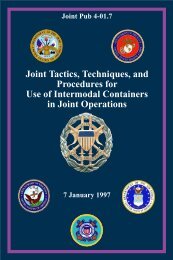
c. The scope of <strong>the</strong> LOTS operation will<br />
depend on geographic, tactical, and time<br />
considerations. A LOTS operation area<br />
(LOA) is <strong>the</strong> geographic area required to<br />
successfully conduct a LOTS operation.<br />
Figure I-1 displays what a typical LOA may<br />
look like.<br />
6. Definition and Scope of<br />
JLOTS Operations<br />
a. JLOTS operations occur when LOTS<br />
elements of <strong>the</strong> Army and Navy conduct<br />
LOTS operations toge<strong>the</strong>r under a JFC.<br />
Traditionally Navy LOTS includes <strong>the</strong> use of<br />
Marine Corps <strong>for</strong>ces. Generally, LOTS<br />
operations will be joint in all but a few<br />
exceptions.<br />
b. The scope of JLOTS operations<br />
extends from acceptance of ships <strong>for</strong> off-load<br />
through <strong>the</strong> arrival of equipment and cargo at<br />
inland staging and marshalling areas.<br />
I-3
Chapter I<br />
I-4<br />
Aviation <strong>Logistics</strong><br />
Support Ship<br />
Maritime Preposition<br />
Ship<br />
Amphibious<br />
Assault Bulk<br />
Water<br />
System<br />
4" Hose<br />
LOTS OPERATION AREA<br />
Roll-On/<br />
Roll-Off<br />
Amphibious<br />
Assault Bulk<br />
Fuel System<br />
6" Hose<br />
Maritime Preposition<br />
Ship<br />
Breakbulk<br />
Maritime Preposition<br />
Ship<br />
Pier Discharge<br />
Hospital<br />
Ship<br />
Auxiliary<br />
Crane Ship<br />
Non-Self-<br />
Sustaining<br />
Containership<br />
Lighter<br />
Aboard Ship<br />
Beach<br />
Landing<br />
Heavy Lift Ship<br />
or Sea Barge<br />
Single Anchor<br />
Leg Mooring<br />
Tanker<br />
Offshore<br />
Petroleum<br />
Discharge<br />
System<br />
Lighters & Elevated Causeway System<br />
Tug<br />
Figure I-1. LOTS Operation Area<br />
Causeway Section, Powered<br />
Causeway Section, Non-Powered<br />
<strong>Joint</strong> Pub 4-01.6
CHAPTER II<br />
ORGANIZATION AND COMMAND<br />
“Organization is <strong>the</strong> vehicle of <strong>for</strong>ce.”<br />
1. <strong>Over</strong>view<br />
This chapter provides a broad overview of<br />
<strong>the</strong> execution of <strong>the</strong> JLOTS operation as<br />
well as <strong>the</strong> C2 of those task organizations<br />
<strong>for</strong>med to per<strong>for</strong>m such operations. A<br />
description and discussion of an amphibious<br />
operation is provided initially to set <strong>the</strong> stage<br />
<strong>for</strong> <strong>the</strong> onset of a JLOTS operation that could<br />
follow. Additionally, this chapter describes<br />
<strong>the</strong> transition that occurs on termination of<br />
an amphibious operation where initial shipto-shore<br />
control is vested with <strong>the</strong> Navy<br />
component and is ultimately passed to Army<br />
<strong>for</strong>ces <strong>for</strong> LOTS operations. Planners should<br />
understand that a JLOTS operation can be<br />
executed without an amphibious operation<br />
preceding it.<br />
2. Command and Organization<br />
Forces assigned to conduct <strong>the</strong> JLOTS<br />
operation are organized by <strong>the</strong> JFC, who<br />
is assigned in accordance with <strong>the</strong> guidance<br />
in <strong>Joint</strong> Pub 0-2, “Unified Action Armed<br />
Forces (UNAAF).” (The term “joint <strong>for</strong>ce”<br />
used in this publication refers to unified<br />
commands, subordinate unified commands,<br />
or JTFs.) The JLOTS <strong>for</strong>ces are normally<br />
organized along functional lines, with<br />
Service elements integrated under <strong>the</strong> tactical<br />
control (TACON) of <strong>the</strong> JLOTS commander.<br />
United States Transportation Command<br />
(USTRANSCOM) <strong>for</strong>ces will normally also<br />
be under <strong>the</strong> TACON of <strong>the</strong> JLOTS<br />
commander. The composition of <strong>the</strong> JLOTS<br />
operational staff should contain appropriate<br />
representation of participating Service<br />
components. Each Service’s senior officer<br />
or noncommissioned officer within <strong>the</strong><br />
MGEN J.F.C. Fuller<br />
The Foundation of <strong>the</strong> Science of War, 1926<br />
JLOTS organization should be af<strong>for</strong>ded<br />
access to <strong>the</strong> JLOTS commander and, via <strong>the</strong><br />
JLOTS commander, to higher Service<br />
component commanders to address Servicerelated<br />
concerns or unique administrative<br />
requirements. In order to effectively conduct<br />
JLOTS operations when called on to do so,<br />
JLOTS training and exercises must be<br />
conducted periodically.<br />
3. Responsibilities of <strong>the</strong><br />
Combatant Commanders<br />
Geographic combatant commanders<br />
have overall responsibility <strong>for</strong> JLOTS<br />
operations in <strong>the</strong>ir area of responsibility<br />
(AOR). The geographic combatant<br />
commander may delegate authority to<br />
subunified commanders or JTF commanders<br />
in <strong>the</strong> conduct of <strong>the</strong>ir assigned missions. To<br />
accomplish this, <strong>the</strong> supported and<br />
supporting combatant commanders should<br />
have <strong>the</strong> following responsibilities.<br />
a. Supported CINC<br />
• Identifies potential requirements <strong>for</strong><br />
JLOTS operations during <strong>the</strong> deliberate<br />
planning process and ensures <strong>for</strong>ce<br />
apportionment.<br />
• Develops JLOTS concept of operations<br />
and initiating directive, if <strong>the</strong> JLOTS<br />
operations is controlled directly by <strong>the</strong><br />
combatant command.<br />
• Exercises combatant command<br />
(command authority) (COCOM) of<br />
assigned <strong>for</strong>ces.<br />
II-1
Chapter II<br />
• Ensures security of JLOTS operations<br />
within <strong>the</strong> AOR.<br />
• Allocates resources.<br />
• Designates <strong>the</strong> component to provide <strong>the</strong><br />
JLOTS commander, if <strong>the</strong> JLOTS<br />
operations is controlled directly by <strong>the</strong><br />
combatant command.<br />
• Per<strong>for</strong>ms intelligence threat assessment<br />
during <strong>the</strong> planning phase and develops<br />
indications and warnings intelligence<br />
during execution of JLOTS operations.<br />
• Provides necessary transportation<br />
intelligence on available means of inland<br />
communication, including roads,<br />
railroads, airfields, inland waterways,<br />
and pipelines.<br />
b. Supporting CINCs<br />
• Provide input to supported CINC<br />
regarding concept of operations.<br />
• Provide <strong>for</strong>ces to <strong>the</strong> supported CINC<br />
as directed.<br />
4. Responsibilities of <strong>the</strong> Service<br />
Component Commanders<br />
Service component commanders<br />
normally support JLOTS operations as<br />
follows.<br />
a. Provide recommendations to <strong>the</strong> JFC on<br />
JLOTS operations.<br />
b. Provide, equip, and train active and<br />
reserve <strong>for</strong>ces to meet required delivery<br />
timelines <strong>for</strong> <strong>the</strong> conduct of JLOTS<br />
operations.<br />
c. Develop implementing plans <strong>for</strong> JLOTS<br />
operational contingencies.<br />
II-2<br />
d. Designate JLOTS commander, as<br />
tasked by <strong>the</strong> JFC.<br />
5. Service Component Mission<br />
Responsibilities<br />
Each component has Service personnel and<br />
equipment necessary <strong>for</strong> <strong>the</strong> conduct of LOTS<br />
operations. During <strong>the</strong> planning <strong>for</strong> and<br />
execution of JLOTS operations, each Service<br />
component will furnish such equipment<br />
and per<strong>for</strong>m those tasks required by <strong>the</strong><br />
CINC’s allocation of resources, as<br />
designated in <strong>the</strong> OPLAN and operation<br />
order (OPORD). In Appendix M, “Unit<br />
Capabilities,” Figure M-16 reflects <strong>the</strong><br />
Service elements required to conduct a<br />
number of logistics tasks.<br />
a. US Army. The primary responsibilities<br />
of <strong>the</strong> US Army in JLOTS operations are<br />
listed in Figure II-1.<br />
b. US Navy. The primary responsibilities<br />
of US Navy <strong>for</strong>ces in LOTS and JLOTS<br />
operations are listed in Figure II-2.<br />
c. US Marine Corps. Marine Corps<br />
<strong>for</strong>ces require JLOTS support <strong>for</strong><br />
sustained logistics buildup ashore. They<br />
possess limited capability to augment JLOTS<br />
operations with shore-based tactical motor<br />
transport, materials handling, bulk liquid,<br />
and C2 assets. The Marine Corps primary<br />
responsibilities identified in Figure II-3 are<br />
valid in supporting JLOTS only until <strong>the</strong><br />
Marine air-ground task <strong>for</strong>ce (MAGTF)<br />
commander requires combat service support<br />
element units <strong>for</strong> follow-on Marine Corps<br />
missions.<br />
d. US Coast Guard. The Coast Guard<br />
is organized, trained, and equipped to<br />
provide port safety and security functions<br />
to <strong>the</strong> port area in a LOTS or JLOTS<br />
environment. General functions concerning<br />
<strong>Joint</strong> Pub 4-01.6
Organization and Command<br />
US ARMY PRIMARY RESPONSIBILITIES<br />
Provide <strong>for</strong>ces <strong>for</strong> and conduct JLOTS operations<br />
Provide lighterage, o<strong>the</strong>r discharge equipment, and trained operators<br />
<strong>for</strong> use in JLOTS operations and provide <strong>the</strong> common-Service assets<br />
required to supplement amphibious operations, as available<br />
Provide transport to remove and distribute cargo moving from LOTS<br />
and/or JLOTS sites to inland staging areas to include airfields or<br />
helicopter pick-up zones<br />
In accordance with joint <strong>for</strong>ce commander directives, provide general<br />
water support purification operations, diving support, and assistance<br />
in deployment of barge-to-shore pipeline to <strong>the</strong> shoreside high<br />
watermark where <strong>the</strong> pipeline connects with <strong>the</strong> potable water<br />
storage and distribution system of <strong>the</strong> land <strong>for</strong>ces<br />
Select, in conjunction with <strong>the</strong> Navy component commander, JLOTS<br />
landing sites<br />
Prepare unimproved beach surfaces and backwater surfaces to<br />
enhance trafficability of materiel and equipment to major rail and road<br />
networks<br />
Prepare marshalling areas <strong>for</strong> <strong>the</strong> storage of containers, breakbulk<br />
cargo, and rolling stock<br />
Emplace inland petroleum distribution systems to support bulk fuel<br />
discharge operations inland from <strong>the</strong> shore side high water mark<br />
Provide communications between <strong>the</strong> offshore petroleum discharge<br />
system tanker and <strong>the</strong> shore<br />
Establish cargo discharge facilities -- such as floating causeway piers<br />
-- in support of dry cargo discharge<br />
Figure II-1. US Army Primary Responsibilities<br />
harbor and port security are covered in Naval<br />
Warfare Publication (NWP) 3-10, “Naval<br />
Coastal Warfare.” If requested, <strong>the</strong> Coast<br />
Guard may provide as a unit or as individual<br />
components port security units, port safety<br />
and/or security boarding teams, and high<br />
endurance cutters or patrol boats. The teams<br />
that make up <strong>the</strong> details, depending on<br />
specialty, will assist <strong>the</strong> JLOTS commander<br />
by providing elements trained in port security<br />
and port safety to help ensure <strong>the</strong> security of<br />
vessels, port facilities, and cargo as well as<br />
<strong>the</strong> safety of cargo operations during outload<br />
and off-load operations. Coast Guard <strong>for</strong>ces<br />
II-3
Chapter II<br />
II-4<br />
US NAVY PRIMARY RESPONSIBILITIES<br />
Provide, as required by <strong>the</strong> joint <strong>for</strong>ce commander,<br />
appropriate naval <strong>for</strong>ces and equipment<br />
Exercise command of Navy ships and boats to ensure safe<br />
and proper operation and to take action against <strong>the</strong> enemy, if<br />
necessary<br />
Exercise a minimum of tactical control over <strong>the</strong> disposition<br />
and operation of o<strong>the</strong>r participating ships as necessary to<br />
protect <strong>the</strong>m<br />
Provide <strong>for</strong> offshore petroleum discharge to <strong>the</strong> shoreside<br />
high water mark<br />
Provide lighterage, o<strong>the</strong>r discharge equipment, and trained<br />
operators <strong>for</strong> use in JLOTS operations and common-Service<br />
assets as required<br />
Provide potable water as directed by <strong>the</strong> joint <strong>for</strong>ce<br />
commander<br />
Select, in conjunction with a land commander, <strong>the</strong> LOTS<br />
operation area and LOTS landing sites<br />
Erect cargo discharge facilities, such as <strong>the</strong> elevated<br />
causeway system, in support of dry cargo discharge<br />
operations<br />
Conduct beach party operations, including control and<br />
salvage of lighterage and control of <strong>the</strong> beach transit of<br />
disembarked vehicles and cargo<br />
Provide mobile inshore undersea warfare units <strong>for</strong> seaward<br />
surveillance in support of JLOTS security<br />
Construct expeditionary facilities to support beach operations<br />
and enhance throughput, provide camp support, and security<br />
Figure II-2. US Navy Primary Responsibilities<br />
<strong>Joint</strong> Pub 4-01.6
US MARINE CORPS PRIMARY<br />
RESPONSIBILITIES<br />
are committed to CINC support missions<br />
through <strong>the</strong> 1995 Secretary of Department<br />
of Transportation and Secretary of Defense<br />
memorandum of agreement (MOA). Coast<br />
Guard LOTS and JLOTS support assets<br />
should be included in a CINC’s deliberate<br />
planning process. JLOTS is considered an<br />
extension of <strong>the</strong> traditional deployed port<br />
operations, security and defense mission.<br />
This mission includes protecting shipping<br />
and harbor security from waterborne threats.<br />
JLOTS is an expeditionary port in<br />
comparison to normal Coast Guard<br />
operations. Coast Guard elements will<br />
require space <strong>for</strong> refueling of patrol craft and<br />
billeting space, if not deployed ashore, and<br />
normal logistic support. Coast Guard <strong>for</strong>ces<br />
work in conjunction with mobile inshore<br />
undersea warfare (MIUW) units to provide<br />
surveillance and interdiction in <strong>the</strong> seaward<br />
operational area in accordance with naval<br />
Organization and Command<br />
Provide <strong>the</strong> materials handling and motor transport<br />
personnel and equipment to receive and transport cargo<br />
moving from <strong>the</strong> beach support area<br />
Provide potable water and its storage facilities<br />
Prepare unimproved beach surfaces and backwater surface<br />
to enhance movement of materials and equipment to<br />
marshalling areas<br />
Prepare marshalling areas <strong>for</strong> containerized and breakbulk<br />
cargo and rolling stock<br />
Emplace tactical fuel storage and distribution systems to<br />
support bulk fuel operations within <strong>the</strong> amphibious objective<br />
area<br />
Figure II-3. US Marine Corps Primary Responsibilities<br />
coastal warfare doctrine contained in NWP<br />
3-10, “Naval Coastal Warfare,” and NWP<br />
3-10.3, “Inshore Undersea Warfare.” It<br />
should be noted that Coast Guard units and<br />
details are not self-sufficient and must be<br />
supported by <strong>the</strong> receiving commander,<br />
particularly when deployed outside <strong>the</strong><br />
continental United States.<br />
6. Responsibilities of <strong>the</strong> JLOTS<br />
Commander<br />
The JLOTS commander is responsible<br />
<strong>for</strong> detailed planning and execution of<br />
JLOTS operations. This will be<br />
accomplished through a central planning<br />
team composed of representatives from<br />
participating Service and USTRANSCOM<br />
components. Regardless of <strong>the</strong> Service<br />
providing <strong>the</strong> JLOTS commander,<br />
responsibilities and procedures <strong>for</strong> <strong>the</strong><br />
II-5
Chapter II<br />
conduct of JLOTS operations remain <strong>the</strong><br />
same. Principal responsibilities of <strong>the</strong><br />
JLOTS commander are as follows.<br />
a. Publish an OPORD or directive that<br />
states responsibilities of all <strong>for</strong>ces under<br />
TACON and describes procedures <strong>for</strong> <strong>the</strong><br />
conduct of <strong>the</strong> JLOTS operation.<br />
b. Handle JLOTS execution, beginning<br />
with acceptance of ships <strong>for</strong> off-load, through<br />
<strong>the</strong> arrival of equipment and cargo at inland<br />
staging and marshalling areas.<br />
c. Coordinate over-<strong>the</strong>-shore liquid<br />
cargo operations. For OPDS, responsibility<br />
includes acceptance of OPDS vessels and <strong>the</strong><br />
installation and operation of OPDS to its<br />
termination point on <strong>the</strong> beach, where it<br />
interfaces with <strong>the</strong> inland petroleum<br />
distribution systems (IPDSs) and <strong>the</strong><br />
amphibious assault bulk fuel system (AABFS).<br />
7. Common-User Sealift<br />
The COCOM of common-user sealift in<br />
support of a JLOTS operation remains with<br />
USCINCTRANS unless transferred to <strong>the</strong><br />
commander of ano<strong>the</strong>r unified command as<br />
directed by <strong>the</strong> Secretary of Defense.<br />
Operational control (OPCON) is usually<br />
delegated to <strong>the</strong> Commander, Military Sealift<br />
Command (COMSC) or <strong>the</strong> designated<br />
subordinate. TACON is usually assigned to<br />
<strong>the</strong> supported CINC and delegated to <strong>the</strong> onscene<br />
naval officer in tactical command<br />
(OTC).<br />
a. The OTC will act as <strong>the</strong> sole contact<br />
with strategic sealift shipping at <strong>the</strong><br />
JLOTS site <strong>for</strong> tactical matters and will issue<br />
sailing orders to ships in coordination with<br />
<strong>the</strong> JLOTS commander and <strong>the</strong> MSC area<br />
commander’s representative. The JLOTS<br />
commander is subordinate and responds to<br />
<strong>the</strong> OTC in tactical matters affecting strategic<br />
shipping involved in <strong>the</strong> JLOTS operation.<br />
In addition to <strong>the</strong> normal duties, <strong>the</strong> MSC<br />
II-6<br />
area representative serves as a special staff<br />
adviser to <strong>the</strong> JLOTS commander and is <strong>the</strong><br />
JLOTS commander’s point of contact <strong>for</strong><br />
operational matters dealing with strategic<br />
shipping in <strong>the</strong> JLOTS operational area. The<br />
MSC representative is normally located<br />
aboard ship. If <strong>the</strong> MSC representative has<br />
<strong>the</strong> personnel available, one of <strong>the</strong> MSC<br />
representatives should be located with <strong>the</strong><br />
JLOTS commander. Rapid communication<br />
and coordination between <strong>the</strong> JLOTS<br />
commander and MSC representative are<br />
essential <strong>for</strong> efficient operations.<br />
b. Specific discussion relative to authority<br />
and responsibilities of <strong>the</strong> ship master and<br />
coordination with embarked military units<br />
is detailed in Appendix K, “Command,<br />
Organization, and Working Relationships<br />
with Civilian Merchant Mariners.”<br />
8. C2 Relationships<br />
C2 relationships are as prescribed by <strong>Joint</strong><br />
Pub 0-2, “Unified Action Armed Forces<br />
(UNAAF).” The following conditions<br />
apply.<br />
a. In an amphibious operation, command<br />
and inter-Service relationships will be<br />
guided by <strong>Joint</strong> Pub 3-02, “<strong>Joint</strong> Doctrine <strong>for</strong><br />
Amphibious Operations.”<br />
b. In JLOTS operations, Service elements<br />
must be integrated under one JLOTS<br />
commander who normally has TACON<br />
authority to task-organize elements as<br />
necessary. Service elements should be<br />
employed in a manner consistent with <strong>the</strong>ir<br />
training, unit, and job description. They<br />
should be af<strong>for</strong>ded access to <strong>the</strong> JLOTS<br />
commander and, via <strong>the</strong> JLOTS commander,<br />
to higher Service component commanders <strong>for</strong><br />
Service-related issues. Responsibilities and<br />
details <strong>for</strong> all aspects of <strong>the</strong> JLOTS operation<br />
are provided in an OPORD or o<strong>the</strong>r<br />
appropriate document prepared by <strong>the</strong> JLOTS<br />
commander.<br />
<strong>Joint</strong> Pub 4-01.6
c. Specific JLOTS operations will be<br />
identified by <strong>the</strong> JFC during concept<br />
development. At that time, tentative JLOTS<br />
sites will be selected and <strong>for</strong>ce requirements<br />
identified. Landing sites will be selected by<br />
agreement between <strong>the</strong> supporting Navy<br />
component commander and <strong>the</strong> JLOTS<br />
commander and will be approved by <strong>the</strong> JFC.<br />
The JLOTS commander is responsible <strong>for</strong><br />
consideration of <strong>the</strong> inland access<br />
requirements.<br />
d. The JLOTS commander will<br />
coordinate <strong>the</strong> positioning of ships <strong>for</strong><br />
JLOTS operations at <strong>the</strong> selected landing<br />
sites with <strong>the</strong> supporting Navy component<br />
commander, in accordance with priorities<br />
established by <strong>the</strong> JFC.<br />
e. JLOTS operations may follow<br />
amphibious operations that are routinely <strong>the</strong><br />
responsibility of <strong>the</strong> Navy. The transition<br />
from amphibious to JLOTS operations will<br />
entail passing TACON of <strong>the</strong> off-load site(s)<br />
and logistics landing <strong>for</strong>ce from <strong>the</strong><br />
commander, amphibious task <strong>for</strong>ce (CATF)<br />
to <strong>the</strong> JLOTS commander once <strong>the</strong><br />
amphibious operation is terminated. This<br />
transition will be accomplished as directed<br />
by <strong>the</strong> JFC or in accordance with <strong>the</strong> JFC’s<br />
initiating directive or OPORD. Off-load<br />
assets that are at <strong>the</strong> site of an amphibious<br />
operation would normally be retained by <strong>the</strong><br />
on-scene maritime <strong>for</strong>ce commander at <strong>the</strong><br />
termination of <strong>the</strong> amphibious operations.<br />
Any exception to this procedure must be<br />
approved by <strong>the</strong> JFC. If <strong>the</strong> OPORD or JFC<br />
directs that amphibious task <strong>for</strong>ce (ATF) offload<br />
assets be diverted to subsequent LOTS<br />
and JLOTS operations as <strong>the</strong> off-load<br />
transitions to Army LOTS, those assets<br />
should be recovered at <strong>the</strong> earliest practical<br />
moment <strong>for</strong> fur<strong>the</strong>r employment in <strong>the</strong>ir<br />
primary amphibious function.<br />
f. During ship-to-shore operations,<br />
command relationships are as follows.<br />
Organization and Command<br />
• During an amphibious operation, <strong>the</strong><br />
CATF is responsible <strong>for</strong> <strong>the</strong> ship-to-shore<br />
movement. The CATF exercises this<br />
control through a Navy control group<br />
(See Figure II-4).<br />
• With <strong>the</strong> termination of <strong>the</strong><br />
amphibious operation, <strong>the</strong> ATF is<br />
disestablished and a transition is made<br />
from amphibious operation to LOTS or<br />
JLOTS. Normally, this transition<br />
involves a period in which <strong>the</strong> Navy and<br />
supported Marine Corps or Army <strong>for</strong>ces<br />
continue to conduct ship-to-shore<br />
movement using <strong>the</strong> basic control<br />
organization and procedures used <strong>for</strong> <strong>the</strong><br />
amphibious operation. As Army<br />
transportation units arrive in <strong>the</strong> area,<br />
<strong>the</strong>y report to <strong>the</strong>ir Service component<br />
but functionally integrate into <strong>the</strong><br />
existing Navy and Marine Corps or<br />
Army cargo discharge organization. The<br />
JLOTS ship-to-shore C2 organization,<br />
when operationally ready and directed<br />
by <strong>the</strong> JFC, will assume TACON of <strong>the</strong><br />
JLOTS operation. Control of all shipto-shore<br />
assets is transferred from <strong>the</strong><br />
Navy component commander to <strong>the</strong><br />
JLOTS organization. Navy ship-toshore<br />
assets not already withdrawn will<br />
remain under <strong>the</strong> TACON of <strong>the</strong> JLOTS<br />
commander but will be phased out as<br />
directed in <strong>the</strong> OPORD. Ship-to-shore<br />
JLOTS command relationships are<br />
shown in Figure II-5.<br />
9. Amphibious Operations<br />
a. Background. An amphibious<br />
operation is an attack launched from <strong>the</strong><br />
sea by naval and landing <strong>for</strong>ces embarked<br />
in ships or craft involving a landing on a<br />
hostile or potentially hostile shore. Forces<br />
assigned to conduct an amphibious operation<br />
are organized as an ATF or, when <strong>the</strong> criteria<br />
<strong>for</strong> a JTF are met, a joint amphibious task<br />
<strong>for</strong>ce. <strong>Joint</strong> Pub 3-02, “<strong>Joint</strong> Doctrine <strong>for</strong><br />
II-7
Chapter II<br />
II-8<br />
COMMAND RELATIONSHIP DURING<br />
AMPHIBIOUS OPERATION<br />
SHIP-TO-SHORE MOVEMENTS<br />
O<strong>the</strong>r<br />
Component<br />
Commanders<br />
Commanders<br />
of Subordinate<br />
Service Forces<br />
Surface Control<br />
Group<br />
Commander<br />
Tactical Air/Helo<br />
Control Group<br />
Commander<br />
Transportation<br />
Group<br />
Commanders<br />
O<strong>the</strong>r Task Group<br />
Commanders<br />
<strong>Joint</strong> Force<br />
Commander<br />
Navy<br />
Component<br />
Commander<br />
Commander,<br />
Amphibious<br />
Task Force<br />
LEGEND<br />
O<strong>the</strong>r <strong>Joint</strong><br />
Task Force<br />
Commanders<br />
Commander,<br />
Landing Force<br />
Commander,<br />
Landing Force<br />
Support Party<br />
Operational Control<br />
Coordination<br />
Administrative<br />
Control<br />
Figure II-4. Command Relationship During Amphibious Operation<br />
Ship-to-<strong>Shore</strong> Movements<br />
<strong>Joint</strong> Pub 4-01.6
Organization and Command<br />
COMMAND RELATIONSHIP DURING JLOTS<br />
SHIP-TO-SHORE MOVEMENTS<br />
O<strong>the</strong>r<br />
Component<br />
Commanders<br />
Service Element<br />
Commanders<br />
LEGEND<br />
Operational Control<br />
Tactical Control<br />
Coordination<br />
Administrative<br />
Control<br />
<strong>Joint</strong> Force<br />
Commander<br />
Component<br />
Commander<br />
Commander,<br />
<strong>Joint</strong> <strong>Logistics</strong><br />
<strong>Over</strong>-<strong>the</strong>-<br />
<strong>Shore</strong><br />
O<strong>the</strong>r <strong>Joint</strong><br />
Task Force<br />
Commanders<br />
Military Sealift<br />
Command Area<br />
Commander<br />
Task Organized Unit<br />
Commander(s)<br />
Lighterage Units<br />
<strong>Shore</strong> Beach Units<br />
Ship Cargo<br />
Handling Units<br />
Terminal Service Units<br />
<strong>Joint</strong> <strong>Logistics</strong> <strong>Over</strong><strong>the</strong>-<strong>Shore</strong><br />
Security<br />
Units<br />
Figure II-5. Command Relationship During JLOTS Ship-to-<strong>Shore</strong> Movements<br />
II-9
Chapter II<br />
Amphibious Operations,” contains detailed<br />
doctrine <strong>for</strong> amphibious operations. A<br />
condensed discussion is presented here to set<br />
<strong>the</strong> stage of transition into JLOTS. Items<br />
pertaining to <strong>the</strong>se operations are as<br />
follows.<br />
• Amphibious operations may be<br />
conducted <strong>for</strong> <strong>the</strong> purposes listed in<br />
Figure II-6.<br />
• The amphibious operation is separate<br />
and distinct, but is also usually part of<br />
a campaign or operation of greater<br />
magnitude. As an entity, <strong>the</strong> typical<br />
amphibious operation includes planning<br />
and embarkation of landing <strong>for</strong>ces and<br />
equipment, rehearsal, movement to <strong>the</strong><br />
amphibious objective area (AOA),<br />
landing of <strong>for</strong>ces with accompanying<br />
supplies and equipment, and support of<br />
<strong>the</strong> landing <strong>for</strong>ce until termination of <strong>the</strong><br />
amphibious operation. Movement of<br />
<strong>the</strong> landing <strong>for</strong>ce to or from <strong>the</strong><br />
objective area is made predominantly<br />
by Navy surface ships but also includes<br />
movement by self-deployed aircraft, Air<br />
Mobility Command (AMC) airlift, MSC<br />
sealift, or commercial ships. All ships<br />
assigned to <strong>the</strong> ATF are called assault<br />
II-10<br />
Prosecute fur<strong>the</strong>r combat operations<br />
shipping. Movement between assault<br />
shipping (including both Navy and<br />
commercial ships assigned to <strong>the</strong> ATF)<br />
and <strong>the</strong> hostile shore is made by landing<br />
craft, amphibious vehicles, and<br />
helicopters. The operation focuses on<br />
ship-to-shore movement of <strong>the</strong> landing<br />
<strong>for</strong>ce from <strong>the</strong> assault shipping to<br />
designated landing areas in accordance<br />
with <strong>the</strong> tactical requirements of <strong>the</strong><br />
commander, landing <strong>for</strong>ce (CLF).<br />
Administrative unloading of personnel<br />
and materiel from ships may be<br />
conducted after security has been assured<br />
through seizure and control of adequate<br />
land areas and adjacent sea areas to<br />
ensure unimpeded discharge of<br />
personnel and cargo.<br />
• The ATF is a task organization <strong>for</strong>med<br />
<strong>for</strong> <strong>the</strong> purpose of conducting <strong>the</strong><br />
specific amphibious operation. The<br />
ATF always includes Navy <strong>for</strong>ces and a<br />
landing <strong>for</strong>ce with <strong>the</strong>ir organic aviation,<br />
and may include MSC-provided ships<br />
and Air Force <strong>for</strong>ces when appropriate.<br />
The CATF is designated by higher<br />
authority based on <strong>the</strong> mission and<br />
composition of <strong>the</strong> ATF. The CATF<br />
plans and executes <strong>the</strong> deployment of<br />
PURPOSES OF AMPHIBIOUS OPERATIONS<br />
Obtain a site <strong>for</strong> an advanced naval, land, or air base<br />
Deny use of an area or facilities to <strong>the</strong> enemy<br />
Fix enemy <strong>for</strong>ces and attention, providing opportunities <strong>for</strong><br />
o<strong>the</strong>r combat operations<br />
Figure II-6. Purposes of Amphibious Operations<br />
<strong>Joint</strong> Pub 4-01.6
<strong>for</strong>ces by all transportation modes and<br />
<strong>the</strong> landing of all <strong>for</strong>ces and supplies in<br />
accordance with <strong>the</strong> requirements of <strong>the</strong><br />
CLF. For movement, <strong>the</strong> ATF may be<br />
organized into an advance <strong>for</strong>ce (pre-Dday)<br />
and a main body (D-day and post-<br />
D-day). The landing <strong>for</strong>ce is divided<br />
into two echelons — <strong>the</strong> assault echelon<br />
(AE) and <strong>the</strong> AFOE.<br />
b. Assault Echelon. The AE consists of<br />
<strong>the</strong> assault troops, vehicles, aircraft,<br />
equipment, and supplies required to initiate<br />
<strong>the</strong> assault landing. Also, it may include<br />
landing <strong>for</strong>ces staged by any mode to advance<br />
support bases near <strong>the</strong> objective area be<strong>for</strong>e<br />
<strong>the</strong> assault. Pre-staged <strong>for</strong>ces at advanced<br />
support bases provide initial combat<br />
capability in addition to those <strong>for</strong>ces<br />
embarked in Navy amphibious ships.<br />
c. Assault Follow-on Echelon. The<br />
AFOE consists of <strong>the</strong> assault troops, vehicles,<br />
aircraft, equipment, and supplies that, though<br />
not needed to initiate <strong>the</strong> assault, are required<br />
to support and sustain <strong>the</strong> assault. To<br />
accomplish its purpose, <strong>the</strong> AFOE is<br />
normally required in <strong>the</strong> objective area no<br />
later than 5 days after commencement of<br />
<strong>the</strong> assault landing.<br />
d. AE and AFOE Considerations.<br />
Considerations pertaining to <strong>the</strong> AE and<br />
AFOE include <strong>the</strong> following.<br />
• Loading and unloading of <strong>the</strong> AE and<br />
AFOE are <strong>the</strong> responsibility of <strong>the</strong><br />
CATF. Units and unit equipment are<br />
marshalled at <strong>the</strong>ir home stations and<br />
staged at ports of embarkation in<br />
accordance with <strong>the</strong>ir time-phased<br />
deployment schedules. Ships are<br />
combat-loaded to facilitate expected<br />
requirements of <strong>the</strong> concept of operations<br />
ashore and <strong>the</strong> supporting landing plan.<br />
Ship unloading is accomplished by <strong>the</strong><br />
normal Navy ship-to-shore control and<br />
support agencies’ central control officer,<br />
Organization and Command<br />
Helicopter Direction Center, tactical<br />
logistic group, and <strong>the</strong> landing <strong>for</strong>ce<br />
support party (LFSP). The CATF<br />
exercises overall control of <strong>the</strong> shipto-shore<br />
movement. The CATF is<br />
responsible <strong>for</strong> debarkation and off-load<br />
until termination of <strong>the</strong> amphibious<br />
operation, when <strong>the</strong> responsibilities <strong>for</strong><br />
debarkation or off-load are passed to<br />
ano<strong>the</strong>r off-load organization designated<br />
by higher authority. (The amphibious<br />
operation would not normally be<br />
terminated until <strong>the</strong> AFOE is ashore.)<br />
The CLF in<strong>for</strong>ms <strong>the</strong> CATF of <strong>the</strong><br />
requirements <strong>for</strong> units, materiel, and<br />
supplies, and specifies <strong>the</strong> time at which<br />
<strong>the</strong>y will be required. The CLF is<br />
responsible <strong>for</strong> <strong>the</strong> movement of cargo<br />
within <strong>the</strong> beach support area and into<br />
inland combat service support (CSS)<br />
areas. Since most MSC-provided ships<br />
have nei<strong>the</strong>r <strong>the</strong> organic off-load<br />
capabilities nor <strong>the</strong> organic ability to<br />
control debarkation of embarked troops<br />
or cargo, <strong>the</strong>ir off-load is conducted by<br />
<strong>the</strong> ATF with naval or landing <strong>for</strong>ce<br />
personnel and equipment.<br />
• Shipping used to resupply <strong>the</strong> ATF or to<br />
transport additional units, supplies, and<br />
equipment required <strong>for</strong> <strong>the</strong> buildup of<br />
<strong>the</strong> beachhead is called follow-on<br />
shipping. Essentially, follow-on<br />
shipping delivers rein<strong>for</strong>cements and<br />
stores after <strong>the</strong> AE and AFOE have<br />
been landed. This shipping is provided<br />
by <strong>the</strong> commander of a unified command<br />
and is echeloned into <strong>the</strong> AOA as<br />
required by <strong>the</strong> CATF. The CATF<br />
provides protection <strong>for</strong> and controls both<br />
assault and follow-on shipping within<br />
<strong>the</strong> AOA. The CATF orders shipping<br />
<strong>for</strong>ward, as necessary, to fulfill <strong>the</strong> needs<br />
of <strong>the</strong> landing <strong>for</strong>ce <strong>for</strong> units, materiel,<br />
and supplies. Upon unloading, empty<br />
follow-on shipping assets are returned<br />
to a location where USTRANSCOM,<br />
through MSC, assumes employment<br />
II-11
Chapter II<br />
II-12<br />
responsibility <strong>for</strong> <strong>the</strong>m. Additionally, <strong>the</strong><br />
MSC commander, under <strong>the</strong> numbered<br />
fleet commander, assumes responsibility<br />
<strong>for</strong> coordinating protection of shipping.<br />
Upon disestablishment of <strong>the</strong> AOA,<br />
control of follow-on shipping passes<br />
from <strong>the</strong> CATF to <strong>the</strong> Navy OTC or<br />
JLOTS commander, as appropriate.<br />
10. Transition to JLOTS<br />
Operations<br />
As a function of <strong>the</strong> on-scene Service<br />
component <strong>for</strong>ce capabilities, several<br />
possible transitions may occur in assuming<br />
control of <strong>the</strong> off-load.<br />
a. Be<strong>for</strong>e termination of <strong>the</strong> amphibious<br />
operation, some Army off-load elements<br />
may have arrived or be arriving in <strong>the</strong><br />
landing area. Control of those Army units<br />
that are normally associated with <strong>the</strong> shipto-shore<br />
movement is passed to <strong>the</strong> CATF.<br />
Likewise, control of any shore-based Army<br />
units will be vested with <strong>the</strong> CLF. Army<br />
elements will be incorporated into <strong>the</strong><br />
existing ship-to-shore organization described<br />
in Figure II-7.<br />
b. Upon termination of an amphibious<br />
operation, as directed by a JFC, a<br />
transition to LOTS or JLOTS operations<br />
is conducted. If all discharge <strong>for</strong>ces in an<br />
operation remain Navy and Marine Corps, it<br />
is considered a Navy LOTS operation, which<br />
normally continues under <strong>the</strong> control of <strong>the</strong><br />
Navy component commander. The same<br />
basic control organization exists as during<br />
<strong>the</strong> amphibious operation (See Figure II-8).<br />
As Army discharge <strong>for</strong>ces arrive and are<br />
incorporated with <strong>the</strong> Navy and/or Marine<br />
Corps personnel, <strong>the</strong> discharge becomes a<br />
JLOTS.<br />
c. Upon mutual agreement between <strong>the</strong><br />
Navy OTC and <strong>the</strong> designated JLOTS<br />
commander, or when directed by <strong>the</strong> JFC,<br />
<strong>the</strong> JLOTS commander assumes <strong>the</strong><br />
responsibility <strong>for</strong> JLOTS through <strong>the</strong><br />
organizations depicted in Figure II-8.<br />
Whe<strong>the</strong>r <strong>the</strong> JLOTS commander is from <strong>the</strong><br />
Navy or Army component, normally <strong>the</strong> Navy<br />
off-load support personnel and applicable<br />
Marine Corps LFSP personnel and<br />
equipment will be transferred to <strong>the</strong> TACON<br />
of <strong>the</strong> JLOTS commander and be assimilated<br />
into appropriate task organizations until <strong>the</strong><br />
JFC releases Navy and Marine Corps <strong>for</strong>ces<br />
to reembark aboard amphibious shipping to<br />
prepare <strong>for</strong> a future potential amphibious<br />
operation. Army off-load elements associated<br />
with <strong>the</strong> ship-to-shore movement need to be<br />
integrated into <strong>the</strong> JLOTS organization by<br />
being transferred to <strong>the</strong> JLOTS commander.<br />
The JLOTS commander’s responsibility <strong>for</strong><br />
cargo and/or equipment delivery extends<br />
from ship acceptance <strong>for</strong> off-loading through<br />
arrival of cargo and/or equipment at inland<br />
staging and marshalling areas.<br />
d. As required in <strong>the</strong> CINC’s and/or<br />
subordinate JFC’s OPORD, <strong>the</strong> naval offload<br />
personnel and equipment may phase<br />
out of <strong>the</strong> specific operation being<br />
supported by <strong>the</strong> JLOTS commander to<br />
be available <strong>for</strong> support of o<strong>the</strong>r operations.<br />
Naval elements will be transferred from <strong>the</strong><br />
JLOTS commander to <strong>the</strong> Navy component<br />
commander. Ultimately, <strong>the</strong> JLOTS<br />
operations may transition to Army LOTS.<br />
<strong>Joint</strong> Pub 4-01.6
Primary Control<br />
Officer 1/<br />
Helo Direction<br />
Center 2/<br />
Transport<br />
Groups<br />
LEGEND<br />
TACLOG<br />
1/<br />
2/<br />
3/<br />
Operational Control<br />
Coordination<br />
Tactical-Logistical<br />
Group<br />
Per colored<br />
numbered beach or<br />
helicopter landing<br />
zone<br />
Used in helo ship-toshore<br />
Landing <strong>for</strong>ce units<br />
operational control<br />
primary control<br />
officer/helicopter<br />
direction center <strong>for</strong><br />
ship-to-shore<br />
movement<br />
Organization and Command<br />
ORGANIZATION FOR AMPHIBIOUS<br />
SHIP-TO-SHORE OPERATIONS<br />
Central Control<br />
Officer Tactical<br />
Control Center 2/<br />
Lighterage<br />
Groups<br />
Amphibious Task Force<br />
Landing<br />
Force<br />
TACLOG<br />
TACLOG<br />
Group<br />
Cargo<br />
Handling<br />
Detachment<br />
Landing<br />
Force<br />
Elements<br />
HELO/<br />
Assault<br />
Amphibian<br />
Vehicle<br />
Units 3/<br />
Landing Force<br />
<strong>Shore</strong> Party<br />
Group 1/ Helo<br />
Support Team<br />
2/<br />
Headquarters<br />
Beach<br />
Party<br />
Group<br />
<strong>Shore</strong> Party / Landing<br />
Zone Platoon<br />
Motor Transport /<br />
Heavy Equipment Platoon<br />
Service Platoon<br />
HELO Control Platoon 2/<br />
Force Security<br />
Organization<br />
Landing<br />
Force<br />
Support<br />
Party<br />
Figure II-7. Organization <strong>for</strong> Amphibious Ship-to-<strong>Shore</strong> Operations<br />
II-13
Chapter II<br />
II-14<br />
ORGANIZATION FOR NAVY LOTS SUBSEQUENT<br />
TO AMPHIBIOUS OPERATIONS<br />
Officer in Tactical<br />
Command, Naval Task<br />
Force<br />
Beach<br />
Support<br />
Group<br />
LEGEND<br />
1 /<br />
2 /<br />
Off-load<br />
Coordinator 1/<br />
(Formerly Central Control<br />
Officer/Primary Control<br />
Officer Amphibious<br />
Operations)<br />
Lighterage<br />
Groups<br />
2/<br />
Operational Control<br />
Coordination<br />
Support<br />
Controls surface movement only;<br />
helicopter movement addressed<br />
on a case-by-case basis<br />
Per colored beach<br />
Cargo<br />
Handling<br />
Detachments<br />
2/<br />
Commander<br />
Supported<br />
USMC/USA Force<br />
Ashore<br />
Combat Service<br />
Support Element<br />
Commander<br />
Beach<br />
Party<br />
Group<br />
2/<br />
Combat<br />
Service<br />
Support<br />
Detachment<br />
Commanders<br />
Fuels Element<br />
Elevated Causeway<br />
System Element<br />
Pier Element<br />
Security Elements<br />
Roll-on/Roll-off<br />
Discharge Facility<br />
Element<br />
Figure II-8. Organization <strong>for</strong> Navy <strong>Logistics</strong> <strong>Over</strong>-<strong>the</strong>-<strong>Shore</strong><br />
Subsequent to Amphibious Operations<br />
<strong>Joint</strong> Pub 4-01.6
CHAPTER III<br />
PLANNING JLOTS OPERATIONS<br />
“In war nothing is achieved except by calculation. Everything that is not<br />
soundly planned in its details yields no result.”<br />
1. <strong>Over</strong>view<br />
Planning <strong>for</strong> JLOTS operations is<br />
complicated by <strong>the</strong> need <strong>for</strong> detailed<br />
coordination between <strong>the</strong> various Service<br />
<strong>for</strong>ces involved, <strong>the</strong> complex logistic<br />
activities, joint command relationships,<br />
geographic distance between ships and<br />
marshalling yards, and o<strong>the</strong>r peculiar<br />
operational factors. JLOTS tests reveal <strong>the</strong><br />
need <strong>for</strong> complete and detailed planning. This<br />
chapter discusses operation planning<br />
procedures and considerations valid in both<br />
deliberate and crisis action planning.<br />
2. Responsibilities<br />
Planning responsibilities are outlined in<br />
Chapter II, “Organization and Command.”<br />
3. Operation Planning<br />
a. Planning Procedures. Planning<br />
procedures used by <strong>the</strong> JLOTS commanders<br />
should basically follow those shown below.<br />
• Receive and analyze <strong>the</strong> mission to be<br />
accomplished.<br />
• Conduct terrain analysis, review <strong>the</strong><br />
enemy situation, and begin collecting<br />
necessary intelligence <strong>for</strong> <strong>the</strong> JLOTS site<br />
location.<br />
• Develop and compare alternative courses<br />
of action as <strong>the</strong>y apply to JLOTS<br />
operations.<br />
• Select <strong>the</strong> best alternative.<br />
Napoleon<br />
• Develop and obtain approval <strong>for</strong> its<br />
concept.<br />
• Prepare a plan.<br />
• Publish <strong>the</strong> plan.<br />
As <strong>the</strong> above procedures are executed, <strong>the</strong><br />
JLOTS commander must provide early<br />
and continuous dissemination of planning<br />
data to senior, subordinate, supporting, and<br />
supported commanders. Additionally, staff<br />
officers and/or staff noncommissioned officers<br />
and liaison officers that are to be assigned to<br />
<strong>the</strong> JLOTS staff should be assigned as early<br />
as possible in <strong>the</strong> planning phase.<br />
b. Concurrent Planning. Because many<br />
of <strong>the</strong> planning problems are of mutual<br />
concern to all participants, concurrent<br />
planning is necessary. The allocation of<br />
resources, such as available shipping,<br />
lighterage, ship-to-shore transfer systems, and<br />
LOTS equipment, will be based on <strong>the</strong> amount<br />
of equipment, dry cargo, bulk fuel, and water<br />
that must be discharged to meet <strong>the</strong> needs of<br />
supported <strong>for</strong>ces. The plans of supported<br />
<strong>for</strong>ces must be sufficiently advanced to<br />
provide a basis <strong>for</strong> determining requirements<br />
and <strong>for</strong> setting discharge priorities.<br />
c. Throughput Planning. Throughput<br />
is <strong>the</strong> average movement of containers,<br />
wheeled vehicles, tracked vehicles, breakbulk<br />
cargo, and bulk liquid cargo that can pass<br />
through a port or beach daily. It covers<br />
movement from arrival at <strong>the</strong> port or instream,<br />
to off-loading cargo onto lighters or<br />
piers, to <strong>the</strong> exit or clearance from bare beach<br />
III-1
Chapter III<br />
or port complex. Throughput is usually<br />
expressed in measurement tons (MTs) or<br />
square feet. Reception and storage may affect<br />
final throughput. The JLOTS commander’s<br />
goal, when planning <strong>for</strong> throughput, should<br />
be to keep cargo continuously moving from<br />
<strong>the</strong> ships through <strong>the</strong> marshalling yards to<br />
port complex exit. Continuous movement<br />
of cargo is a key factor <strong>for</strong> efficient and<br />
effective throughput operations. Some of <strong>the</strong><br />
major considerations <strong>for</strong> throughput planning<br />
analysis are shown in Figure III-1.<br />
d. Throughput Rate. Throughput rate<br />
is <strong>the</strong> quantitative measure of average daily<br />
movement of containers, wheeled vehicles,<br />
tracked vehicles, bulk liquid cargo, and<br />
breakbulk cargo that is moved from cargo<br />
ships, containerships, RO/RO vessels, and<br />
reverse osmosis water purification units<br />
(ROWPU) and tankers to marshalling yards<br />
or storage areas ashore. There are five distinct<br />
and continuous events that occur during<br />
throughput operations that impact <strong>the</strong><br />
throughput rate: ship cargo transfer, cargo<br />
movement from ship-to-shore (lighter transit<br />
time), beach cargo transfer, cargo movement<br />
(transit time) to marshalling yards, and cargo<br />
clearance from port complex. Training and<br />
effective C4 in <strong>the</strong>se five events are key<br />
factors to sustaining throughput rates. See<br />
Appendix A, “Planning Factors,” <strong>for</strong> fur<strong>the</strong>r<br />
discussion of <strong>the</strong> five throughput events.<br />
JLOTS throughput capacity depends on <strong>the</strong><br />
following.<br />
• The number of suitable anchorages<br />
and maneuvering spaces available <strong>for</strong><br />
off-load systems in <strong>the</strong> off-load area is a<br />
factor and is based on an evaluation of<br />
<strong>the</strong> wea<strong>the</strong>r, water depth, underwater<br />
obstacles, and surf conditions.<br />
• Beach capacity is an estimate of cargo<br />
that may be unloaded over a designated<br />
strip of shore per day and depends on <strong>the</strong><br />
number of ships that can be discharged<br />
at one time. It is expressed in gallons or<br />
III-2<br />
barrels <strong>for</strong> bulk liquid cargo, short tons<br />
<strong>for</strong> breakbulk cargo, square feet <strong>for</strong><br />
vehicles, and <strong>the</strong> number of containers<br />
that can be unloaded, segregated or<br />
sorted, and placed on <strong>the</strong> beach or<br />
conveyed directly to transportation <strong>for</strong><br />
movement inland. Beach capacity is<br />
based on <strong>the</strong> amount of space <strong>for</strong> storage<br />
and <strong>the</strong> amount of floating and cargohandling<br />
equipment and personnel<br />
available <strong>for</strong> <strong>the</strong> discharge operation.<br />
• Beach throughput depends on both <strong>the</strong><br />
off-load and clearance rates. The off-load<br />
capacity rate is <strong>the</strong> rate cargo is<br />
discharged from lighterage. Beach<br />
throughput is a major consideration of<br />
JLOTS operations.<br />
• Clearance capacity is an estimate of <strong>the</strong><br />
cargo that may be transported inland<br />
from a beach or port over <strong>the</strong> available<br />
means of inland communication,<br />
including roads, railways, inland<br />
waterways, pipelines, and airheads.<br />
Clearance capacity includes <strong>the</strong> short tons<br />
of cargo and <strong>the</strong> number of containers<br />
and troops that can be moved daily from<br />
<strong>the</strong> beach or port complex to initial inland<br />
locations. It is based on transportation<br />
furnished by supporting highway, rail,<br />
inland waterway, and airlift units. The<br />
clearance capacity rate is <strong>the</strong> rate at which<br />
cargo can be moved from beach<br />
discharge points or <strong>the</strong> port complex to<br />
inland staging and marshalling areas.<br />
4. Considerations<br />
JLOTS operational considerations include<br />
<strong>the</strong> sequence of work, general considerations,<br />
and specific considerations.<br />
a. Sequence of Work. The following is<br />
typical.<br />
• Consider strategic sealift requirements<br />
necessary to deploy selected outsized<br />
<strong>Joint</strong> Pub 4-01.6
Planning JLOTS Operations<br />
THROUGHPUT PLANNING ANALYSIS<br />
CONSIDERATIONS<br />
Reception capabilities<br />
Existing facilities (considers storage space, marshalling areas, and <strong>the</strong><br />
number of port exits)<br />
Host-nation support<br />
Topography (soil conditions)<br />
Wea<strong>the</strong>r (analyze prevailing wea<strong>the</strong>r patterns and conditions)<br />
Hydrography (cargo transfer operations normally cease as <strong>the</strong> seas<br />
reach sea state 3)<br />
Number and types of ships to be unloaded<br />
Number of anchorages and <strong>the</strong>ir distances offshore and maneuvering<br />
space available<br />
Number of crane ships available<br />
Number of cargo handling and clearance units available<br />
Status of training of cargo handling and clearance units<br />
Number and types of lighters available and <strong>the</strong>ir transit times<br />
Number of beach transfer systems available, such as elevated<br />
causeway system and floating causeway piers<br />
Ship cargo transfer rates<br />
Length and depth of beach and natural and/or manmade obstacles in<br />
<strong>the</strong> beach area<br />
Beach egress route<br />
Communications systems in <strong>the</strong> operational area<br />
Distance and transit time to <strong>the</strong> marshalling yards<br />
Access to rail and road networks<br />
Type and quantity of cargo to be handled<br />
Cargo configurations<br />
Day and/or night evolutions<br />
Figure III-1. Throughput Planning Analysis Considerations<br />
III-3
Chapter III<br />
III-4<br />
military equipment needed to conduct<br />
over-<strong>the</strong>-shore operations <strong>for</strong> discharge<br />
or loading of designated ships. See<br />
Appendix B, “Lighterage Characteristics.”<br />
• Deploy over-<strong>the</strong>-shore systems and<br />
equipment <strong>for</strong> sustained container, RO/<br />
RO, breakbulk, vehicle, and bulk fuel<br />
operations.<br />
• Install and prepare over-<strong>the</strong>-shore<br />
cargo transfer systems and equipment,<br />
i.e., RO/RO discharge facilities (RRDFs),<br />
elevated causeway piers, floating<br />
causeway piers, amphibian discharge<br />
site, and beach and pier improvements.<br />
• Transition, if necessary, from an<br />
amphibious operation to a LOTS or<br />
JLOTS operation.<br />
• Manage and control movement of<br />
cargo in sustained operations over-<strong>the</strong>shore.<br />
b. General Considerations. The items in<br />
Figure III-2 should be considered (See<br />
Appendix C, “Ship Characteristics”).<br />
c. Specific Considerations. The<br />
following specific considerations must be<br />
addressed.<br />
• Communications Planning. A<br />
communications plan <strong>for</strong> <strong>the</strong> effective<br />
interface of Service-unique<br />
communication systems in support of<br />
JLOTS operations must be developed<br />
(See Appendix D, “Communications<br />
Procedures”).<br />
• Ship Discharge Plans. Discharge plans<br />
must be drafted as soon as possible after<br />
receipt of <strong>the</strong> ship’s manifests and final<br />
stow plan from Military Traffic<br />
Management Command (MTMC) and<br />
distributed to those units and individuals<br />
directly involved with throughput<br />
operations. The plans should be made<br />
available to o<strong>the</strong>r interested parties as<br />
required by <strong>the</strong> JLOTS commander. For<br />
fur<strong>the</strong>r discussion on <strong>the</strong> ship discharge<br />
plan, see Chapter VI, “Ship Discharge<br />
Operations.”<br />
• Lighterage Repairs and Supply<br />
Support. Planning must provide <strong>for</strong> <strong>the</strong><br />
repair and maintenance of lighterage<br />
during <strong>the</strong> operation (See Appendix E,<br />
“Support and Maintenance Operations”).<br />
• Safe Haven Plan. A safe haven <strong>for</strong> both<br />
strategic vessels and lighterage should be<br />
designated (See Appendix F, “Safe<br />
Haven Requirements”).<br />
• Lighterage Availability and Utilization<br />
Plans. The availability of lighterage by<br />
types, a generalized ship-to-shore<br />
movement plan, and procedures to be<br />
used in <strong>the</strong> event of inclement wea<strong>the</strong>r<br />
should be promulgated.<br />
• Wea<strong>the</strong>r Support Plan. Appendix G,<br />
“Sea State, Wea<strong>the</strong>r, and Surf,” contains<br />
in<strong>for</strong>mation on wea<strong>the</strong>r conditions.<br />
• Retrograde Cargo Operations.<br />
Eventually, repairable material <strong>for</strong><br />
servicing out of country must be loaded<br />
on available shipping. When <strong>the</strong><br />
operation is over, units and supplies<br />
could be moved to a staging area <strong>for</strong><br />
ano<strong>the</strong>r operation, to <strong>the</strong> control of a<br />
CINC with ano<strong>the</strong>r AOR, or to <strong>the</strong><br />
continental United States.<br />
• Security Planning (See Appendix J,<br />
“Security of Off-load Anchorage or<br />
Beach Areas”).<br />
<strong>Joint</strong> Pub 4-01.6
Planning JLOTS Operations<br />
GENERAL OPERATIONAL CONSIDERATIONS<br />
Concept of operations ashore that <strong>the</strong> JLOTS operations will support<br />
Anchorage areas, including number of anchorages suitable <strong>for</strong> offload<br />
operations and adequate maneuvering room <strong>for</strong> offload systems to be<br />
effectively employed<br />
Landing sites, including staging areas, trafficability, beach gradient or<br />
width, surf, tides or current, sandbars, soil conditions, and environmental<br />
limitations<br />
Sea state conditions, wea<strong>the</strong>r characteristics<br />
Geographic and hydrographic natural obstacles and constrictions<br />
adjacent to <strong>the</strong> beach operating area <strong>for</strong> canalizing hostile <strong>for</strong>ces without<br />
restricting JLOTS operations<br />
Date of landing, considering availability of <strong>for</strong>ces, seasonal conditions in<br />
<strong>the</strong> area, local conditions of wea<strong>the</strong>r, duration of darkness and daylight,<br />
and designation of limiting dates by higher authority<br />
Type and quantity of cargo to be deployed and landed<br />
Separation of offshore petroleum discharge system and/or inland<br />
petroleum distribution system from o<strong>the</strong>r cargo operations to minimize<br />
risk or loss or damage due to enemy action and to reduce interference<br />
with dry cargo operations<br />
Personnel and equipment required to conduct operations<br />
Types of ships to be worked and <strong>the</strong>ir sequence of arrival<br />
Numbers and types of offload systems that must be installed<br />
Proximity and nature of camp support<br />
Logistic support<br />
Engineer support<br />
Security threat<br />
Meteorological support<br />
Host-nation support<br />
Figure III-2. General Operational Considerations<br />
III-5
Chapter III<br />
III-6<br />
Intentionally Blank<br />
<strong>Joint</strong> Pub 4-01.6
CHAPTER IV<br />
FACILITY INSTALLATIONS AND PREPARATIONS<br />
“To rely on rustics and not prepare is <strong>the</strong> greatest of crimes; to be prepared<br />
be<strong>for</strong>ehand <strong>for</strong> any contingency is <strong>the</strong> greatest of virtues.”<br />
1. <strong>Over</strong>view<br />
a. The establishment of JLOTS capability<br />
requires a period of preparation and facility<br />
installation that will precede <strong>the</strong> startup of<br />
JLOTS operations. This chapter provides a<br />
description of <strong>the</strong> different JLOTS systems.<br />
It describes <strong>the</strong> installation, setup<br />
considerations, and requirements to prepare<br />
systems <strong>for</strong> throughput operations with <strong>the</strong><br />
exception of liquid cargo systems and<br />
operations that are discussed in detail in<br />
Chapter XI, “Liquid Cargo Offshore<br />
Operations.” Also included are site<br />
preparation considerations <strong>for</strong> <strong>the</strong> overall<br />
JLOTS operations. Although many current<br />
systems are unique to one Service, an<br />
increasing number of joint procurements are<br />
in progress that will provide similar equipment<br />
to more than one Service. This chapter will<br />
identify which Services utilize <strong>the</strong> systems<br />
described and any differences between <strong>the</strong><br />
Services’ use of <strong>the</strong> equipment.<br />
b. The JLOTS commander must ensure<br />
that all available data <strong>for</strong> a JLOTS<br />
operational area be thoroughly researched<br />
and validated with a site survey. A concept<br />
of operation should include a detailed soil<br />
analysis, prevalent wea<strong>the</strong>r conditions, beach<br />
gradient, tides, tidal range, and currents.<br />
These factors are fur<strong>the</strong>r defined as a part of<br />
<strong>the</strong> site survey. Site survey teams need to<br />
include engineer personnel to determine<br />
trafficability of beach and marshalling yard<br />
sites, as well as determining locations <strong>for</strong> pier<br />
or bare beach transfer sites. Dive team<br />
hydrographic surveys should verify bottom<br />
conditions and location/clearance of<br />
Ho Yen-hsi<br />
(early commentator to Sun Tzu), c. 500 BC<br />
underwater obstacles in <strong>the</strong> vicinity of piers,<br />
bare beach splash points, and amphibious<br />
discharge sites (ADSs). Separation of <strong>the</strong><br />
various facilities should allow adequate space<br />
<strong>for</strong> lighters to maneuver and prevent damage<br />
should one of <strong>the</strong> facilities (such as <strong>the</strong> floating<br />
causeway pier) broach in heavy seas. Planners<br />
should consider 200 to 400 meters of<br />
separation between beach cargo transfer<br />
facilities.<br />
c. The systems available <strong>for</strong> <strong>the</strong> conduct<br />
of LOTS operations are described in<br />
subsequent paragraphs. Following systems<br />
descriptions, some considerations in<br />
preparation <strong>for</strong> type operations are covered.<br />
This in<strong>for</strong>mation provides an overview.<br />
Individual system manuals should be<br />
consulted <strong>for</strong> detailed planning in<strong>for</strong>mation.<br />
d. The major naval system <strong>for</strong> offshore<br />
discharge is divided into <strong>the</strong> cargo offload<br />
and discharge system (COLDS) and <strong>the</strong><br />
offshore bulk fuel system (OBFS). The<br />
COLDS system, described here, contains a<br />
number of subsystems that are being procured<br />
by both <strong>the</strong> Army and Navy. The OBFS and<br />
its major subsystems will be described in<br />
Chapter XI, “Liquid Cargo Offshore<br />
Operations.”<br />
e. Army LOTS equipment includes<br />
lighterage, RRDFs, causeway systems,<br />
terminal service unit materials handling<br />
equipment (MHE), shore-based water storage<br />
systems, and a tactical petroleum terminal<br />
(TPT). The majority of construction<br />
equipment will be provided by supporting<br />
engineer units.<br />
IV-1
Chapter IV<br />
2. Cargo Offload and Discharge<br />
System<br />
a. COLDS. The COLDS is made up of<br />
<strong>the</strong> Navy standard system of components,<br />
of which <strong>the</strong> basic building block is <strong>the</strong> 5- by<br />
5- by 7-foot Navy lighterage (NL) pontoon<br />
can. These cans are configured in various<br />
ways to make up lighterage components.<br />
Causeways made up in <strong>the</strong> Navy standard<br />
system are typically 90 feet long and 21 feet<br />
wide by 5 feet. Nonpowered units weigh<br />
about 67 tons and powered units weigh up to<br />
106 tons. O<strong>the</strong>r COLDS considerations<br />
follow.<br />
• Components of COLDS are deployed<br />
on Navy amphibious shipping<br />
strategic sealift ships and maritime<br />
pre-positioning ships (MPS). The Navy<br />
landing ship dock carries landing craft<br />
and landing craft, air cushion (LCAC)<br />
in its well deck. Strategic sealift such as<br />
SEABEEs and LASH ships are used to<br />
deploy <strong>the</strong> majority of Army and Navy<br />
lighters in <strong>the</strong> DOD inventory. Units<br />
require heavy lift capability to get <strong>the</strong>m<br />
off <strong>the</strong> ship. Navy amphibious<br />
construction battalions (PHIBCBs) and<br />
Army floating craft companies assist in<br />
deployment of <strong>the</strong> systems from strategic<br />
sealift shipping and assemble <strong>the</strong> systems<br />
in <strong>the</strong>ater.<br />
• Once assembled, Navy standard<br />
causeways and Army modular<br />
causeways have nearly identical<br />
operating procedures and<br />
characteristics. Navy lighterage and<br />
Army modular standard causeways are<br />
interoperable and can be connected endto-end<br />
to <strong>for</strong>m causeway ferries and piers.<br />
They are not interchangeable at <strong>the</strong><br />
component level and cannot be connected<br />
side-to-side because of different<br />
freeboards and connection systems.<br />
IV-2<br />
b. Side Loadable Warping Tug (SLWT).<br />
The SLWT, <strong>the</strong> workhorse of <strong>the</strong> COLDS<br />
system, is <strong>the</strong> craft used to install, tend, and<br />
maintain o<strong>the</strong>r causeway system<br />
components. The SLWT currently exists in<br />
<strong>the</strong> Navy and in <strong>the</strong> Army. Both are of<br />
standard configuration. The SLWT is 85 feet<br />
long (5 feet shorter than o<strong>the</strong>r Navy standard<br />
causeways) to keep it within <strong>the</strong> parameters<br />
<strong>for</strong> side loading on <strong>the</strong> Navy’s landing ship,<br />
tank (LST) class ships when <strong>the</strong> A-frame is<br />
in <strong>the</strong> stowed position. The SLWT is<br />
propelled by two water jet propulsion<br />
assemblies (WPAs) that occupy <strong>the</strong> place of<br />
<strong>the</strong> aftmost four pontoon cans and <strong>the</strong> bow<br />
section is made up of 5- by 5- by 7-foot cans.<br />
The SLWT is equipped with a dual-drum<br />
winch, an A-frame and appropriate rigging,<br />
and a stern anchor that provides <strong>for</strong> its<br />
per<strong>for</strong>mance of warping tug functions. The<br />
SLWTs install elevated causeway systems<br />
(ELCASs), OPDSs, and RRDF systems and<br />
per<strong>for</strong>m a wide variety of o<strong>the</strong>r functions, such<br />
as powering causeway ferries, emplacing<br />
anchors, and per<strong>for</strong>ming surf salvage (See<br />
Figure IV-1).<br />
c. Causeway Section, Powered (CSP).<br />
The CSP (see Figure IV-2) is <strong>the</strong> normal<br />
power unit <strong>for</strong> causeway ferries; <strong>the</strong> SLWT<br />
can also per<strong>for</strong>m <strong>the</strong> function. The CSP<br />
propulsion system is identical to that of <strong>the</strong><br />
SLWT. However, its hull is 5 feet longer, and<br />
it does not have a winch, A-frame, or stern<br />
anchor installed.<br />
d. Causeway Section, Nonpowered<br />
(CSNP). The CSNP is made up of three 7foot<br />
wide and six 15-foot long configurations<br />
of <strong>the</strong> basic pontoon can to produce <strong>the</strong> 90by<br />
21-foot sections. The different<br />
configurations of <strong>the</strong> CSNP are described in<br />
<strong>the</strong> following paragraphs.<br />
• Causeway Section, Nonpowered<br />
(Intermediate) (CSNP[I]). The<br />
<strong>Joint</strong> Pub 4-01.6
CSNP(I) has flexor units at both ends to<br />
permit coupling with o<strong>the</strong>r powered or<br />
nonpowered causeway sections. Some<br />
sections also have side-mounted flexors<br />
(side connectors) to permit assembly into<br />
<strong>the</strong> three-causeway wide by twocauseway<br />
long RRDF plat<strong>for</strong>ms. A<br />
fur<strong>the</strong>r variant has side connector slots<br />
and internal spud wells and is used in <strong>the</strong><br />
pierhead of <strong>the</strong> ELCAS. The CSNP(I)<br />
is shown in Figure IV-3.<br />
• Causeway Section, Nonpowered<br />
(Beach End) (CSNP[BE]). The<br />
CSNP(BE) is equipped with a folding<br />
beach ramp. It is used as <strong>the</strong> beach end<br />
of causeway ferries, permitting rolling<br />
stock to drive off <strong>the</strong> ferry. It also permits<br />
container handlers to drive onto <strong>the</strong><br />
causeway and pick up containers.<br />
Additionally, <strong>the</strong> CSNP(BE) is used as<br />
Facility Installations and Preparations<br />
Figure IV-1. Side Loadable Warping Tug<br />
<strong>the</strong> shore end of <strong>the</strong> causeway pier used<br />
during JLOTS operations (See Figure<br />
IV-4).<br />
• Causeway Section, Nonpowered (Sea<br />
End) (CSNP[SE]). The CSNP(SE) is<br />
equipped with a sloping notch and rhino<br />
horn. It is used as <strong>the</strong> seaward end of a<br />
causeway pier used by assault <strong>for</strong>ces and<br />
<strong>the</strong> Army and as an administrative pier.<br />
The Army also includes one CSNP(SE)<br />
as a seventh section of <strong>the</strong> Army RRDF.<br />
The notch is designed to receive <strong>the</strong> bow<br />
of an LST. The rhino horn slips through<br />
a hole in <strong>the</strong> bow ramp of <strong>the</strong> landing<br />
craft, utility (LCU) or landing craft,<br />
mechanized (LCM) -8 to hold <strong>the</strong> LCU<br />
or LCM-8 in position while vehicles are<br />
embarked and debarked. The CSNP(SE)<br />
is shown in Figure IV-5.<br />
IV-3
Chapter IV<br />
IV-4<br />
Figure IV-2. Causeway Section, Powered<br />
Figure IV-3. Causeway Section, Nonpowered (Intermediate)<br />
<strong>Joint</strong> Pub 4-01.6
Facility Installations and Preparations<br />
Figure IV-4. Causeway Section, Nonpowered (Beach End)<br />
e. Army Modular Causeway System.<br />
The Army’s modular causeway system is<br />
similar to <strong>the</strong> NL causeway system. The<br />
modular causeway section (MCS) is <strong>the</strong><br />
basic unit that comprises <strong>the</strong> Army’s<br />
floating causeway systems. These MCSs are<br />
<strong>the</strong> building blocks that make up <strong>the</strong> MCS<br />
causeway ferry, RRDF, and <strong>the</strong> MCS floating<br />
causeway pier (See Figure IV-6).<br />
• The MCS is termed “modular”<br />
because it is comprised of nine separate<br />
modules; six 20-foot end rake modules<br />
and three 40-foot quadrafloat modules.<br />
The end rakes are fully compatible with<br />
<strong>the</strong> NL end rakes (P8M, P8F, P8C) in<br />
that <strong>the</strong> modular end rakes are right hand<br />
(402-MR), left hand (402-ML), and<br />
center (402-MC). Two end rakes are<br />
attached to a quadrafloat module (400)<br />
and <strong>the</strong>se three modules are now called<br />
a “string.” Three strings make up a MCS<br />
which is 80 feet long by 24 feet wide and<br />
4.5 feet in depth (six inches less than an<br />
NL section). See Figure IV-7 (end rake)<br />
and Figure IV-8 (quadrafloat).<br />
• The dimensions of <strong>the</strong> modules and <strong>the</strong><br />
International Organization <strong>for</strong><br />
Standardization (ISO) twistlocks and<br />
twistlock receptors allow <strong>the</strong> modules to<br />
be configured into an International<br />
Organization <strong>for</strong> Standardization<br />
Package (ISOPAK) which meets ISO<br />
40-foot container standards <strong>for</strong> length and<br />
width. The ISOPAKs can be stowed in<br />
40-foot container cells. The total weight<br />
of an ISOPAK is approximately 47,000<br />
pounds (23.7 tons), and a complete MCS<br />
weighs approximately 142,200 pounds<br />
(71.1 tons). A rough terrain container<br />
handler (RTCH) has <strong>the</strong> capability to<br />
easily pick up and move <strong>the</strong> individual<br />
ISOPAKs (See Figure IV-9).<br />
f. Navy RO/RO Discharge Facility. As<br />
shown in Figure IV-10, <strong>the</strong> RRDF provides<br />
a means of debarking vehicles from RO/<br />
IV-5
Chapter IV<br />
IV-6<br />
Figure IV-5. Causeway Section, Nonpowered (Sea End)<br />
RO ships in-stream to lighters. It consists<br />
of six CSNP(I) joined toge<strong>the</strong>r in a<br />
configuration of 2-long, 3-wide sections to<br />
<strong>for</strong>m a 65-foot by 182-foot Navy standard RO/<br />
RO plat<strong>for</strong>m. Vehicles can be driven from<br />
<strong>the</strong> ship onto <strong>the</strong> plat<strong>for</strong>m and <strong>the</strong>n onto<br />
causeway ferries, LCUs, or logistics support<br />
vessels (LSVs) <strong>for</strong> delivery to <strong>the</strong> beach. The<br />
Figure IV-6. Army Modular Causeway Section<br />
RRDF requires <strong>the</strong> services of one SLWT and<br />
one CSP <strong>for</strong> assembly, operations, and<br />
maintenance and a 6,000-pound <strong>for</strong>klift is<br />
required during assembly. Assembly time is<br />
approximately 6 to 8 hours. Detailed<br />
procedures <strong>for</strong> RRDF assembly, installation,<br />
and operation are provided in Naval Facilities<br />
Engineering Command Technical Manual<br />
<strong>Joint</strong> Pub 4-01.6
(TM) 9-CE-023.02, “Installation/Retrieval<br />
and Operation/Maintenance Instructions <strong>for</strong><br />
<strong>the</strong> RO/RO Discharge Facility.”<br />
g. Army Modular RO/RO Discharge<br />
Facility. The Army’s modular RRDF has no<br />
standard configuration. Design of <strong>the</strong><br />
facility has been an evolutionary process<br />
facilitated by joint operational tests and<br />
evaluations. It is constructed with eight<br />
sections <strong>for</strong>ming a rectangle and two sections<br />
end-to-end inboard and aft. A sea end section<br />
is placed one string outboard of <strong>the</strong> end-to-<br />
Facility Installations and Preparations<br />
Figure IV-7. Modular End Rake<br />
Figure IV-8. Modular Quadrafloat<br />
end sections. Fenders are placed along <strong>the</strong><br />
outboard sides of <strong>the</strong> two end-to-end sections.<br />
The “finger pier” configuration just described<br />
provides stable side mooring, keeps <strong>the</strong> lighter<br />
from getting under <strong>the</strong> ship’s counter, and<br />
provides lighter masters more confidence<br />
when approaching and mooring. Detailed<br />
procedures <strong>for</strong> RRDF assembly, installation,<br />
and operation are provided in Army TM-55-<br />
1945-20114, “Installation/ Retrieval and<br />
Operation/Maintenance Instructions <strong>for</strong> <strong>the</strong><br />
RO/RO Discharge Facility.” Planners should<br />
know <strong>the</strong> calm water ramp is only compatible<br />
IV-7
Chapter IV<br />
IV-8<br />
Causeway Ferry Landing<br />
Bow<br />
Bow<br />
Ship's Ramp<br />
MODULAR ISOPAK<br />
End Rake Modules<br />
Quadrafloat Module<br />
Figure IV-9. Modular ISOPAK<br />
ARMY AND NAVY<br />
RRDF COMPARISONS<br />
Wooden Dunnage<br />
Conventional Lighter Landing<br />
Fast Sealift Ship or Self-Sustaining Roll-On/Roll-Off<br />
ARMY ROLL-ON/ROLL-OFF DISCHARGE FACILITY(m)<br />
NAVY ROLL-ON/ROLL-OFF DISCHARGE FACILITY<br />
Fast Sealift Ship or Self-Sustaining Roll-On/Roll-Off<br />
Ship's Ramp<br />
Causeway Ferry Landing<br />
Wooden Dunnage<br />
Stern<br />
Stern<br />
Conventional Lighter Landing<br />
Figure IV-10. Army and Navy RRDF Comparisons<br />
<strong>Joint</strong> Pub 4-01.6
with <strong>the</strong> NL RRDF. Assembly time is<br />
approximately 6 to 8 hours. RRDF<br />
considerations include <strong>the</strong> following.<br />
• Special Considerations. The RRDF<br />
may be installed moored to a non-selfsustaining<br />
ship in sea state 0-1 and into a<br />
self-sustaining ship in sea state 0-2. The<br />
RRDF can be safely operated through sea<br />
state 2. The sea current limitation on <strong>the</strong><br />
system <strong>for</strong> installation and operation is 4<br />
knots.<br />
• Components and Capabilities. The<br />
principal elements of <strong>the</strong> RRDF are RO/<br />
RO plat<strong>for</strong>m, ship fendering system, and<br />
calm water ramp (CWR). RRDF<br />
component and capability considerations<br />
include <strong>the</strong> following.<br />
•• The RO/RO plat<strong>for</strong>m is composed of<br />
six Navy or seven CSNPs to <strong>for</strong>m <strong>the</strong><br />
floating plat<strong>for</strong>m. The plat<strong>for</strong>m can be<br />
fender-moored to <strong>the</strong> ship by mooring<br />
lines or stand-off moored by using<br />
SLWTs. The plat<strong>for</strong>m provides a base<br />
<strong>for</strong> <strong>the</strong> fender system and <strong>the</strong> free end of<br />
<strong>the</strong> ramp. It also serves as <strong>the</strong> interface<br />
roadway between <strong>the</strong> ramp and <strong>the</strong><br />
lighterage, which will move <strong>the</strong> rolling<br />
stock ashore.<br />
•• The ship plat<strong>for</strong>m fendering system<br />
is composed of two foam-filled cylinders,<br />
a pivoting bearing structure, an adjustable<br />
webbed support structure, and a<br />
foundation frame with mounting<br />
pedestals. Three fender systems are<br />
mounted at <strong>the</strong> shipward end of <strong>the</strong><br />
transfer plat<strong>for</strong>m.<br />
•• The CWR is 120 feet long and is<br />
composed of three 40-foot welded<br />
sections that are fastened toge<strong>the</strong>r on <strong>the</strong><br />
plat<strong>for</strong>m using pins at <strong>the</strong> bottom and<br />
bolts at <strong>the</strong> top. The CWR is used <strong>for</strong><br />
loading and unloading non-selfsustaining<br />
RO/RO ships. A 6,000-pound<br />
Facility Installations and Preparations<br />
<strong>for</strong>klift should be available on <strong>the</strong><br />
plat<strong>for</strong>m <strong>for</strong> materials handling be<strong>for</strong>e<br />
and during assembly. Clear width<br />
between <strong>the</strong> side trusses is 14 feet and<br />
<strong>the</strong> ramp has a load capacity of 134,000<br />
pounds. The maximum ramp operating<br />
angle is 15 degrees. The ramp surface<br />
has a stud pattern and is painted with a<br />
textured coating to provide a high traction<br />
surface. The maximum sea state <strong>for</strong> a<br />
tank on <strong>the</strong> ramp is sea state 1.<br />
•• The ramp is assembled and connected<br />
to <strong>the</strong> ship using <strong>the</strong> ship’s existing<br />
hardware. The end adapter allows <strong>for</strong><br />
relative motion between <strong>the</strong> ramp and<br />
plat<strong>for</strong>m independent of <strong>the</strong> movement<br />
of <strong>the</strong> ship. Use of heavy dunnage is<br />
required to prevent wear and chafing<br />
between <strong>the</strong> ramp (ei<strong>the</strong>r ship or RRDF)<br />
and <strong>the</strong> plat<strong>for</strong>m. Detailed procedures<br />
<strong>for</strong> RRDF assembly, installation, and<br />
operation are provided in NAVFAC TM-<br />
9-CE-023.02 and Army TM-55-1945-<br />
20114, “Installation/Retrieval and<br />
Operation/Maintenance Installations <strong>for</strong><br />
<strong>the</strong> RO/RO Discharge Facility.”<br />
h. Elevated Causeway System. The<br />
ELCAS is a key element in <strong>the</strong> movement of<br />
containerized cargo ashore in an unimproved<br />
beach area. It provides <strong>the</strong> capability to<br />
unload lighterage from beyond <strong>the</strong> surf<br />
zone and where difficult beach gradients<br />
exist, such as sand-bars, that may cause<br />
conventional lighters to ground far from a dry<br />
beach. The ELCAS is also capable of<br />
removing rolling stock (within <strong>the</strong> capacity<br />
of <strong>the</strong> container crane) and breakbulk cargo<br />
from lighters. The Navy ELCAS inventory<br />
consists of two systems: <strong>the</strong> ELCAS<br />
(modular) known as ELCAS(M) and <strong>the</strong> older<br />
ELCAS (NL). The ELCAS(M) system is<br />
easily transportable by RRF shipping and <strong>the</strong><br />
commercial intermodal transportation system<br />
since it is constructed using ISO-compatible<br />
modules. Descriptions of <strong>the</strong> two systems<br />
follows.<br />
IV-9
Chapter IV<br />
• The ELCAS (M) is a temporary pier<br />
and roadway consisting of connected<br />
8-foot by 40-foot ISO-compatible<br />
modules, transportable into <strong>the</strong><br />
<strong>the</strong>ater by T-ACS ships, elevated on<br />
piles and extending seaward across <strong>the</strong><br />
surf zone up to 3,000 feet from <strong>the</strong><br />
beach. It provides <strong>for</strong> throughput of<br />
containerized cargo off-loaded from<br />
lighterage at <strong>the</strong> pierhead and carried by<br />
tractor trailers to <strong>the</strong> beach. The system<br />
is constructed in an elevated position<br />
above <strong>the</strong> water by cantilevering one<br />
section at a time. In addition to <strong>the</strong> ISO<br />
modules, <strong>the</strong> system includes piling and<br />
pile driving and extraction equipment,<br />
fender systems, a beach ramp, lighting<br />
systems, safety equipment, cranes,<br />
RTCHs, and turntables <strong>for</strong> maneuvering<br />
truck trailers at <strong>the</strong> pierhead during use.<br />
• The ELCAS (M) is required to extend<br />
up to 3,000 feet seaward until a mean<br />
high water depth of 20 feet at <strong>the</strong> end<br />
of pierhead is reached. The 240-foot<br />
by 48-foot pierhead must be capable of<br />
round-<strong>the</strong>-clock simultaneous lighterage<br />
off-loading operations on both sides.<br />
Installation of a 3,000-foot system is<br />
required within 10 days (24-hour<br />
operations) in environmental conditions<br />
through sea state 3 and 16-knot winds.<br />
The system is also required to withstand<br />
severe storm conditions, including 75knot<br />
winds, 9-foot surf, and 2-foot storm<br />
surge with a maximum of 24 hours<br />
warning <strong>for</strong> preparation.<br />
• The ELCAS(NL) consists of standard<br />
NL pontoon sections. Each pontoon<br />
section is 90 feet long and 21 feet wide<br />
and weighs about 67 tons. The pier<br />
consists of beach, roadway, and pierhead<br />
NL sections that, when joined toge<strong>the</strong>r,<br />
<strong>for</strong>m a pier that is up to 1,800 feet long<br />
and elevated 20 feet above <strong>the</strong> mean low<br />
water (MLW) mark. Installation of <strong>the</strong><br />
IV-10<br />
ELCAS(NL) requires 14 days to<br />
complete 810 feet.<br />
• The ELCAS site requires <strong>the</strong> pierhead<br />
be located beyond <strong>the</strong> surf zone and at<br />
an MLW depth of 12 feet. Also, <strong>the</strong><br />
ELCAS deck should be 20 feet above<br />
MLW to survive high storm tides. The<br />
type of seafloor and seafloor gradient<br />
will dictate total footage of pile and<br />
number of pile splices required to support<br />
ELCAS and its traffic. Rock bottoms<br />
should be avoided; sand is <strong>the</strong> most<br />
desirable substrate <strong>for</strong> pier installation;<br />
clay seafloors are <strong>the</strong> least. After<br />
selecting <strong>the</strong> general area, soundings<br />
from <strong>the</strong> beach out to <strong>the</strong> 20-foot water<br />
depth should be taken within a week of<br />
<strong>the</strong> ELCAS installation. Usually, <strong>the</strong><br />
same type of bottom density (soil<br />
composition) will not be found from <strong>the</strong><br />
beach to <strong>the</strong> pierhead. In addition to<br />
seafloor investigation, <strong>the</strong> type of beach<br />
is also important. A gentle slope is<br />
desired <strong>for</strong> location of staging areas,<br />
equipment storage, work equipment, and<br />
messing shelter areas. Wea<strong>the</strong>r reports,<br />
prevailing currents, tide table, and<br />
seafloor samples should also be checked<br />
<strong>for</strong> <strong>the</strong> ELCAS installation timeframe.<br />
Historical data and <strong>the</strong> surrounding<br />
terrain and environment are <strong>the</strong> only<br />
in<strong>for</strong>mation available to operators to<br />
determine subsurface soil properties.<br />
3. Special Equipment and<br />
Material<br />
Descriptions of key items of equipment<br />
to be used in <strong>the</strong> preparation of <strong>the</strong> LOA<br />
are discussed in this section.<br />
a. Terminal Service Unit MHE. Terminal<br />
service units have a limited beach preparation<br />
and construction capability. Although<br />
terminal service units are responsible <strong>for</strong><br />
beach preparation, engineer combat-heavy<br />
<strong>Joint</strong> Pub 4-01.6
and port construction engineer units will<br />
provide supervisory personnel and<br />
per<strong>for</strong>m most engineering construction<br />
tasks in <strong>the</strong> operational area. Construction<br />
equipment organic to terminal service units<br />
includes dump trucks and bulldozers.<br />
Bulldozers are used <strong>for</strong> several purposes,<br />
including surface preparation, berm<br />
construction, and vehicle MHE recovery.<br />
Tires can be placed on <strong>the</strong> bulldozer’s blade<br />
to push landing craft back in <strong>the</strong> water.<br />
b. Rough Terrain Container Handler.<br />
Marine Corps landing support units and<br />
Army terminal units with containerhandling<br />
capability are equipped with<br />
RTCHs. RTCHs are rated at 50,000 pounds<br />
and are capable of handling containers of 20,<br />
35, and 40 feet in length on beaches and within<br />
terminals. RTCHs cannot discharge<br />
containers from landing craft but are ideal <strong>for</strong><br />
discharging containers from single or doublewide<br />
causeway ferries. For more in<strong>for</strong>mation<br />
on Army operations in this area, see Field<br />
Manual (FM) 55-15, “Transportation<br />
Reference Data,” and FM 55-60, “Army<br />
Terminal Operations.” Figure IV-11 shows<br />
<strong>the</strong> RTCH and various o<strong>the</strong>r MHE.<br />
c. Yard Tractors and Trailers. Yard<br />
tractors are designed to shuttle trailers<br />
within terminals ra<strong>the</strong>r than along<br />
highways. These vehicles are highly<br />
maneuverable but cannot operate on loose<br />
sand and <strong>the</strong>y have difficulty on sloped<br />
surfaces such as causeway ferry beach ramps<br />
and <strong>the</strong> ELCAS turntable ramp. These tractors<br />
have an automatic, hydraulic lift fifth wheel<br />
that allows coupling and movement of<br />
semitrailers without retraction of land legs.<br />
Terminal units are also equipped with M871<br />
or M872 semitrailers. These trailers can<br />
transport ei<strong>the</strong>r breakbulk cargo or containers.<br />
The M871 can transport one 20-foot container.<br />
The M872 can transport two 20-foot<br />
containers or one 35- to 40-foot container.<br />
Facility Installations and Preparations<br />
4. Beach Preparations<br />
a. Most major beach preparations will be<br />
accomplished by <strong>the</strong> engineer unit assigned<br />
to <strong>the</strong> task. To ensure a successful JLOTS<br />
operation, <strong>the</strong> following beach preparation<br />
tasks must be conducted be<strong>for</strong>e JLOTS units<br />
occupy an undeveloped beach.<br />
• Beach Reconnaissance. This task<br />
locates a site <strong>for</strong> JLOTS systems that<br />
meet <strong>the</strong> following criteria.<br />
•• Accessible to main supply routes.<br />
•• Accessible <strong>for</strong> lighterage and suitable<br />
<strong>for</strong> ELCAS installation.<br />
•• Suitable <strong>for</strong> beach crossing roads and<br />
beach hard stands.<br />
• Hydrographic Survey. A hydrographic<br />
survey is one of <strong>the</strong> first beach<br />
preparation tasks required. The<br />
in<strong>for</strong>mation gained on beach gradient and<br />
underwater topography will be used<br />
during o<strong>the</strong>r beach preparations. The<br />
survey will be conducted by Army or<br />
Navy divers.<br />
• Preparation of Lighterage Discharge<br />
Sites. Debris or rocks may have to be<br />
removed from lighterage discharge sites.<br />
Also, where shallow gradient prevents<br />
craft from dry ramp discharge, sand<br />
ramps must be constructed and<br />
maintained. It may be necessary to install<br />
beach markers and lights.<br />
• Amphibian Water Entry and Exit<br />
Points. Water entry and exit points may<br />
be prepared <strong>for</strong> air cushion vehicles or<br />
debris removal <strong>for</strong> wheeled amphibians.<br />
• Beach Roadways. Beach roadways will<br />
be constructed where <strong>the</strong> bearing<br />
IV-11
Chapter IV<br />
IV-12<br />
Figure IV-11. Terminal Materials Handling Equipment<br />
<strong>Joint</strong> Pub 4-01.6
capacity of <strong>the</strong> beach surface is less<br />
than <strong>the</strong> ground pressure of <strong>the</strong> MHE or<br />
RO/RO cargo. Roadways may be<br />
constructed by using beach<br />
rein<strong>for</strong>cement expedients, including<br />
mobility matting, sand grid, or local<br />
materials such as gravel or crushed rock.<br />
Airfield steel planking and UNI-MAT (a<br />
commercial wooden interlocking mat<br />
system) are also excellent beach<br />
surfacing materials. Beach roadways<br />
must be wide enough <strong>for</strong> <strong>the</strong> largest<br />
vehicle and must be constructed with<br />
areas <strong>for</strong> passing and turning.<br />
• Beach Exits. The number and size of<br />
beach exits are related to <strong>the</strong> type and<br />
quantity of vehicular traffic required <strong>for</strong><br />
<strong>the</strong> operation. Beach exit construction<br />
will usually require bulldozing roadway<br />
cuts through sand dunes and filling in<br />
swamps or creeks behind <strong>the</strong> beach. At<br />
least one beach exit will be constructed<br />
to handle <strong>the</strong> largest vehicle that will be<br />
moved off <strong>the</strong> beach.<br />
• Bulk Fuel and/or Water Hoses<br />
(Onshore Preparation). Bulk fuel and<br />
water delivery hoses will be floating or<br />
sunk to <strong>the</strong> bottom. The lines will be<br />
buried at <strong>the</strong> surf line to prevent abrasion.<br />
Burying of bulk fuel or water lines will<br />
normally be accomplished by <strong>the</strong> unit<br />
tasked with installing <strong>the</strong> system.<br />
Required preparations are detailed in <strong>the</strong><br />
technical manuals <strong>for</strong> <strong>the</strong> systems<br />
involved.<br />
• Beach Interfaces <strong>for</strong> Temporary<br />
Causeways and Piers. Interfaces, such<br />
as sand or expedient material ramps, may<br />
be required <strong>for</strong> <strong>the</strong> efficient use of<br />
causeways or piers. The composition and<br />
gradient of <strong>the</strong> beach will be <strong>the</strong> deciding<br />
factors in determining <strong>the</strong> type of<br />
interface, if any, that is required.<br />
Facility Installations and Preparations<br />
• Ammunition Storage. Temporary<br />
storage facilities must be provided in<br />
order to segregate ammunition from o<strong>the</strong>r<br />
cargo.<br />
• Heliports. Helicopter landing zones will<br />
be established when onward movement<br />
of cargo by helicopter is required.<br />
b. Preparations should be made <strong>for</strong> <strong>the</strong><br />
following amphibians.<br />
• Wheeled Amphibians. The US Army<br />
currently uses <strong>the</strong> lighter, amphibious<br />
resupply cargo, 60 ton (LARC-LX)<br />
wheeled amphibian. This 200,000pound<br />
vehicle has high mobility because<br />
of its independently driven wheels with<br />
low ground pressure tires. As a result,<br />
minimum preparation is required at <strong>the</strong><br />
discharge site except <strong>for</strong> roadway<br />
widening to accommodate its 27-foot<br />
width and 75-foot turning radius.<br />
• Landing Craft, Air Cushion. The<br />
LCAC can operate over most beaches<br />
with no improvements required.<br />
Consideration should be given to<br />
maintaining separation of beaches and<br />
transit routes used by air cushion vehicles<br />
and conventional displacement craft.<br />
• MHE Considerations. All amphibian<br />
discharge sites must have room <strong>for</strong> a<br />
roadway on ei<strong>the</strong>r side of MHE operating<br />
at <strong>the</strong> transfer point to eliminate<br />
interference between <strong>the</strong> amphibian and<br />
<strong>the</strong> cargo truck. The sites must also have<br />
firm, level ground <strong>for</strong> crane and MHE<br />
operation. Surface expedient may be<br />
required to achieve this. Preparation of<br />
discharge sites can be accomplished by<br />
terminal service companies with <strong>the</strong> aid<br />
of engineer or naval construction<br />
battalion support, if required.<br />
IV-13
Chapter IV<br />
c. The following considerations apply to<br />
preparing <strong>the</strong> marshalling area.<br />
• Container Marshalling Area. With<br />
more military ocean-going cargo now<br />
being containerized, facilities must be<br />
provided to store containers<br />
temporarily after <strong>the</strong>y are discharged<br />
from lighterage and to prepare <strong>the</strong>m<br />
<strong>for</strong> onward movement. A marshalling<br />
area is provided <strong>for</strong> this purpose and it is<br />
similar to a fixed-port container transfer<br />
facility. However, in addition to <strong>the</strong> space<br />
<strong>for</strong> storing containers temporarily, <strong>the</strong><br />
area must have space and facilities <strong>for</strong><br />
repacking and repairing <strong>the</strong> containers<br />
and <strong>for</strong> per<strong>for</strong>ming any o<strong>the</strong>r operational<br />
or administrative functions required to<br />
marshal <strong>the</strong>m. An area approximately<br />
200 by 300 meters is required <strong>for</strong> every<br />
1,000 single-tier 20-foot container unit.<br />
This includes space <strong>for</strong> a 4-foot aisle<br />
between container tiers, a 25-foot<br />
corridor on each side of <strong>the</strong> block of<br />
containers, tractors to back in and straddle<br />
containers, cranes or RTCH to deliver<br />
and pick up containers, and an area <strong>for</strong><br />
unstuffing. A separate area is required<br />
<strong>for</strong> <strong>the</strong> storage of ammunition<br />
containers. Empty containers coming<br />
back must be stored <strong>for</strong> retrograde.<br />
Responsibility <strong>for</strong> construction of <strong>the</strong>se<br />
areas lies with <strong>the</strong> supporting combat<br />
heavy engineer units and terminal service<br />
units with <strong>the</strong>ir earth-moving equipment.<br />
• In-Transit Storage Area Preparation.<br />
In-transit storage areas are used to<br />
temporarily store cargo requiring<br />
fur<strong>the</strong>r transportation to units or<br />
depots. In-transit storage areas should<br />
not become depots. Only cargo awaiting<br />
clearance transportation should be stored<br />
in <strong>the</strong>se areas, not cargo awaiting issue<br />
<strong>for</strong> use. Once in-transit storage areas<br />
begin to be used as depots, <strong>the</strong> resulting<br />
congestion causes <strong>the</strong> operation’s<br />
IV-14<br />
primary mission of discharging ships to<br />
cease. Support engineers are responsible<br />
<strong>for</strong> constructing in-transit storage areas<br />
and access routes. Earth-moving<br />
equipment with operators from some<br />
terminal units may also be available <strong>for</strong><br />
this construction. FM 55-50, “Army<br />
Water Transportation Operations,” and<br />
FM 55-60, “Army Terminal Operations,”<br />
contain fur<strong>the</strong>r in<strong>for</strong>mation on Army<br />
operations in this area. In-transit<br />
considerations are as follows.<br />
•• In-transit storage points are located<br />
to provide easy access from discharge<br />
points and to clearance transportation<br />
nets. Storage areas can be located as far<br />
away from <strong>the</strong> beach as necessary as long<br />
as vehicle turnaround time does not result<br />
in cargo backing up at discharge points.<br />
Also, when estimating <strong>the</strong> capacity of<br />
storage areas, <strong>the</strong> operating capacity is<br />
considered to be 50 percent of <strong>the</strong> total<br />
capacity.<br />
•• Cargo is segregated within and<br />
between storage areas. The most<br />
important criteria <strong>for</strong> segregating cargo<br />
is hazardous material, including<br />
ammunition. When possible, breakbulk<br />
cargo and containers are stored in<br />
separate areas because different<br />
equipment is used in handling <strong>the</strong>se types<br />
of cargo. Depending on <strong>the</strong> situation,<br />
o<strong>the</strong>r criteria used to segregate cargo<br />
include priority, mode of clearance, and<br />
next destination.<br />
•• In-transit storage areas must be<br />
clearly marked to assist drivers in<br />
delivering or picking up cargo. These<br />
markers are also used at beach lanes when<br />
division of shore discharge points by type<br />
of cargo is efficient or necessary. If<br />
personnel are not thoroughly familiar<br />
with military markings, plain language<br />
is added to <strong>the</strong> signs.<br />
<strong>Joint</strong> Pub 4-01.6
• Bulk Fuel or Water Tank Farm.<br />
Construction of a road network, berms,<br />
and pads <strong>for</strong> bag farms are engineer<br />
responsibilities.<br />
• Ammunition Sites. Each storage<br />
installation should be arranged into three<br />
separate storage areas, when possible.<br />
They should also provide <strong>for</strong> dispersion<br />
of stocks to facilitate receipt, issue, and<br />
inventory operations. The following<br />
areas should be included in any layout<br />
plan: bivouac area, ammunition supply<br />
point office, vehicle holding area, vehicle<br />
assembly area, demolition area,<br />
segregation area, inert salvage area,<br />
surveillance maintenance area, and <strong>the</strong><br />
ammunition sling-out area. Refer to FM<br />
9-38, “Conventional Ammunition Unit<br />
Operations,” <strong>for</strong> additional in<strong>for</strong>mation.<br />
d. Support Maintenance Facility<br />
Preparation. JLOTS support services and<br />
facilities should be established using <strong>the</strong><br />
following guidelines to assist in <strong>the</strong><br />
development of an efficient operation.<br />
• Support services are located in areas that<br />
do not interfere with operations.<br />
• Messing and billeting facilities <strong>for</strong><br />
JLOTS personnel should be close enough<br />
Facility Installations and Preparations<br />
to <strong>the</strong> operational area to ensure that shift<br />
changes and meals are accomplished<br />
without consuming excessive time.<br />
• First aid facilities are centrally located<br />
in <strong>the</strong> operational area to permit ease of<br />
access when required.<br />
• Refueling and maintenance of<br />
watercraft may be accomplished at <strong>the</strong><br />
safe haven, at <strong>the</strong> beach from ELCAS,<br />
or from o<strong>the</strong>r lighterage (See Appendix<br />
E, “Support and Maintenance Operations”).<br />
These processes should be designated in<br />
<strong>the</strong> OPORD and done ashore, if possible.<br />
• Preparations of <strong>the</strong> area will be<br />
accomplished by <strong>the</strong> lowest echelon unit<br />
with equipment and personnel assets<br />
capable of accomplishing <strong>the</strong> task in <strong>the</strong><br />
particular area designated.<br />
• As with most CSS units, a<br />
transportation group’s subordinate<br />
units are dispersed over a wide area.<br />
Support is provided to <strong>the</strong>se dispersed<br />
units by <strong>the</strong> designated area support<br />
group.<br />
e. A summary of responsibilities and<br />
operational conditions <strong>for</strong> JLOTS facilities<br />
and equipment is shown in Figure IV-12.<br />
IV-15
Chapter IV<br />
IV-16<br />
Responsibilities and Maximum Conditions<br />
<strong>for</strong> Installations and Operations<br />
EQUIPMENT INSTALLED<br />
BY<br />
OPERATED BY MAX SS FOR<br />
INSTAL. 3<br />
MAX SS FOR<br />
CGO. OP. 3<br />
REMARKS<br />
LCM-8 N/A ACU/MBCo. N/A 2 Note 1<br />
LCU -1600 N/A ACU/HBCo. N/A 2 Note 1<br />
LCU -2000 N/A HBCo. N/A 2 Note 1<br />
LSV N/A Tm. FL N/A 2 Note 1<br />
CSP+1,2, or 3 N/A ACB/Tm. N 2 2 Note 1<br />
LARC-V N/A BMU/UCT N/A 2 Note 1<br />
LARC-LX N/A Tm.H N/A 2 Note 1<br />
LCAC N/A ACU N/A 2 Note 1<br />
RRDF ACB/Tm.M ACB/Tm. M 2 2<br />
ELCAS ACB ACB/BMU/TSCo 2 3 to 5 <strong>for</strong><br />
survivability<br />
CWP ACB/Tm. K ACB/TSCo. 2 2<br />
OPDS ACB/UCT<br />
Army Engrs.4<br />
Note 2<br />
Tanker Crew 3 2 Note 4<br />
AABFS ACB ACB 3 3<br />
Legend<br />
SS = sea state, ACU = assault craft unit, MBCo. = Army medium boat company, HBCo. = Army<br />
heavy boat company, ACB = amphibious construction battalion, BMU = beachmaster unit, UCT =<br />
underwater construction team, EPCCo. = Army engineer port construction company, TSCo. =<br />
Army terminal service company, Tm. = Army transportation watercraft teams FL, H, K, M, and N.<br />
Notes<br />
1. There are no mandated sea state limits <strong>for</strong> lighterage operations; <strong>the</strong>se are recommendations<br />
based on test data.<br />
2. Maximum sea state <strong>for</strong> ELCAS (NL and M) operations is 2, survival in up to sea state 5. Note<br />
that high wind will also effect ELCAS crane operations and could limit cargo off-load even when<br />
sea states are 2 or below. Additionally if causeway lighterage cannot transit due to sea state<br />
ELCAS operational capability is limited to LCU cargo movement of 20-foot containers.<br />
3. Sea state referes to <strong>the</strong> Pierson-Maskowitz scale shown in Appendix G.<br />
4. Maximum sea state <strong>for</strong> OPDS installation is 2 (limited by Navy SLWTs). OPDS operations<br />
(fuel pumping from tanker) is up to sea state 5, survival in sea state 7.<br />
Figure IV-12. Responsibilities and Maximum Conditions <strong>for</strong> Installations and Operations<br />
<strong>Joint</strong> Pub 4-01.6
CHAPTER V<br />
OCEAN TRANSPORT<br />
“All was ruled by that harsh and despotic factor, shipping.”<br />
1. <strong>Over</strong>view<br />
Strategic sealift is <strong>the</strong> principal delivery<br />
means <strong>for</strong> <strong>the</strong> equipment and logistic<br />
support of land <strong>for</strong>ces. Strategic sealift<br />
employed in support of JLOTS operations<br />
includes MSC common-user ships and prepositioning<br />
ships. These ships are capable of<br />
conducting port operations and LOTS<br />
operations from anchorage. They deliver<br />
cargo in accordance with requirements based<br />
on cargo required delivery dates, <strong>the</strong> tactical<br />
situation, and ship capability and availability.<br />
This chapter discusses <strong>the</strong> elements essential<br />
to <strong>the</strong> reception of strategic sealift ships in<br />
<strong>the</strong> LOA.<br />
2. Assigning Anchorages<br />
Ships are normally assigned anchorages<br />
that facilitate cargo throughput with due<br />
consideration to ship characteristics,<br />
oceanographic and topographic conditions,<br />
cargo type, lighterage routing scheme, and<br />
security considerations. When not depicted<br />
on nautical charts, anchorages are usually<br />
assigned by <strong>the</strong> factors shown in Figure<br />
V-1. If all o<strong>the</strong>r considerations are suitable, a<br />
distance off <strong>the</strong> beach of approximately 2,000<br />
yards is good <strong>for</strong> anchoring ships and<br />
conducting an efficient discharge. Watercraft<br />
may be assigned to take soundings of selected<br />
anchorages to confirm charted depths.<br />
Specific ships may be assigned to positions<br />
alongside <strong>the</strong> T-ACS. Assignment will be<br />
made by <strong>the</strong> JLOTS commander prior to <strong>the</strong><br />
ship’s arrival in <strong>the</strong> off-load area. Anchorage<br />
planning factors in Appendix A, “Planning<br />
Factors,” will be considered. Additionally,<br />
anchorage assignment should consider <strong>the</strong><br />
Winston Churchill<br />
The Grand Alliance, 1950<br />
lighterage mix to be used to off-load that ship’s<br />
particular cargo. For example, causeway<br />
ferries are efficient <strong>for</strong> vehicles and containers,<br />
and LCM-8s are efficient to off-load ships<br />
with breakbulk cargo. An offshore anchoring<br />
or mooring plan is part of an efficient JLOTS<br />
operation.<br />
a. Oceanographic and topographic<br />
conditions nearshore and offshore<br />
hydrographic conditions will significantly<br />
influence ship anchorage positions. Ship<br />
anchorages are usually located directly off <strong>the</strong><br />
selected landing beaches to facilitate<br />
expeditious off-loading at reasonable<br />
distances with suitable sea area, water depth,<br />
and bottom characteristics. Offshore gradients<br />
should allow anchoring close to shore to<br />
minimize lighterage distances consistent with<br />
ship safety. Strategic sealift ships do not<br />
generally have <strong>the</strong> maneuverability of naval<br />
amphibious ships. They may be more<br />
sensitive to offshore currents and nearshore<br />
swell conditions. Principal oceanographic<br />
and topographic influences in <strong>the</strong><br />
assignment of anchorages include:<br />
• Oceanographic features of offshore areas;<br />
• Configuration of <strong>the</strong> coastline;<br />
• Wea<strong>the</strong>r, climate, tidal, swell, and current<br />
conditions; and<br />
• Proximity of compatible beaches or<br />
lighterage seaward approaches to ports.<br />
b. Cargo Type. Ideally, strategic sealift<br />
ships should be anchored near <strong>the</strong> beaches<br />
over which <strong>the</strong>ir cargo will cross. Effective<br />
V-1
Chapter V<br />
positioning of ships will result in increased<br />
efficiency in lighterage control and increased<br />
cargo throughput.<br />
c. Ammunition Ship Anchorages. In <strong>the</strong><br />
operational area, anchorage locations <strong>for</strong><br />
ammunition ships are designated by <strong>the</strong><br />
JLOTS commander in coordination with <strong>the</strong><br />
Coast Guard liaison officer and should<br />
normally comply with host-nation restrictions.<br />
V-2<br />
CONSIDERATIONS:<br />
When not depicted on nautical charts, anchorages are usually<br />
assigned by:<br />
A.<br />
B.<br />
C.<br />
ASSIGNING ANCHORAGES<br />
A position in latitude and longitude<br />
Ship Characteristics<br />
Oceanographic and Topographic<br />
Conditions<br />
Cargo Type<br />
Lighterage Routing Scheme<br />
Security Considerations<br />
Bearing and range to a prominent land feature<br />
The intersection of two or more bearings on land features<br />
Figure V-1. Assigning Anchorages<br />
d. Lighterage Routing Scheme. A large<br />
number and variety of lighterage are expected<br />
to be operating. There<strong>for</strong>e, anchorage<br />
assignments should take into consideration<br />
established offshore traffic patterns which<br />
are critical to positive lighterage control and<br />
to smooth and safe operations. Appendix A,<br />
“Planning Factors,” provides utilization<br />
considerations of lighterage by type <strong>for</strong><br />
various types of cargo.<br />
<strong>Joint</strong> Pub 4-01.6
e. Security Considerations and Threat<br />
Environment. Anchorage positions must<br />
also take into consideration potential<br />
hostile actions, such as mining capability,<br />
small-arms range, swimmer attacks, and small<br />
craft attacks. They must be protected from<br />
air and submarine attacks as well.<br />
Anchorages should be positioned to af<strong>for</strong>d<br />
maximum protection to <strong>the</strong> ships anchored<br />
<strong>the</strong>rein. MIUW units and US Coast Guard<br />
<strong>for</strong>ces may be available to accomplish<br />
functions outlined in Appendix H, “Personnel<br />
Movement in <strong>the</strong> LOTS/JLOTS Operation<br />
Area” and Appendix J, “Security of Off-load<br />
Anchorage or Beach Areas,” if tasked, as<br />
specified in Chapter I, “An <strong>Over</strong>view of<br />
<strong>Logistics</strong> <strong>Over</strong>-<strong>the</strong>-<strong>Shore</strong> Operations.”<br />
f. Procedures. Ships arriving <strong>for</strong> discharge<br />
will be directed to an anchorage by <strong>the</strong><br />
supporting Navy component commander<br />
based on anchorage assignments made by <strong>the</strong><br />
JLOTS commander.<br />
3. Ship Arrival Meeting<br />
a. Prior to <strong>the</strong> arrival of <strong>the</strong> ship, a copy of<br />
<strong>the</strong> ship’s manifest will be <strong>for</strong>warded to <strong>the</strong><br />
JLOTS commander. These documents<br />
provide detailed in<strong>for</strong>mation on <strong>the</strong> quantity,<br />
type, and location of <strong>the</strong> cargo aboard <strong>the</strong> ship.<br />
Planners use this in<strong>for</strong>mation to develop ship<br />
discharge and lighter usage plans.<br />
b. A ship arrival meeting is <strong>the</strong> first and<br />
most important of meetings that should be<br />
Ocean Transport<br />
conducted between ship’s crew and <strong>the</strong><br />
debarkation officer. This first meeting should<br />
include <strong>the</strong> ship’s master and mates,<br />
appropriate representatives of <strong>the</strong> JLOTS<br />
commander (such as <strong>the</strong> debarkation officer<br />
and/or officers in charge of <strong>the</strong> joint lighterage<br />
control center [JLCC] and ship lighterage<br />
control point [SLCP]), and <strong>the</strong> MSC<br />
representative. Additional representatives<br />
such as customs, surgeon and/or veterinarian,<br />
host nation, or military police may also be<br />
required to attend. The meeting is conducted<br />
as soon as possible after <strong>the</strong> arrival of <strong>the</strong><br />
ship to introduce key personnel, discuss<br />
working relationships (see Appendix K,<br />
“Command, Organization, and Working<br />
Relationships with Civilian Merchant<br />
Mariners”), existing problem areas, and <strong>the</strong><br />
ship discharge and lighter usage plans.<br />
Fur<strong>the</strong>r, it establishes communication<br />
procedures, safety and security considerations<br />
(see Appendix J, “Security of Off-load<br />
Anchorage or Beach Areas” and Appendix<br />
L, “Safety Considerations in JLOTS<br />
Operations”), working hours and/or shift<br />
changes, scheduled times <strong>for</strong> daily meetings,<br />
and o<strong>the</strong>r matters that will assist or hinder <strong>the</strong><br />
expeditious and efficient discharge of cargo.<br />
Hindrances may be in <strong>the</strong> <strong>for</strong>m of un<strong>for</strong>eseen<br />
conditions such as degraded or inoperative<br />
support equipment, unexpected priority cargo,<br />
or oversized and/or heavy lifts not noted on<br />
advanced stow plans or manifests.<br />
V-3
Chapter V<br />
V-4<br />
Intentionally Blank<br />
<strong>Joint</strong> Pub 4-01.6
CHAPTER VI<br />
SHIP DISCHARGE OPERATIONS<br />
“Without supplies nei<strong>the</strong>r a general nor a soldier is good <strong>for</strong> anything.”<br />
1. <strong>Over</strong>view<br />
a. Cargo off-loading is an essential<br />
element of <strong>the</strong> strategic sealift mission.<br />
Cargo off-loading of strategic sealift ships<br />
may be conducted by Navy and/or Army<br />
<strong>for</strong>ces augmented by civilian ship crews and<br />
USMC support unit <strong>for</strong>ce personnel as<br />
necessary, depending on <strong>the</strong> scenario. Subject<br />
to <strong>the</strong> requirements of <strong>the</strong> appropriate JFC,<br />
any of <strong>the</strong> Service components may be<br />
directed to provide <strong>for</strong>ces and equipment<br />
to augment <strong>the</strong> o<strong>the</strong>r Service component<br />
<strong>for</strong> JLOTS operations. The Navy has <strong>the</strong><br />
primary responsibility <strong>for</strong> providing <strong>for</strong>ces<br />
and equipment and conducting strategic sealift<br />
cargo discharge operations incident to<br />
amphibious operations and MPF deployments.<br />
The Army has primary responsibility <strong>for</strong><br />
providing <strong>for</strong>ces and equipment and<br />
conducting strategic vessel discharge<br />
operations incident to base, garrison, or <strong>the</strong>ater<br />
development operations. Through its Army<br />
component, MTMC, USTRANSCOM provides<br />
<strong>the</strong> SPM <strong>for</strong> all common-user seaports<br />
worldwide. When necessary in areas where<br />
MTMC does not maintain a manned presence,<br />
a port management cell will be established to<br />
direct water terminal (i.e., fixed, unimproved<br />
facility, and/or bare beach) operations<br />
including <strong>the</strong> work loading of <strong>the</strong> Port<br />
Operator based on <strong>the</strong> CINCs priorities and<br />
guidance. Depending on <strong>the</strong> situation, <strong>the</strong><br />
geographic combatant commander may also<br />
request, in <strong>the</strong>ir command arrangement<br />
agreement (CAA) with USTRANSCOM, MTMC<br />
to operate some or all water terminals in <strong>the</strong><br />
<strong>the</strong>ater. This chapter addresses those ship<br />
discharge operations pertaining to preparation,<br />
cargo type, and off-loading system limitations.<br />
Clearchus of Sparta<br />
(speech to <strong>the</strong> Greek army), 401 BC<br />
b. Communication and coordination<br />
between <strong>the</strong> JLOTS commander and <strong>the</strong><br />
MSC representatives are essential <strong>for</strong><br />
efficient operations. The number of MSC<br />
representatives made available to <strong>the</strong> JLOTS<br />
commander must be tailored to <strong>the</strong> number<br />
of ships under MSC control. These<br />
representatives are assigned to <strong>the</strong> JLOTS<br />
commander <strong>for</strong> <strong>the</strong> operation and it is <strong>the</strong>re<strong>for</strong>e<br />
<strong>the</strong> JLOTS commander’s responsibility to<br />
outfit <strong>the</strong>m with adequate communications<br />
equipment. In order to do this, <strong>the</strong> commander<br />
must have additional communications assets<br />
authorized within <strong>the</strong> table of organization and<br />
equipment (TOE). Should <strong>the</strong> MSC<br />
representatives require internal<br />
communications between <strong>the</strong>mselves, <strong>the</strong>n<br />
MSC must provide <strong>the</strong> equipment and<br />
coordinate <strong>the</strong> frequencies with <strong>the</strong> JLOTS<br />
commander’s communications-electronics<br />
officer.<br />
2. Preparation <strong>for</strong> Discharge<br />
a. Command Preparations Prior to Ship<br />
Arrival. In conjunction with <strong>the</strong> staff and<br />
support <strong>for</strong>ces, <strong>the</strong> JLOTS commander<br />
must ensure that <strong>the</strong> unloading systems<br />
(lighterage, cranes, hatch kits, winches,<br />
auxiliary crane ships, and o<strong>the</strong>r requirements)<br />
and embarked vehicles <strong>for</strong> discharge are<br />
prepared <strong>for</strong> discharge operations. Ship<br />
and cargo configuration and ship stow plans<br />
must be considered when developing<br />
unloading equipment and personnel<br />
requirements. The JLOTS commander’s staff<br />
and designated units will accomplish <strong>the</strong> items<br />
listed in Figure VI-1 prior to <strong>the</strong> cargo ship’s<br />
arrival.<br />
VI-1
Chapter VI<br />
VI-2<br />
JLOTS COMMANDER'S STAFF AND<br />
DESIGNATED UNITS' RESPONSIBILITIES<br />
Coordinate special stow requirements and in-transit cargo<br />
preparations with MTMC at port of embarkation<br />
Prepare lighters, beach transfer systems, and cranes<br />
(i.e., transport auxiliary crane ship) <strong>for</strong> discharge<br />
Activate <strong>the</strong> ship-to-shore lighterage control system<br />
Review stow plans, manifests, or cargo discharge plans, as<br />
appropriate, with MTMC liaison officer and supported <strong>for</strong>ce<br />
representatives<br />
Determine equipment and personnel augmentation<br />
requirements and designate debarkation officers and<br />
discharging units<br />
Recommend lighter assignments and commencement of<br />
discharge<br />
Determine ship anchorages<br />
Determine safe haven plan <strong>for</strong> lighterage<br />
Figure VI-1. JLOTS Commander’s Staff and Designated Units’ Responsibilities<br />
b. Command Preparations After Ship<br />
Arrival. The JLOTS commander’s<br />
designated debarkation officers must be<br />
well-trained with excellent working<br />
knowledge of LOTS operations and ship<br />
discharge procedures. Debarkation officers<br />
are provided aboard each working cargo<br />
vessel to effect efficient and coordinated<br />
discharge operations. In order to per<strong>for</strong>m <strong>the</strong>ir<br />
duties, <strong>the</strong>y must necessarily have control<br />
over all military organizations operating<br />
aboard or on plat<strong>for</strong>ms (i.e., RRDFs)<br />
moored to <strong>the</strong> ships. Included in <strong>the</strong><br />
organizations mentioned below are <strong>the</strong> SLCP,<br />
hatch crews and/or teams, crane crews (on<br />
some ships), RRDF crews, and augmentation<br />
personnel that are assigned to assist in ship<br />
unloading. For better control and coordination<br />
of <strong>the</strong> discharge operations aboard <strong>the</strong> cargo<br />
ship, <strong>the</strong> debarkation officer will accomplish<br />
<strong>the</strong> tasks listed in Figure VI-2, on arrival of<br />
<strong>the</strong> cargo vessels in <strong>the</strong> anchorage areas.<br />
<strong>Joint</strong> Pub 4-01.6
Ship Discharge Operations<br />
DEBARKATION OFFICER RESPONSIBILITIES<br />
Coordinate ship arrival meeting<br />
Coordinate support requirements (i.e., messing, sleeping berths,<br />
portable sanitary facilities)<br />
Assist in <strong>the</strong> preparation of ship cargo handling systems (i.e.,<br />
cranes, winches, elevators, lights, ramps)<br />
Activate ship lighterage control point<br />
Prioritize transfer operations as necessary based on JLOTS<br />
commander's guidance<br />
Realign personnel to per<strong>for</strong>m specific functions if required<br />
Establish communications net <strong>for</strong> discharging elements aboard<br />
ship<br />
Inspect and prepare rolling stock <strong>for</strong> transfer (i.e., check <strong>for</strong> dead<br />
batteries, flat tires, deadlined vehicles) and ensure augmentation<br />
personnel are equipped with proper equipment or rolling stock<br />
preparation<br />
Prepare fenders <strong>for</strong> and install RRDF<br />
Prepare cargo transfer stations (i.e., reach rods [used <strong>for</strong><br />
unlocking container twist locks], sea painters, dunnage, fenders<br />
<strong>for</strong> lighters)<br />
Prepare MHE<br />
Obtain additional firefighting equipment if required<br />
Prepare night lighting and combat portable lighting systems<br />
Execute cargo discharge operations in accordance with ship<br />
discharge plans<br />
Coordinate onboard ship security with MSC and vessel crew<br />
Figure VI-2. Debarkation Officer Responsibilities<br />
VI-3
Chapter VI<br />
Appendix A, “Planning Factors,” Figure A-2<br />
provides representative preparation times by<br />
ship types and cargo unloading systems.<br />
c. Lighterage. Lighterage <strong>for</strong> <strong>the</strong> offload<br />
of strategic sealift ships consists of<br />
LSVs, landing craft, amphibians, and<br />
causeway ferries. The availability of air<br />
cushioned and amphibious lighterage is<br />
dependent on <strong>the</strong> scenario, postamphibious<br />
operation commitments, and <strong>the</strong> direction of<br />
<strong>the</strong> JFC. There<strong>for</strong>e, all lighterage belonging<br />
to <strong>the</strong> ATF or MPF may not be available <strong>for</strong><br />
general off-loading of strategic sealift ships<br />
following completion of <strong>the</strong> initial amphibious<br />
mission. Army lighterage assets may be<br />
substituted if Navy lighterage is unavailable.<br />
The operational characteristics of various<br />
lighters are discussed in Chapter VII,<br />
“Lighterage Operations.”<br />
• Causeway Ferries. Ferries will be<br />
constructed in a ratio of powered to<br />
nonpowered sections based on wea<strong>the</strong>r<br />
conditions and load requirements. The<br />
minimum size ferry is one powered<br />
section with one nonpowered beach end.<br />
VI-4<br />
• Landing Craft. LCM-8s will be used<br />
primarily to transport palletized<br />
breakbulk cargo, personnel, and heavy<br />
single lifts, such as tracked vehicles.<br />
LCUs and o<strong>the</strong>r lighterage will be<br />
prepared and used as available,<br />
commensurate with <strong>the</strong> type of cargo to<br />
be off-loaded.<br />
Figure VI-3 displays types of lighterage that<br />
can be expected to be assigned to specific<br />
types of ships <strong>for</strong> cargo discharge.<br />
d. Ship Discharge Plan. To effectively<br />
execute <strong>the</strong> discharge of ships delivering cargo<br />
to <strong>the</strong> operational area, <strong>the</strong> JLOTS<br />
commander must ensure that discharge<br />
plans are developed, coordinated, and<br />
followed. The elements of a discharge plan<br />
will vary with different types of vessels that<br />
are to be unloaded. Essential elements of any<br />
discharge plan will include <strong>the</strong> items shown<br />
in Figure VI-4.<br />
e. Equipment Availability. Material and<br />
equipment aboard most strategic sealift<br />
ships are limited to what is normally<br />
LIGHTERAGE UTILITY FOR DIFFERENT TYPES OF SHIPS<br />
SHIP TYPE LIGHTERAGE<br />
BREAKBULK LCU, LCM-8, LARCX-LX<br />
CONTAINERSHIP CAUSEWAY FERRY, LCU 1/ , LARC-LX, LSV<br />
RO/RO CAUSEWAY FERRY, LCU, LCM-8 2/ , ARMY LSV<br />
LASH CRAFT FOR BARGE TOWING 3/<br />
SEABEE CRAFT FOR BARGE TOWING3/ 1/ For containers, LCUs 1600 and 2000s can be off-loaded at <strong>the</strong> ELCAS; <strong>the</strong> LSV<br />
can only be off-loaded at a causeway pier.<br />
2/ Army rhino horn-equipped LCM-8s only.<br />
3/ LASH and SEABEE barges can only be off-loaded by ELCAS or shoreside<br />
cranes.<br />
Figure VI-3. Lighterage Utility <strong>for</strong> Different Types of Ships<br />
<strong>Joint</strong> Pub 4-01.6
Ship Discharge Operations<br />
DISCHARGE PLAN ESSENTIAL ELEMENTS<br />
Ship's stow plans<br />
Details of working relationships between ship's crew and<br />
military unit<br />
Taskings <strong>for</strong> preparation of <strong>the</strong> ship and cargo <strong>for</strong> discharge<br />
operations<br />
Identification of <strong>the</strong> command, control, and communications<br />
structure<br />
Cargo unloading sequence and time table<br />
Hatch crew and/or team assignments<br />
Assignment of augmentation personnel and/or equipment<br />
(RO/RO vessels)<br />
Lighter usage (assignments)<br />
Standardized lighter loading plans (capacities and/or<br />
configurations)<br />
Consideration of hazardous cargo, heavy lifts, and<br />
deadlined vehicles<br />
Mooring and warping plan to facilitate containership<br />
discharge<br />
Mooring plan <strong>for</strong> RRDF (RO/RO vessels)<br />
Figure VI-4. Discharge Plan Essential Elements<br />
provided aboard merchant ships <strong>for</strong><br />
commercial maritime operations. Such<br />
ships are generally equipped to meet normal<br />
pierside off-load requirements. However,<br />
strategic sealift ships originating from<br />
commercial sources most likely will not be<br />
equipped to conduct prolonged JLOTS<br />
operations. The off-load preparation<br />
element must be prepared to provide<br />
necessary cargo discharge support<br />
equipment necessary <strong>for</strong> <strong>the</strong> expedient and<br />
safe off-load operations. Such equipment<br />
augmentation is available from pre-positioned<br />
war reserve stocks as explained in NWP<br />
3-02.21, “MSC Support of Amphibious<br />
Operations.” However, this program may not<br />
be sufficient to extend to all ships involved in<br />
general off-load operations.<br />
VI-5
Chapter VI<br />
f. Personnel. Navy cargo handling <strong>for</strong>ce<br />
(NCHF) personnel, Army terminal service<br />
stevedores, or civilian mariners (in <strong>the</strong> case<br />
of <strong>the</strong> T-ACS) will make <strong>the</strong> preparations<br />
<strong>for</strong> <strong>the</strong> discharge of cargo from strategic<br />
sealift ships, including topping or spotting<br />
booms, opening hatches, removing shoring or<br />
dunnage, and o<strong>the</strong>r preparations. The<br />
supported unit (such as US Army or Marine<br />
Corps <strong>for</strong>ces) will provide additional<br />
personnel as necessary <strong>for</strong> loading or<br />
unloading ships and in <strong>the</strong> preparation <strong>the</strong>reof.<br />
A ship arrival meeting of ship’s crew,<br />
MTMC’s management cell representative,<br />
NCHF, and/or terminal service operations<br />
representatives will determine sequence <strong>for</strong><br />
equipment positioning and individual Service<br />
responsibilities.<br />
g. Movement of Personnel. Within <strong>the</strong><br />
beach area, <strong>the</strong> movement of personnel must<br />
be controlled to ensure noninterference with<br />
off-load operations, <strong>the</strong> safety of transients,<br />
and security considerations. The JLOTS<br />
commander will establish a plan <strong>for</strong><br />
movement and control of personnel within<br />
<strong>the</strong> immediate off-load area and between<br />
<strong>the</strong> beach and <strong>the</strong> offshore discharge sites.<br />
These areas should be considered controlled<br />
areas and only authorized personnel should<br />
be allowed in <strong>the</strong>m. The transportation of<br />
passengers (such as hatch crews and/or teams,<br />
shipboard personnel, military authorities,<br />
reliefs, rations, working parties and <strong>the</strong>ir small<br />
items of equipment [e.g., slings, tool kits,<br />
battery chargers]) should be included in such<br />
a plan.<br />
3. Containership Discharge<br />
Discharge of containerships, both<br />
self-sustaining and non-self-sustaining<br />
ships, will be conducted as an integral part<br />
of JLOTS. Container unloading order is<br />
provided by <strong>the</strong> ship unless specific cargo is<br />
needed ashore. During ship discharge<br />
planning, <strong>the</strong> debarkation officer should<br />
VI-6<br />
calculate <strong>the</strong> “long hold” to get an estimate of<br />
<strong>the</strong> length of time that will be required to<br />
unload <strong>the</strong> containership. The “long hold” of<br />
a ship is that hold that will require <strong>the</strong> most<br />
time to unload. Characteristics of various ship<br />
classes are in Appendix C, “Ship<br />
Characteristics.”<br />
a. Self-Sustaining Ship. The numbers<br />
of self-sustaining containerships are<br />
diminishing. Most are a combination of<br />
breakbulk containerships and RO/RO<br />
containerships that have limited capacity.<br />
These ships can discharge directly to<br />
lighterage <strong>for</strong> fur<strong>the</strong>r transfer ashore.<br />
Adequate spreader bars (if appropriate),<br />
steadying lines, and cargo handlers are<br />
necessary to lift and control containers during<br />
discharge.<br />
b. Auxiliary Crane Ship Operation.<br />
Logistic support <strong>for</strong> military operations<br />
requires off-loading US merchant ships in<br />
areas where no ports exist or where existing<br />
port facilities are inadequate. The T-ACS<br />
alleviates this dependence on port facilities<br />
and allows increased use of <strong>the</strong> merchant<br />
marine to support military logistics operations.<br />
• Preparations. On arrival in <strong>the</strong><br />
operations area, <strong>the</strong> T-ACS should<br />
establish communications with <strong>the</strong><br />
JLOTS commander to obtain pertinent<br />
instructions and anchorage assignment.<br />
In<strong>for</strong>mation on expected containerships<br />
and <strong>the</strong>ir cargo should also be requested.<br />
Preparations can <strong>the</strong>n be made<br />
accordingly.<br />
• Anchoring. The T-ACS high holding<br />
power, balanced fluke, port anchor<br />
should be used in <strong>the</strong> assigned anchorage<br />
where containerships and lighters will be<br />
mooring alongside. In this mode, <strong>the</strong> nest<br />
will swing to <strong>the</strong> T-ACS anchor. No<br />
o<strong>the</strong>r anchors will be used except in an<br />
emergency. In deteriorating sea<br />
<strong>Joint</strong> Pub 4-01.6
conditions, mooring of T-ACS may be<br />
by a dual-point mooring system to<br />
provide a continuous lee <strong>for</strong> lighterage.<br />
• Self-unloading. The T-ACS has <strong>the</strong><br />
capability to carry 20- and 40-foot cargo<br />
containers as well as outsized cargo and<br />
vehicles in SEASHEDs and flatracks.<br />
Containers may be off-loaded by <strong>the</strong><br />
T-ACS cranes using <strong>the</strong> 20- or 40-foot<br />
spreader bars. Outside support includes<br />
<strong>the</strong> NCHF, lighterage crews, and <strong>the</strong><br />
terminal service company. Outsized<br />
cargo and vehicles will require slings.<br />
Standard slings have been provided <strong>for</strong><br />
<strong>the</strong> T-ACS use. Cargo that requires<br />
special slings should come to <strong>the</strong> T-ACS<br />
with <strong>the</strong>se special slings. Self-off-load<br />
operations will be conducted under <strong>the</strong><br />
direction of <strong>the</strong> JLOTS commander to<br />
ensure that facilities are available to<br />
receive lighterage and handle cargo.<br />
When <strong>the</strong> T-ACS cargo has been offloaded,<br />
hatch covers should be replaced<br />
in preparation <strong>for</strong> containership cargo<br />
off-load.<br />
• Containership Mooring. Preparation<br />
and scheduling are important factors <strong>for</strong><br />
mooring <strong>the</strong> containership alongside <strong>the</strong><br />
T-ACS. It is also important to establish<br />
early communication with <strong>the</strong><br />
containership so that in<strong>for</strong>mation may be<br />
exchanged. To assist in mooring<br />
containerships to T-ACS, MSC may<br />
provide a mooring master experienced<br />
in offshore alongside mooring.<br />
However, each ship master remains<br />
responsible <strong>for</strong> <strong>the</strong> safety of his or her<br />
own ship, its crew, and cargo. Each<br />
T-ACS is outfitted with fenders and<br />
mooring lines to accommodate alongside<br />
mooring with non-self-sustaining<br />
containerships (NSSCSs) and lighters.<br />
Advance in<strong>for</strong>mation on <strong>the</strong><br />
containership and its container load will<br />
allow proper positioning alongside and<br />
Ship Discharge Operations<br />
placement of mooring lines and fenders.<br />
Depending on operating area conditions,<br />
<strong>the</strong> T-ACS and <strong>the</strong> containership can<br />
complete <strong>the</strong> mooring by one of two<br />
methods: ei<strong>the</strong>r alongside with <strong>the</strong><br />
T-ACS at anchor, or with both ships<br />
underway. The cargo handling officer<br />
is responsible <strong>for</strong> coordinating with <strong>the</strong><br />
T-ACS vessel master and/or mooring<br />
master to ensure <strong>the</strong> mooring plan<br />
supports <strong>the</strong> ship discharge plan. Factors<br />
that could influence <strong>the</strong> decision include:<br />
•• Sea state;<br />
•• Wea<strong>the</strong>r conditions;<br />
•• Current set and drift;<br />
•• Availability of tugs to assist in<br />
mooring <strong>the</strong> two ships toge<strong>the</strong>r;<br />
•• Maneuvering room or lack <strong>the</strong>reof;<br />
and<br />
•• Experience of ship handlers.<br />
The two primary methods of mooring are<br />
discussed in <strong>the</strong> appropriate T-ACS Class<br />
Mission Operations Handbooks.<br />
• Container Cargo Transfer Operation.<br />
The primary function of <strong>the</strong> T-ACS is<br />
to provide crane service to move<br />
containers from <strong>the</strong> containership to<br />
<strong>the</strong> lighterage. To assist in cargo transfer<br />
operations, <strong>the</strong> T-ACS provides facilities<br />
<strong>for</strong> a cargo control office to manage<br />
transfer operations. The cargo discharge<br />
personnel <strong>for</strong> <strong>the</strong> containership and all<br />
personnel required on <strong>the</strong> lighters will be<br />
supplied by JLOTS units. The<br />
relationship between <strong>the</strong> cargo handling<br />
<strong>for</strong>ce and <strong>the</strong> containership and T-ACS<br />
officers and crews is shown in Figure<br />
VI-5. Factors affecting <strong>the</strong>se operations<br />
include <strong>the</strong> following.<br />
VI-7
VI-8<br />
<strong>Joint</strong> Pub 4-01.6<br />
T-ACS Master<br />
and/or Mate<br />
TYPICAL T-ACS ORGANIZATIONAL RELATIONSHIPS<br />
MSC<br />
Representative<br />
Deck Department<br />
Cargo Handling<br />
Department<br />
Engine Department<br />
Steward's<br />
Department<br />
Containership<br />
Master and/or Mate<br />
LEGEND<br />
Operational<br />
Control<br />
Cargo<br />
Handling<br />
Force<br />
Figure VI-5. Typical T-ACS Organizational Relationships<br />
Tactical<br />
Control<br />
Ship<br />
Lighterage<br />
Control Point<br />
Lighters<br />
Containership<br />
Hatch Crews<br />
T-ACS Hatch<br />
Crews<br />
Coordination<br />
Chapter VI
•• Cranes should be manned and<br />
cargo teams stationed, as required,<br />
to maintain maximum container<br />
throughput. The T-ACS crew is<br />
responsible <strong>for</strong> rotating crane pedestals<br />
and attaching power swivels. Some<br />
T-ACS have three sets of twin cranes,<br />
and because of <strong>the</strong> various configurations<br />
of <strong>the</strong> containerships, cranes may not be<br />
employed at <strong>the</strong> same time. In planning<br />
JLOTS, containerships should be<br />
positioned to achieve best crane<br />
utilization. Night operations will<br />
normally be conducted in white light.<br />
•• Lighters will be called alongside by<br />
<strong>the</strong> JLOTS commander’s representative,<br />
<strong>the</strong> SLCP. The T-ACS crew must be<br />
alert to lighterage movements and be<br />
prepared to pass sea painters or provide<br />
o<strong>the</strong>r assistance to <strong>the</strong> lighters.<br />
•• When <strong>the</strong> containers within reach<br />
of <strong>the</strong> crane have been off-loaded, <strong>the</strong><br />
containership will be warped to reach<br />
<strong>the</strong> remaining containers. With larger<br />
containerships, <strong>the</strong> containerships may<br />
have to be relocated several times. When<br />
feasible, <strong>the</strong> first position of <strong>the</strong><br />
containership should be as far <strong>for</strong>ward<br />
as possible; <strong>the</strong>n natural <strong>for</strong>ces will assist<br />
in warping aft as opposed to pulling <strong>the</strong><br />
containership <strong>for</strong>ward against wind or<br />
current. When <strong>the</strong> containership has been<br />
moved <strong>for</strong>ward or aft and secured, offload<br />
operations may resume.<br />
•• T-ACS container discharge<br />
operations are affected by windward<br />
sea conditions and should be<br />
terminated at <strong>the</strong> discretion of <strong>the</strong><br />
cargo handling <strong>for</strong>ce, generally beyond<br />
13 knots. T-ACS container unloading<br />
operations are also affected by rolling<br />
while at anchor. Ocean swells can create<br />
a five degree ship roll that may stop cargo<br />
Ship Discharge Operations<br />
operations due to uncontrollable<br />
pendulation of containers. However,<br />
termination of cargo operation on <strong>the</strong> ship<br />
is at <strong>the</strong> discretion of <strong>the</strong> cargo handling<br />
<strong>for</strong>ce and vessel master. If this occurs,<br />
<strong>the</strong> use of tugs to turn <strong>the</strong> vessels into<br />
prevailing seas to allow continued<br />
container transfer is an option that should<br />
be considered by <strong>the</strong> debarkation officer<br />
and <strong>the</strong> JLOTS commander. Tugs or<br />
stern anchors can also be used to turn <strong>the</strong><br />
ship to create a lee <strong>for</strong> lighters.<br />
•• Upon completion of cargo operations<br />
and departure of <strong>the</strong> containership, <strong>the</strong><br />
condition of <strong>the</strong> side rigging and<br />
fenders should be determined. If<br />
necessary, repairs should be made and<br />
preparations completed to receive <strong>the</strong><br />
next containership.<br />
• Operation and Responsibility List. A<br />
generalized function and responsibility<br />
list is shown in <strong>the</strong> T-ACS Class Mission<br />
Operations Handbooks.<br />
4. RO/RO Discharge<br />
a. Discharge Operations. RO/RO ships<br />
are <strong>the</strong> preferred mode of transporting<br />
tracked or wheeled combat equipment to<br />
an operational area. They have <strong>the</strong> distinct<br />
advantage of a fast turnaround (load and offload)<br />
when equipment can be driven on and<br />
off <strong>the</strong> ships. To take advantage of <strong>the</strong>ir<br />
inherent ramp discharge capability, <strong>the</strong> Army<br />
and <strong>the</strong> Navy have developed an RRDF to<br />
provide a means of placing vehicles aboard<br />
lighters. The facility can be arranged without<br />
a ramp <strong>for</strong> self-sustaining RO/ROs or with<br />
a ramp <strong>for</strong> non-self-sustaining RO/ROs.<br />
The RRDF is discussed in Chapter IV,<br />
“Facility Installations and Preparations.” The<br />
relationships between <strong>the</strong> debarkation officer,<br />
MSC representative, and RO/RO vessel<br />
master and crew are shown in Figure VI-6.<br />
VI-9
VI-10<br />
<strong>Joint</strong> Pub 4-01.6<br />
Cargo Handling<br />
Department<br />
Engine<br />
Department<br />
LEGEND<br />
TYPICAL RO/RO WORKING LEVEL ORGANIZATIONAL<br />
RELATIONSHIPS<br />
MSC Representative<br />
Operational<br />
Control<br />
RO/RO Master<br />
Deck<br />
Department<br />
Steward's<br />
Department<br />
Tactical<br />
Control<br />
Coordination<br />
Cargo<br />
Handling<br />
Force<br />
Figure VI-6. Typical RO/RO Working Level Organizational Relationships<br />
Ship Lighterage<br />
Control Point<br />
Lighters<br />
RO/RO Discharge<br />
Facility Team<br />
Cargo Handler Unit<br />
Chapter VI
. Vehicle Discharge. Under favorable<br />
wea<strong>the</strong>r conditions, vehicles carried aboard<br />
RO/ROs can be driven off <strong>the</strong> ramp<br />
directly onto <strong>the</strong> RRDF and <strong>the</strong>n onto<br />
causeway ferries, LCUs, and LSVs <strong>for</strong> transit<br />
ashore. However, if <strong>the</strong> sea conditions<br />
preclude <strong>the</strong> safe working limits of <strong>the</strong> facility,<br />
vehicles may be lifted onto LCUs and LSVs<br />
by ship cranes or by T-ACS and <strong>the</strong>n driven<br />
off at <strong>the</strong> beach. Provision <strong>for</strong> vehicle drivers<br />
will be designated in <strong>the</strong> OPORD.<br />
c. Navy RRDF. The RRDF requires a<br />
typical crew of 19 to assemble and a crew of<br />
12 to operate and maintain. Continuous<br />
24-hour a day operation requires a crew of 24<br />
personnel to operate and maintain.<br />
d. Army RRDF. The Army RRDF is<br />
manned to operate at continuous 24-hour days<br />
with 16 enlisted personnel and no officers.<br />
The crew is capable of emplacing, operating,<br />
retrieving, and maintaining <strong>the</strong> plat<strong>for</strong>m.<br />
Assembly from <strong>the</strong> modular ISOPAK<br />
configuration requires augmentation from a<br />
terminal service company.<br />
e. Self-Sustaining Ship. Self-sustaining<br />
RO/ROs can discharge military vehicles (e.g.,<br />
tanks, recovery vehicles, trucks,<br />
tractor-trailers, and <strong>for</strong>klifts) over <strong>the</strong>ir own<br />
ramps, over <strong>the</strong> RRDF, and onto lighterage<br />
<strong>for</strong> transit ashore. Planners need to know that<br />
RO/RO ramps require certification <strong>for</strong><br />
offshore transfer operation. MSC should<br />
ensure that certification of ramps is<br />
accomplished prior to designating RO/RO<br />
vessels <strong>for</strong> JLOTS offshore operations.<br />
5. Breakbulk Discharge<br />
a. Breakbulk discharge operations<br />
involve <strong>the</strong> off-loading of a multitude of<br />
nonhomogeneous cargoes such as pallets,<br />
bags, bales, cartons, crates, cases, barrels, or<br />
drums. Breakbulk vessels are used most<br />
effectively <strong>for</strong> transporting pallets, heavy lifts,<br />
and outsized cargo.<br />
Ship Discharge Operations<br />
b. General cargo or breakbulk ships,<br />
with multiple hatches and holds fitted with<br />
booms or cranes <strong>for</strong> <strong>the</strong>ir own self-support of<br />
over-<strong>the</strong>-side cargo loading and discharging,<br />
are normally associated with <strong>the</strong>se<br />
discharge operations. The ships are also able<br />
to accommodate limited heavy lifts, vehicles,<br />
bulk cargoes, refrigerated commodities, and<br />
containers. However o<strong>the</strong>r ships, such as<br />
NSSCSs with breakbulk cargo stowed in<br />
installed SEASHEDs or flatracks, or RO/RO<br />
ships with breakbulk cargo, may require <strong>the</strong><br />
off-load assistance of a floating crane or<br />
T-ACS.<br />
c. Breakbulk cargo is normally<br />
discharged from <strong>the</strong> ship’s holds, using <strong>the</strong><br />
ship’s gear, directly over <strong>the</strong> side into<br />
alongside lighterage. The ship’s cargo<br />
discharge gear is usually operated by Navy<br />
or Army cargo handlers. In <strong>the</strong> case of<br />
non-self-sustaining ships, cranes from o<strong>the</strong>r<br />
sources are used to augment <strong>the</strong>ir discharge<br />
operations. Lighterage is shuttled between<br />
<strong>the</strong> ships and <strong>the</strong> shore until <strong>the</strong> ships are offloaded.<br />
d. One of <strong>the</strong> commodities most<br />
frequently shipped breakbulk is<br />
ammunition. While <strong>the</strong> military today is<br />
using increasing levels of containerization,<br />
some Class V materials still may require<br />
breakbulk operations. Class V materials often<br />
involve a variety of handling requirements <strong>for</strong><br />
items as variable as projectile skids and<br />
missiles, requiring <strong>the</strong> use of various<br />
ammunition-certified and/or approved slings<br />
and <strong>for</strong>klifts that cargo handling personnel will<br />
need to provide.<br />
6. Barge Ships<br />
Two types of barge-ship systems are<br />
currently in operation: <strong>the</strong> LASH and <strong>the</strong><br />
SEABEE. These ships are unique in ship<br />
discharge operations because <strong>the</strong>y carry <strong>the</strong><br />
largest of unitized cargo and are<br />
self-sustaining. These ships are typically used<br />
VI-11
Chapter VI<br />
in JLOTS operations <strong>for</strong> deploying lighters<br />
and heavy outsized cargo to <strong>the</strong> operational<br />
area. Protected waterways usually are<br />
required <strong>for</strong> barge handling and towing<br />
services; fur<strong>the</strong>rmore, extensive bargemarshalling<br />
areas are required within<br />
protected waters. The barges <strong>the</strong>mselves are<br />
not self-sustaining and will require towing and<br />
crane services <strong>for</strong> positioning and discharging<br />
<strong>the</strong>ir contents.<br />
a. LASH. The LASH is a single-decked<br />
vessel with large hatches, wing tank<br />
arrangements, and a clear access to <strong>the</strong> stern.<br />
The LASH has a gantry crane <strong>for</strong> cargo<br />
handling with capacities from 446 to 455 long<br />
tons (LTs). The function of this crane is to<br />
convey lighterage from <strong>the</strong> stowed location<br />
aboard <strong>the</strong> ship to <strong>the</strong> stern region and to lower<br />
<strong>the</strong> lighterage into <strong>the</strong> water. Some LASH<br />
ships are equipped with container gantry<br />
cranes <strong>for</strong> <strong>the</strong> handling of onboard<br />
complement of containers. Different classes<br />
of LASH ships have capacities ranging from<br />
24 to 89 barges or a mixture of LASH barges<br />
and military lighterage. This vessel is capable<br />
of deploying all components of <strong>the</strong> ELCAS<br />
(NL) system. The cantilever lifting frame is<br />
required to enable <strong>the</strong> gantry crane to lift<br />
causeway sections. The cantilever lifting<br />
frame capacity is 150 tons.<br />
b. SEABEE. The SEABEE is arranged<br />
much differently from <strong>the</strong> LASH in that it has<br />
three decks on which <strong>the</strong> cargo barges or<br />
lighters are stowed. Barges are brought to<br />
each deck level by a stern elevator and are<br />
moved <strong>for</strong>ward on <strong>the</strong> decks by two<br />
transporters, one port and one starboard. Two<br />
barges can be loaded or off-loaded<br />
concurrently in a cycle of about 40 minutes.<br />
SEABEE ships can carry up to 38 barges. The<br />
capacity of <strong>the</strong> elevator is 2,000 LTs. The<br />
SEABEE ship is <strong>the</strong> preferred ship to transport<br />
LCMs, LCU-1600s and LARC-LX, small<br />
tugs, and heavy outsized equipment. The<br />
vessel also has <strong>the</strong> capacity to fully load <strong>the</strong><br />
Navy’s ELCAS (NL) system, or move up to<br />
VI-12<br />
five LCACs in support of Marine Corps<br />
missions.<br />
c. LASH or SEABEE Barges. The<br />
LASH barge, as shown in Figure VI-7,<br />
per<strong>for</strong>ms <strong>the</strong> cargo transport function and<br />
can be carried by any LASH ship. The hold<br />
of <strong>the</strong> lighter is an unobstructed rectangular<br />
space completely free of pillars, web frames,<br />
and protruding brackets. Virtually all LASH<br />
barges are designed <strong>for</strong> general purpose<br />
dry cargo. The SEABEE barges are<br />
dimensionally larger than <strong>the</strong> LASH<br />
counterpart, yielding more than twice <strong>the</strong><br />
deadweight and bale cubic capacity <strong>for</strong> cargo<br />
(See Figures VI-8 and VI-9).<br />
d. Barge Ship Operations. On arrival in<br />
<strong>the</strong> JLOTS area, <strong>the</strong> barge ship drops its<br />
anchor in a river, bay, semisheltered harbor,<br />
or ties up to a pier. Upon discharge, barges<br />
are towed to a marshalling area by lighterage<br />
assigned by <strong>the</strong> JLCC and <strong>the</strong>n off-loaded.<br />
Once off-load is complete, <strong>the</strong>y may be towed<br />
back to <strong>the</strong> ship <strong>for</strong> reembarkation.<br />
• When protected waterways are not<br />
available, offshore discharge of barge<br />
carriers can be conducted in seas up to<br />
sea state 3. This is a difficult task<br />
requiring well trained tug crews. The<br />
ship requires a minimum 45 feet of water<br />
astern to discharge <strong>the</strong> barges; however<br />
<strong>the</strong> barges may be towed to a cove or<br />
pushed up a river or harbor <strong>for</strong> discharge.<br />
Fully loaded LASH and SEABEE barges<br />
draw 8.6 feet and 10.6 feet, respectively.<br />
Because of <strong>the</strong>se drafts, barges cannot be<br />
beached <strong>for</strong> discharge operations, but<br />
<strong>the</strong>y may be discharged by crane<br />
alongside an ELCAS or at a fixed-pier.<br />
• The SEABEE ship may carry tugs,<br />
stacked causeway sections, LCUs,<br />
LCACs, and o<strong>the</strong>r watercraft or heavy<br />
lift equipment to better support<br />
JLOTS operations. Addition of <strong>the</strong>se<br />
items will offset <strong>the</strong> numbers of barges<br />
<strong>Joint</strong> Pub 4-01.6
carried. Similarly, LCMs and causeway<br />
sections may be carried on <strong>the</strong> LASH<br />
ship.<br />
• Discharge from a LASH ship in a<br />
seaway is done while at anchor. The<br />
minimum anchoring depth <strong>for</strong> LASH is<br />
variable depending on many factors; 50<br />
feet is a good planning factor. LASH<br />
ships have swell mechanisms on <strong>the</strong><br />
lighter cranes that compensate <strong>for</strong> wave<br />
action (<strong>the</strong> relative vertical motion<br />
between <strong>the</strong> lighter lift frame and <strong>the</strong><br />
ship). However, as wave heights exceed<br />
6 feet, <strong>the</strong> potential <strong>for</strong> damage to <strong>the</strong> ship<br />
and lighter increases rapidly. (Note:<br />
Swell mechanisms only work well when<br />
moving LASH barges. When moving<br />
causeway sections with <strong>the</strong> cantilever<br />
lifting frame, care must be taken to avoid<br />
injuring crew members and damaging<br />
equipment.)<br />
Figure VI-7. LASH Barge Characteristics<br />
Ship Discharge Operations<br />
• The SEABEE should load or discharge<br />
barges and lighterage in protected or<br />
calm water (sea state 0-2) because <strong>the</strong><br />
barge elevator cannot be subjected to<br />
motion-induced stresses. Barges can be<br />
loaded in up to 5-foot waves in <strong>the</strong><br />
elevator well and lighters can be loaded<br />
in up to 3-foot waves in <strong>the</strong> elevator well.<br />
Virtually no differences in barge<br />
handling, mooring, towing, loading, and<br />
discharging methods exist between<br />
LASH and SEABEE barges except <strong>for</strong><br />
<strong>the</strong> SEABEE’s larger size and method<br />
of off-loading <strong>the</strong>ir barges. For <strong>the</strong>se<br />
reasons, <strong>the</strong> discussion below is confined<br />
to LASH capabilities.<br />
•• The discharge operation <strong>for</strong> LASH<br />
barges will be limited by <strong>the</strong> ability of<br />
<strong>the</strong> tugs to handle barges or floating<br />
outsized cargo components under <strong>the</strong><br />
prevailing sea conditions. The ship will<br />
VI-13
Chapter VI<br />
VI-14<br />
steam from its anchorage and should<br />
provide a lee at <strong>the</strong> transom <strong>for</strong> barge<br />
discharge. A realistic planning rate of<br />
discharge of barges from <strong>the</strong> LASH ship<br />
is one barge every 25 minutes.<br />
•• Specialized equipment has been<br />
constructed to fur<strong>the</strong>r enhance <strong>the</strong> cargocarrying<br />
capability of and facilitate<br />
discharge from LASH ships. The LCM-<br />
8 lift beam and cantilever lifting frame<br />
facilitate <strong>the</strong> handling of LCM-8s,<br />
causeway sections (including loaded<br />
causeway sections), and o<strong>the</strong>r outsized<br />
cargo.<br />
e. O<strong>the</strong>r Planning Considerations.<br />
During planning <strong>for</strong> barge ship discharge<br />
operations, <strong>the</strong> following considerations must<br />
be coordinated with operating units.<br />
Figure VI-8. SEABEE Barge Characteristics<br />
• Tug operations to move barges from<br />
ship to barge marshalling areas and from<br />
barge marshalling areas to a discharge<br />
point.<br />
• Barge marshalling areas <strong>for</strong> holding<br />
loaded barges awaiting vacant discharge<br />
berth and empty barges awaiting return<br />
to ship.<br />
• Pierside discharge points at ei<strong>the</strong>r<br />
developed or undeveloped facilities.<br />
Operators will allow sufficient space<br />
astern to allow tugs and barges to be<br />
worked. Dependent on whe<strong>the</strong>r it is a<br />
LASH or SEABEE barge, 100 or 200 feet<br />
of additional pier space is required.<br />
f. Empty Barges. A prime planning<br />
challenge <strong>for</strong> barge ship operators is <strong>the</strong><br />
<strong>Joint</strong> Pub 4-01.6
speedy return of empty barges. There are a<br />
limited number of barges available in<br />
inventory. They must be returned as quickly<br />
as possible so that sufficient barges will be<br />
available <strong>for</strong> fur<strong>the</strong>r loading at seaports of<br />
embarkation (SPOEs).<br />
7. Semi-submersible Ship<br />
SIZE COMPARISON OF LASH<br />
AND SEABEE BARGES<br />
31'-2"<br />
End View End View<br />
29'-5"<br />
LASH LIGHTER<br />
8'-9 1/2"<br />
3'-0"<br />
11'-7 1/2"<br />
61'-6"<br />
15"<br />
59'-5"<br />
Side View<br />
A large amount of outsized military<br />
cargo has to be transported during a<br />
military contingency. This cargo could<br />
include tug boats, barges, landing craft,<br />
amphibious air cushioned lighters, floating<br />
cranes, single anchor leg mooring (SALM)<br />
systems, and o<strong>the</strong>rs. Lifts could range from<br />
approximately 50 to 2,252 LTs. These types<br />
of cargoes can be quickly loaded and<br />
discharged using float-on/ float-off (FLO/<br />
FLO) methods. Currently <strong>the</strong>re are four<br />
different commercial semi-submersible ship<br />
design types: open deck ships (“servant”<br />
Side View<br />
97'-6"<br />
16'-11" 14'-7"<br />
90'-0"<br />
Ship Discharge Operations<br />
10'-1 1/4"<br />
35'-8"<br />
30'-3"<br />
SEABEE<br />
Figure VI-9. Size Comparison of LASH and SEABEE Barges<br />
11'-3"<br />
type), converted tankers (“cormorant” type),<br />
combined product tanker and heavy lift ships<br />
(“sea swan” type), and dock ships (“dock<br />
express” type).<br />
a. Flat-Deck Semi-submersibles. The<br />
flat-deck ships, such as <strong>the</strong> motor vessel<br />
(MV) Super Servant with a <strong>for</strong>ward<br />
deckhouse and no stern deckhouse, are also<br />
very capable semi-submersibles. These<br />
ships each have a 250-ton heavy-lift derrick<br />
that increases <strong>the</strong>ir flexibility. These ships<br />
range in length from 525 to 591 feet (with a<br />
131-foot beam), with deck sizes from 51,668<br />
square feet to 60,280 square feet. They are<br />
capable of lifting loads from 20,180 to 23,430<br />
LTs. The maximum submerged draft of <strong>the</strong>se<br />
ships approaches 72 feet; <strong>the</strong> ships’ service<br />
speed is approximately 14 knots.<br />
b. Converted Tankers. These ships are<br />
similar to <strong>the</strong> MV American Cormorant,<br />
VI-15
Chapter VI<br />
which is able to accommodate single unit<br />
loads up to 45,000 tons. The MV American<br />
Cormorant is classified as one of <strong>the</strong> world’s<br />
largest heavy-lift ships. The ship’s submerged<br />
draft can be in excess of 60 feet, depending<br />
on <strong>the</strong> draft of <strong>the</strong> cargo to be floated aboard.<br />
Maximum ship speed is in excess of 16 knots.<br />
c. Semi-submersible Operations.<br />
During a FLO/FLO operation, <strong>the</strong> hull is<br />
submerged horizontally by flooding ballast<br />
tanks until <strong>the</strong> cargo becomes buoyant and<br />
is floated out, ei<strong>the</strong>r under its own power<br />
or towed. Most semi-submersibles are<br />
capable of a four-point moor. Anchorages<br />
should be in sheltered waters with minimal<br />
currents because semi-submersible operations<br />
are normally calm-water evolutions.<br />
Environmental conditions exceeding sea state<br />
1 or currents of more than 0.25 knots will<br />
normally prohibit semi-submersible loading<br />
or discharge operations. Each vessel type<br />
loaded aboard <strong>the</strong> semi-submersible will float<br />
as <strong>the</strong> semi-submersible submerges based on<br />
<strong>the</strong>ir individual drafts.<br />
• To conduct safe semi-submersible<br />
operations, <strong>the</strong> supported <strong>for</strong>ces will<br />
have to provide large numbers of line<br />
handlers, fenders, and safety<br />
equipment (depending on <strong>the</strong> type and<br />
numbers of cargo to be discharged). Tugs<br />
or pusher boats should be positioned to<br />
assist in <strong>the</strong> discharge and subsequent<br />
transit of FLO/FLO cargo to <strong>the</strong>ir<br />
ultimate delivery points.<br />
• Semi-submersible ships are of great<br />
value to a JLOTS operation, not only<br />
because <strong>the</strong>y are capable of safely<br />
delivering such huge outsized loads (no<br />
lifting required in most cases) but also<br />
because most semi-submersibles can<br />
carry liquid cargoes (water, bulk fuel) in<br />
some of <strong>the</strong>ir ballast tanks.<br />
VI-16<br />
8. System Limitations<br />
a. JLOTS systems and subsystems are<br />
interdependent, wea<strong>the</strong>r-dependent, and<br />
should be interoperable between <strong>the</strong> Services.<br />
It is important to note that any one JLOTS<br />
system or subsystem operating alone is not<br />
capable of satisfying or per<strong>for</strong>ming all<br />
functions associated with <strong>the</strong> offshore,<br />
instream discharge of equipment and supplies<br />
and <strong>the</strong> transshipment and off-loading of cargo<br />
ashore. Through <strong>the</strong> JLOTS MOA between<br />
<strong>the</strong> Army and Navy a JLOTS Master Plan was<br />
developed to integrate near- and far-term<br />
solutions to JLOTS operations in heavy<br />
wea<strong>the</strong>r.<br />
b. To constitute an effective operating<br />
system, JLOTS equipment must be designed<br />
and developed to function in <strong>the</strong> demanding<br />
environmental conditions that are prevalent<br />
worldwide. Currently, heavy wea<strong>the</strong>r<br />
conditions halt JLOTS operations because of<br />
<strong>the</strong> hazards to personnel and equipment. The<br />
most difficult operating situation is in heavy<br />
wea<strong>the</strong>r when wave height, length, and period<br />
along with accompanying ground swell are<br />
classified as greater than sea state 2. The<br />
Army and Navy have established <strong>the</strong> ability<br />
to operate in all sea conditions through sea<br />
state 3 as <strong>the</strong> threshold capability.<br />
c. There are four primary areas of concern<br />
with <strong>the</strong> LOTS systems and <strong>the</strong> interfaces<br />
between <strong>the</strong>se systems when influenced by a<br />
combination of ground swell and sea state 3<br />
conditions.<br />
• Severe pendulation of suspended crane<br />
loads, creating a dangerous condition <strong>for</strong><br />
personnel and equipment.<br />
• Dissimilar motion between <strong>the</strong> various<br />
vessels and watercraft used in a LOTS<br />
operation. The roll motion of sealift ships<br />
<strong>Joint</strong> Pub 4-01.6
(influenced primarily by long period<br />
ground swell) and <strong>the</strong> motion lighters or<br />
causeway systems alongside (influenced<br />
by shorter period sea) creates a relative<br />
motion problem at <strong>the</strong>ir interface. RO/<br />
RO sealift ships’ ramps are not designed<br />
to withstand <strong>the</strong> relative motion between<br />
<strong>the</strong> ramp and plat<strong>for</strong>m.<br />
• Hazardous operating conditions (green<br />
water on deck) <strong>for</strong> causeway lighterage<br />
systems transiting from ship to shore,<br />
posing a danger to personnel and<br />
equipment.<br />
Ship Discharge Operations<br />
• Hazardous surf zone operations stopping<br />
all beach discharge due to high surf.<br />
d. JLOTS equipment is also limited in<br />
<strong>the</strong> ability to transfer outsized cargo. Such<br />
operations may be limited to a single discharge<br />
method or site. Specific systems or equipment<br />
limitations can be found in applicable<br />
technical manuals prepared by <strong>the</strong> cognizant<br />
Service or developer. These additional<br />
limitations applicable to specific ships should<br />
be addressed by <strong>the</strong> JLOTS planners.<br />
VI-17
Chapter VI<br />
VI-18<br />
Intentionally Blank<br />
<strong>Joint</strong> Pub 4-01.6
CHAPTER VII<br />
LIGHTERAGE OPERATIONS<br />
“Supply and transport stand or fall toge<strong>the</strong>r; history depends on both.”<br />
1. <strong>Over</strong>view<br />
This chapter addresses those aspects of<br />
JLOTS operations involving lighterage.<br />
Planning factor figures that will assist planners<br />
in developing reliable lighterage estimates are<br />
located in Appendix A of this publication,<br />
“Planning Factors.”<br />
2. Responsibilities<br />
The JLOTS commander will designate<br />
responsibilities <strong>for</strong> control of lighterage in<br />
<strong>the</strong> JLOTS OPORD. Assignment of<br />
responsibilities will be heavily dependent on<br />
<strong>the</strong> type of units available (Army or Navy) to<br />
conduct discharge operations. Service unit<br />
capabilities are discussed in detail in<br />
Appendix M, “Unit Capabilities.” The<br />
procedures <strong>for</strong> control of lighterage in JLOTS<br />
have been standardized through incorporation<br />
of both Army and Navy methods. The<br />
following terms are used to describe <strong>the</strong><br />
lighterage control organization.<br />
a. <strong>Joint</strong> Lighterage Control Center. The<br />
center operates under and reports to <strong>the</strong><br />
JLOTS commander or designated<br />
representative. Personnel that will staff <strong>the</strong><br />
JLCC must be identified very early in <strong>the</strong><br />
planning phase so sufficient training can be<br />
accomplished. These personnel should come<br />
to <strong>the</strong> JLCC staff with Service lighterage<br />
control center (LCC) expertise in LOTS<br />
operations. The Services’ LCC personnel and<br />
equipment are integrated to <strong>for</strong>m <strong>the</strong> JLCC.<br />
During <strong>the</strong> planning phase of a JLOTS<br />
operation, personnel assigned to <strong>the</strong> JLCC<br />
must allocate watercraft as requested by <strong>the</strong><br />
debarkation officers in support of lighter usage<br />
Winston Churchill<br />
The River War, 1899<br />
plans. When <strong>the</strong> operation commences, <strong>the</strong><br />
JLCC will be <strong>the</strong> key coordinating body <strong>for</strong><br />
management and modification of lighter usage<br />
plans based on requests by <strong>the</strong> debarkation<br />
officer through <strong>the</strong> SLCP. The JLCC must be<br />
physically located, ashore or afloat, in a<br />
position that af<strong>for</strong>ds <strong>the</strong> best visibility of <strong>the</strong><br />
lighter operating area and does not interfere<br />
with shoreline transfer points or lighter transit<br />
lanes. A notional JLCC organizational<br />
structure is shown in Figure VII-1.<br />
b. Ship Lighterage Control Point.<br />
Personnel manning <strong>the</strong> SLCP should have an<br />
excellent working knowledge of lighter<br />
cargo capacities, deck loading configurations,<br />
lighter communications capabilities, and<br />
operating speeds. Additionally, <strong>the</strong>y should<br />
be knowledgeable of <strong>the</strong> cargo ships that will<br />
be used during operations and <strong>the</strong>y should<br />
know how to optimally use assigned lighters<br />
at <strong>the</strong> ships discharge points.<br />
c. Beach Lighterage Control Point<br />
(BLCP). Personnel manning <strong>the</strong> BLCP<br />
should be very familiar with lighter<br />
discharge operations involving <strong>the</strong> use of<br />
floating causeway piers, elevated causeway<br />
piers, amphibian discharge sites, and bare<br />
beach sites. Additionally, a working<br />
knowledge of beach clearance systems is<br />
beneficial. Collocation of <strong>the</strong> beach clearance<br />
unit (BCU) commander with <strong>the</strong> BLCP is<br />
recommended when only one BLCP is in<br />
operation. If two or more BLCPs are required,<br />
<strong>the</strong> BCU commander may locate centrally<br />
providing liaisons to each BLCP. These<br />
liaison personnel should have a working<br />
knowledge of beach transfer and clearance<br />
operations and an established communications<br />
VII-1
Chapter VII<br />
VII-2<br />
Administration/<br />
<strong>Logistics</strong><br />
Section<br />
net. They keep <strong>the</strong> BCU commander advised<br />
of types and condition of cargo being called<br />
<strong>for</strong>ward by <strong>the</strong> BLCP and any specialized<br />
equipment required at <strong>the</strong> beach transfer<br />
facilities, such as jumper cables, tow bars,<br />
chains, and tool kits.<br />
3. Lighter Control<br />
NOTIONAL JLCC<br />
ORGANIZATIONAL DIAGRAM<br />
Operations<br />
Section<br />
Decentralized control of lighter movement<br />
is necessary <strong>for</strong> effective and efficient lighter<br />
operations. For JLOTS operations, a JLCC<br />
is established. Once <strong>the</strong> JLCC is established,<br />
SLCPs and BLCPs are emplaced as necessary<br />
to control <strong>the</strong> actual ship-to-shore movement<br />
of lighters and cargo.<br />
a. <strong>Joint</strong> Lighterage Control Center. The<br />
JLCC is established to provide overall<br />
management and guidance throughout <strong>the</strong><br />
JLOTS operation. This includes assignment<br />
of lighters to SLCPs, monitoring ship-to-shore<br />
movement of lighters, ensuring safe lighterage<br />
operations, resolving disputes, managing<br />
available craft, establishing lighter anchorage<br />
sites outside of <strong>the</strong> active operations area,<br />
coordinating lighterage waterborne medical<br />
evacuations, and controlling lighterage entry<br />
and exit from <strong>the</strong> operational area. When <strong>the</strong><br />
operation commences, <strong>the</strong> JLCC will be <strong>the</strong><br />
key coordinating body <strong>for</strong> lighter usage<br />
JLCC<br />
Communications<br />
Section<br />
SLCP<br />
Figure VII-1. Notional JLCC Organizational Diagram<br />
BLCP<br />
plans. Figure VII-2 contains a list of<br />
additional functions that <strong>the</strong> JLCC per<strong>for</strong>ms.<br />
b. Ship Lighterage Control Point. The<br />
SLCP keeps track and controls <strong>the</strong><br />
movement of lighters assigned to it by <strong>the</strong><br />
JLCC and/or lighter usage plan. At <strong>the</strong><br />
direction of <strong>the</strong> debarkation officer, it calls<br />
lighters from <strong>the</strong> queuing area to <strong>the</strong> correct<br />
cargo transfer station alongside <strong>the</strong><br />
discharging vessel. Once <strong>the</strong> lighter is loaded<br />
and at <strong>the</strong> direction of <strong>the</strong> debarkation officer,<br />
<strong>the</strong> SLCP issues instructions <strong>for</strong> <strong>the</strong> loaded<br />
lighter to cast off and contact <strong>the</strong> appropriate<br />
BLCP. Additionally, <strong>the</strong> SLCP should<br />
monitor ship and lighter usage plans,<br />
maintains radio contact, and coordinates with<br />
<strong>the</strong> BLCPs and JLCC as required.<br />
c. Beach Lighterage Control Point. As<br />
control of a lighter is passed from <strong>the</strong> SLCP<br />
to <strong>the</strong> BLCP, <strong>the</strong> BLCP, in coordination with<br />
<strong>the</strong> BCU commander, is <strong>the</strong>n responsible <strong>for</strong><br />
directing lighters to correct beach transfer<br />
sites at <strong>the</strong> beach or to a queuing area to<br />
await <strong>for</strong> a correct beach transfer facility or<br />
bare beach site. The BLCP should obtain<br />
in<strong>for</strong>mation from <strong>the</strong> lighter as to <strong>the</strong> quantity,<br />
type, and status of its cargo. This in<strong>for</strong>mation<br />
is passed to <strong>the</strong> BCU so that adequate<br />
provisions can be made to receive and transfer<br />
<strong>Joint</strong> Pub 4-01.6
ADDITIONAL JLCC FUNCTIONS<br />
any special or nonoperative cargo. Once <strong>the</strong><br />
lighter has been called <strong>for</strong>ward and unloaded,<br />
<strong>the</strong> BLCP issues instructions to cast off and<br />
report to <strong>the</strong> SLCP. The BLCP should<br />
maintain radio contact and coordinate with<br />
<strong>the</strong> SLCPs and JLCC as required.<br />
d. Lighter Responsibilities. Well-trained<br />
lighter masters are essential to effective<br />
cargo throughput operations. During cargo<br />
operations, <strong>the</strong>y must at all times maintain<br />
radio contact with <strong>the</strong> BLCPs and SLCPs and<br />
check in and check out when entering and<br />
leaving <strong>the</strong> operational area. Knowing <strong>the</strong><br />
conditions of <strong>the</strong> cargo loaded onto <strong>the</strong>ir<br />
crafts is an essential factor <strong>for</strong> timely<br />
Lighterage Operations<br />
<strong>Over</strong>all management of lighterage, to include shift<br />
scheduling, crew rest monitoring, refueling monitoring,<br />
maintenance monitoring; controls movement of lighters and<br />
watercraft not involved with ship-to-shore cargo operations<br />
Develops and coordinates lighter usage plans<br />
Activates and coordinates safe haven plan as required<br />
Controls lighters moving personnel from ship-to-ship, shipto-shore,<br />
and shore-to-ship<br />
Develops and coordinates lighter traffic patterns<br />
Maintains radio contact and coordinates with SLCPs,<br />
BLCPs, and lighters as required<br />
Coordinates salvage operations and location of post<br />
salvage repair facilities<br />
Figure VII-2. Additional JLCC Functions<br />
discharge at <strong>the</strong> beach. This in<strong>for</strong>mation is<br />
provided to <strong>the</strong> BLCP so that arrangements<br />
can be made <strong>for</strong> any special equipment<br />
required to assist in cargo transfer once <strong>the</strong><br />
lighters are moored. An additional<br />
responsibility of lighter masters is to keep <strong>the</strong><br />
SLCP in<strong>for</strong>med of administrative<br />
requirements such as refueling, crew rest,<br />
maintenance, and/or o<strong>the</strong>r administrative<br />
matters not covered by <strong>the</strong> lighter usage plan.<br />
e. Traffic Patterns. Traffic patterns are<br />
established by <strong>the</strong> JLCC and included in<br />
<strong>the</strong> lighter usage plans to minimize <strong>the</strong> risk<br />
of collisions and allow an unhampered flow<br />
of lighter traffic. The two primary elements<br />
VII-3
Chapter VII<br />
of traffic patterns are beach lanes and queuing<br />
circles. Beach lanes are lanes that lead to<br />
cargo transfer points on <strong>the</strong> beach. These<br />
lanes, o<strong>the</strong>r fairways, and hazards to<br />
navigation are marked by flags in <strong>the</strong> daytime<br />
and by lights at night. Queuing circles are<br />
holding patterns used by lighters waiting to<br />
move alongside <strong>the</strong> discharging vessel or<br />
waiting <strong>for</strong> an open beach transfer facility.<br />
The goal of lighter management is to keep<br />
lighters loading and unloading cargo and out<br />
of queuing circles.<br />
4. Transition<br />
Transition of lighterage assets from<br />
dedicated Service support (Navy or Army)<br />
to joint operations is largely scenario<br />
dependent. However, in a representative<br />
situation, <strong>the</strong> Navy or Marine Corps system<br />
would provide <strong>the</strong> initial commercial ship<br />
unloading capability and would deliver not<br />
only <strong>the</strong> follow-on supplies and equipment<br />
to <strong>the</strong> amphibious assault <strong>for</strong>ces but also <strong>the</strong><br />
necessary sustained support. Upon arrival of<br />
<strong>the</strong> Army <strong>for</strong>ces, dual operations would be<br />
conducted until <strong>the</strong> Army is fully established<br />
and <strong>the</strong> JFC designates which Navy systems<br />
to begin to withdraw, if required, to support<br />
o<strong>the</strong>r operations. Control would <strong>the</strong>n shift to<br />
<strong>the</strong> Army, using an agreed phased-transition<br />
procedure (See Figure VII-3).<br />
5. Lighterage Maintenance<br />
Maintenance and repair of lighterage<br />
will be conducted by Navy or Army units<br />
as described below.<br />
a. Navy Maintenance Support. The<br />
Navy has <strong>the</strong> capability to establish two repair<br />
teams as <strong>the</strong> lighterage repair element — one<br />
afloat on <strong>the</strong> boat haven ship and one ashore<br />
as <strong>the</strong> lighterage repair element. This is true<br />
as long as a boat haven ship remains in <strong>the</strong><br />
area. On departure of <strong>the</strong> boat haven ships,<br />
<strong>the</strong> lighterage repair element ashore will make<br />
all repairs. A lighterage repair plan is<br />
VII-4<br />
promulgated by preventive maintenance of<br />
lighterage equipment. Lighterage<br />
maintenance considerations include <strong>the</strong><br />
following.<br />
• A self-sustaining capability to <strong>the</strong><br />
maximum extent possible. Maintenance<br />
and support elements are capable of<br />
intermediate-level craft repair at<br />
designated lighterage support havens.<br />
Emergency lighterage equipment<br />
casualties will be corrected on station or<br />
at <strong>the</strong> designated haven.<br />
• Reporting lighterage casualties<br />
immediately to <strong>the</strong> off-load control<br />
officer (OCO), who will contact <strong>the</strong><br />
beach party element to coordinate<br />
repairs. The lighterage repair officer will<br />
ensure that lighterage equipment repair<br />
support is accomplished in <strong>the</strong> most<br />
efficient and expeditious manner. The<br />
causeway pilots, boat coxswains, and <strong>the</strong><br />
repair coordinator will be responsible <strong>for</strong><br />
reporting to <strong>the</strong> JLCC and updating <strong>the</strong><br />
status of <strong>the</strong> casualties.<br />
b. Army Lighterage Maintenance. The<br />
maintenance concept <strong>for</strong> watercraft provides<br />
maximum self-sufficiency, supportability, and<br />
maintainability with a minimum use of<br />
personnel, parts, material, and equipment.<br />
Organizational and direct support<br />
maintenance <strong>for</strong> Army watercraft and<br />
amphibians are normally per<strong>for</strong>med by <strong>the</strong><br />
crew and unit maintenance personnel.<br />
Backup direct support and general support<br />
maintenance are per<strong>for</strong>med by a floating craft<br />
maintenance company <strong>for</strong> both types of craft<br />
or by a separate lighter maintenance company<br />
<strong>for</strong> older amphibians. Depot-level<br />
maintenance that exceeds <strong>the</strong> capability of<br />
Army maintenance units is principally<br />
per<strong>for</strong>med under contract by civilian<br />
shipyards. Army maintenance units are<br />
deployable to support contingencies.<br />
Depot-level civilian contract maintenance<br />
may be obtained during contingency<br />
<strong>Joint</strong> Pub 4-01.6
Lighterage Operations<br />
Transition Functions and Control <strong>for</strong> LOTS and JLOTS Operations<br />
FUNCTIONS RESPONSIBLE PERSON/ACTIVITY BY OPERATION TYPE<br />
PHIBOP MPF OPS NAVY LOTS JLOTS ARMY LOTS<br />
Commanding CATF MPF<br />
Commander<br />
In Charge of<br />
Off-loading<br />
Ship<br />
Discharge<br />
Lighterage<br />
Cntl (overall)<br />
Lighterage<br />
Cntl (at ship)<br />
Lighterage<br />
Cntl (At<br />
Beach)<br />
Beach Clnc. &<br />
Marshalling<br />
Yd.<br />
Asslt Group<br />
Cmdr.<br />
Cmdg. Officer Debarkation<br />
Officer<br />
deployment through <strong>the</strong> DOD <strong>Logistics</strong><br />
Civilian Augmentation Program.<br />
c. Single-Service Support. Normally,<br />
boat maintenance will be Service-oriented;<br />
i.e., Navy lighterage will be repaired or<br />
maintained by <strong>the</strong> Navy. During phase-in or<br />
phase-out periods, when Service maintenance<br />
organizations are not in place, a single Service<br />
may be required to per<strong>for</strong>m repair or<br />
maintenance <strong>for</strong> all craft.<br />
OTC JLOTS Cmdr Terminal Gp.<br />
Cdr.<br />
PCO OCO OCO Terminal Bn.<br />
Cdr.<br />
Debarkation<br />
Officer<br />
Debarkation<br />
Officer<br />
PCO PCO OCO JLCC LCC<br />
Combat Info<br />
Center<br />
LCT LCO SLCP SLCP<br />
BPT BPT BPT BLCP BLCP<br />
<strong>Shore</strong> Party <strong>Shore</strong> Party <strong>Shore</strong> Party BCU BOG<br />
Ship Plat. Ldr.<br />
Legend<br />
CATF = commander, amphibious task <strong>for</strong>ce, OTC = officer in tactical command, CMPF =<br />
commander, maritime pre-positioning <strong>for</strong>ce, Asslt. Gru. = Assault group, JLCC = joint lighterage<br />
control center, LCC = lighterage control center, SLCP = ship lighterage control point, CIC =<br />
combat in<strong>for</strong>mation center, LCO = lighterage control officer, LCT = lighterage control team,<br />
BLCP = beach lighterage control point, BPT = beach party team, BCU = beach clearance unit,<br />
BOG = beach operations group, PCO = Primary Control Officer, OCO = Off-loading Control<br />
Officer.<br />
Figure VII-3. Transition Functions and Control <strong>for</strong> LOTS and JLOTS Operations<br />
6. Operational Limitations<br />
The use of lighterage in support of <strong>the</strong><br />
ship-to-shore movement of cargo is<br />
wea<strong>the</strong>r-dependent. As sea state increases<br />
or temperature decreases dramatically,<br />
lighterage productivity decreases. As<br />
discussed in Chapter VI, “Ship Discharge<br />
Operations,” <strong>the</strong> ship-to-shore movement of<br />
cargo is currently limited by <strong>the</strong> capabilities<br />
of <strong>the</strong> discharge facilities to handle <strong>the</strong> cargo.<br />
VII-5
Chapter VII<br />
Lighter and ship discharge operations begin<br />
to degrade as conditions enter <strong>the</strong> upper half<br />
of sea state 2 and significant wave heights<br />
reach 2.5 to 3.5 feet. The inherent risks of<br />
operating in sea state 3 are not worth <strong>the</strong><br />
minimal productivity and possible equipment<br />
damage which could occur. Such damage<br />
could prevent timely resumption of operations<br />
as wea<strong>the</strong>r clears.<br />
7. Lighterage Types and<br />
Operational Characteristics<br />
The lighterage assets organic to naval<br />
LOTS include landing craft and causeway<br />
ferries. The type of lighters will be dependent<br />
on <strong>the</strong> wea<strong>the</strong>r, sea state, surf conditions,<br />
beach gradient, and characteristics of <strong>the</strong><br />
loading and discharge sites. Both landing<br />
craft and causeway ferries have navigational<br />
lights and can operate under conditions of<br />
reduced visibility, although <strong>the</strong>y will require<br />
vectoring from <strong>the</strong> ship control centers.<br />
Lighterage characteristics are contained in<br />
Appendix B, “Lighterage Characteristics.”<br />
a. Landing Craft, Mechanized. Navy<br />
LCM-8s are attached to assault craft units<br />
(ACUs) and to <strong>the</strong> class amphibious attack<br />
cargo ships. Army LCM-8s are assigned to<br />
transportation medium boat companies.<br />
LCMs are propelled by two main diesel<br />
engines driving twin screws. They are<br />
designed to transport breakbulk cargo,<br />
wheeled and tracked vehicles, and personnel<br />
and equipment from offshore ships through<br />
a surf zone and onto a beach where bow<br />
ramps are lowered and cargo is off-loaded to<br />
a beach. LCMs are capable of operating on a<br />
24-hour basis with two crews and are able to<br />
retract from <strong>the</strong> beach on <strong>the</strong>ir own power.<br />
b. Landing Craft, Utility (LCU-1600<br />
Class). Navy LCUs are attached to ACUs,<br />
and Army LCUs are assigned to<br />
transportation heavy boat companies. LCUs<br />
are capable of transporting containers,<br />
breakbulk cargo, RO/RO cargo, outsized<br />
VII-6<br />
cargo, and personnel from offshore off-load<br />
sites to beach discharge sites. They are<br />
self-sustaining lighterage capable of operating<br />
on extended missions based upon provisions<br />
and fuel capacity. LCUs are capable of<br />
beaching and retracting under <strong>the</strong>ir own power<br />
and are equipped with a stern anchor to assist<br />
in retracting. The 1600 Class LCU is a twin<br />
screw vessel powered by two diesel engines.<br />
Its pilot house and crew quarters are located<br />
on <strong>the</strong> starboard side, which allows <strong>the</strong> craft<br />
ramps on both <strong>the</strong> bow and stern to provide<br />
full drive-through capability. They are also<br />
capable of marrying to a causeway, RRDF, or<br />
to ano<strong>the</strong>r LCU if <strong>the</strong>y are fitted with a “rhino”<br />
horn.<br />
c. Landing Craft, Utility (LCU-2000<br />
Class). Army 2000 Class LCUs are<br />
assigned to transportation heavy boat<br />
companies and are used to move personnel,<br />
containers, vehicles, and o<strong>the</strong>r cargoes.<br />
They are self-sustaining and self-deliverable<br />
vessels that per<strong>for</strong>m ship-to-shore and<br />
extended missions. LCUs are capable of<br />
beaching and retracting under <strong>the</strong>ir own power<br />
and are equipped with a stern anchor to assist<br />
in retracting. The 2000 Class LCU is a twin<br />
screw vessel powered by diesel engines. The<br />
engine room and crew quarters are located in<br />
<strong>the</strong> aft section. Cargo must be loaded and<br />
discharged via <strong>the</strong> bow ramp or by crane.<br />
d. Landing Craft, Air Cushion. The<br />
Navy has procured LCACs <strong>for</strong> assignment to<br />
ACUs. The LCAC employs air cushion<br />
vehicle (ACV) technology with gas turbine<br />
propulsion. The LCAC delivers cargo from<br />
a seaward launch point at speeds in excess of<br />
40 knots. The high speed over <strong>the</strong> beach craft<br />
can carry a 60-ton payload. LCACs can<br />
transport a wide variety of wheeled and<br />
tracked vehicles, weapons, personnel, and<br />
equipment. It has a fast turnaround <strong>for</strong><br />
multiple missions. The craft is capable of<br />
transiting ashore across about 70 percent of<br />
<strong>the</strong> world’s littorals and proceeding to a dry<br />
landing ashore. Appendix B, “Lighterage<br />
<strong>Joint</strong> Pub 4-01.6
Characteristics,” contains LCAC<br />
characteristics and a diagram (Figure B-3).<br />
e. Causeway Section, Powered, and Side<br />
Loadable Warping Tug. The CSP and<br />
SLWT ferry causeways to and from<br />
offshore discharge positions. Each CSP is<br />
powered by two 360-degree rotatable WPAs<br />
that provide exceptional maneuverability and<br />
shallow draft. The CSPs can ferry <strong>the</strong> loaded<br />
causeway sections ei<strong>the</strong>r directly through <strong>the</strong><br />
surf zone to <strong>the</strong> beach or to <strong>the</strong> pierhead of<br />
<strong>the</strong> ELCAS. When a CSP is fitted with an<br />
A-frame at <strong>the</strong> bow, a deck winch, and o<strong>the</strong>r<br />
equipment, it becomes an SLWT. Both <strong>the</strong><br />
CSP and SLWT are used extensively in<br />
JLOTS operations (See Figures IV-1 and<br />
IV-2). O<strong>the</strong>r CSP and SLWT considerations<br />
include <strong>the</strong> following.<br />
• The CSP has a crew of 6, with 12<br />
personnel assigned <strong>for</strong> a 2-shift, 24-hour<br />
operation. The SLWT requires a crew<br />
of 8, with 16 personnel assigned <strong>for</strong><br />
continuous 24-hour operation.<br />
• The CSP can be used with o<strong>the</strong>r<br />
causeway sections to transport and offload<br />
initially required equipment,<br />
including vehicles such as track and<br />
wheeled vehicles, bulldozers, and<br />
associated beach gear. The CSP and<br />
SLWT can be used as lighters to<br />
transfer containers and follow-on<br />
equipment from ship to shore. They<br />
can also be used <strong>for</strong> such tasks as<br />
installing <strong>the</strong> OPDS or <strong>for</strong> salvaging<br />
beached craft. When used <strong>for</strong> OPDS<br />
installation or retrieval, SLWTs are fitted<br />
with removable deck hardware.<br />
f. Causeway Section, Nonpowered.<br />
CSNPs can be carried on some types of<br />
military and commercial shipping. They<br />
may be used as barges, propelled by lighterage<br />
to <strong>the</strong> beach, or used as components of <strong>the</strong><br />
ELCAS (NL), RRDF, or floating causeway<br />
pier. The versatility of <strong>the</strong>se CSNPs makes<br />
Lighterage Operations<br />
<strong>the</strong>m useful in many <strong>for</strong>ms, limited usually<br />
only by wea<strong>the</strong>r (sea state 3).<br />
g. Causeway Ferry. Causeway ferries<br />
are composed of CSPs and CSNPs joined<br />
toge<strong>the</strong>r to <strong>for</strong>m a barge ferry plat<strong>for</strong>m.<br />
Ferries transport pallets, vehicles, and<br />
containers to <strong>the</strong> shore and are configured <strong>for</strong><br />
beaching. Ferries will be constructed in a ratio<br />
of powered or nonpowered sections as<br />
determined by <strong>the</strong> JLOTS lighter usage plan,<br />
based on wea<strong>the</strong>r conditions and load<br />
requirements. The minimum size ferry has<br />
one powered section with one beach end<br />
(CSP+1). The largest practical size has one<br />
powered section, two intermediate sections,<br />
and one beach end (CSP+3). A double-wide<br />
ferry configuration using Army modular<br />
causeway sections is ano<strong>the</strong>r viable causeway<br />
ferry concept. Figure VII-4 provides<br />
additional in<strong>for</strong>mation on ferry<br />
configurations.<br />
h. Lighter, Amphibious Resupply<br />
Cargo, 60 Ton. The LARC-LX is an Army<br />
wheeled amphibian driven by four marine<br />
diesel engines and twin propellers. It is<br />
capable of carrying heavy, outsized, or bulky<br />
cargo and can cross 17 percent of <strong>the</strong> world’s<br />
beaches. It has very low land and water speeds<br />
and should not be used <strong>for</strong> <strong>the</strong> discharge of<br />
vessels moored long distances from shore.<br />
The vessel has a powered bow ramp and is<br />
ideally suited <strong>for</strong> <strong>the</strong> movement of wheeled<br />
cargo.<br />
i. Lighter, Amphibious Resupply Cargo<br />
(LARC-V). The LARC-V amphibian is<br />
mainly employed by <strong>the</strong> Navy in surf zone<br />
salvage as part of beach party teams or in<br />
ferrying personnel between <strong>the</strong> beach and <strong>the</strong><br />
ships anchored offshore.<br />
j. Barges. Army barges are available in<br />
a variety of sizes and functions, including<br />
deck, liquid, and refrigerated versions. The<br />
seven types of barges currently in <strong>the</strong> Army<br />
inventory are nonpropelled (See FM 55-50,<br />
VII-7
Chapter VII<br />
VII-8<br />
NAVY LIGHTERAGE CAUSEWAY FERRY<br />
CONFIGURATIONS<br />
CSNP<br />
CSP<br />
Configuration:<br />
Designation:<br />
Length (ft.):<br />
Width (ft.):<br />
Crew:<br />
CSP plus 1<br />
CSNP<br />
CSP plus 1<br />
180<br />
21<br />
6<br />
CSP plus 2<br />
CSNPs<br />
CSP plus 2<br />
270<br />
21<br />
6<br />
CSP plus 3<br />
CSNPs<br />
CSP plus 3<br />
360<br />
Figure VII-4. Navy Lighterage Causeway Ferry Configurations<br />
21<br />
6<br />
<strong>Joint</strong> Pub 4-01.6
“Army Water Transportation Operations”).<br />
Barges can be successfully used in<br />
ship-to-shore operations. These craft have<br />
a large cargo capacity and may be locally<br />
procured. One propulsion system, such as a<br />
tugboat or landing craft, can service several<br />
barges. However, during adverse wea<strong>the</strong>r, <strong>the</strong><br />
barge’s reliance on an outside propulsion<br />
system makes stability difficult. Barges are<br />
operated by watercraft teams. Several barge<br />
and tugboat teams can be organized into a<br />
watercraft company with C2 provided by TOE<br />
55-500, “Headquarters Units.”<br />
k. Logistic Support Vessel. The LSV<br />
transports approximately 2,000 short tons<br />
(STs) of dry cargo in coastal, harbor, and<br />
inland waterway missions. The craft<br />
possesses a beaching capability that will<br />
permit use in LOTS and JLOTS missions.<br />
In LOTS and JLOTS operations, beach<br />
gradient variations can limit LSV cargo<br />
carrying and beaching capabilities. The vessel<br />
is capable of transporting equipment,<br />
including tanks and engineer items. Its RO/<br />
RO design permits rapid discharge of mobile<br />
unit equipment. The craft is self-deployable<br />
to <strong>the</strong> objective area. The vessel is best<br />
utilized primarily <strong>for</strong> <strong>the</strong> loading of wheeled<br />
and tracked vehicles from RO/RO vessels,<br />
ra<strong>the</strong>r than transporting breakbulk cargo or<br />
containers from containerships.<br />
8. Container Operations<br />
Twenty- and <strong>for</strong>ty-foot containers are<br />
mostly efficiently transported to <strong>the</strong> beach<br />
by double-wide and regular causeway<br />
ferries. LCUs, LSVs, LCACs, and LARC-<br />
LX lighters are used to support container<br />
operations when additional lighters are<br />
required. The method of stowing containers<br />
aboard lighters is determined by <strong>the</strong> wea<strong>the</strong>r<br />
and swell conditions and by <strong>the</strong> method of<br />
discharge used on <strong>the</strong> beach. Lighter loading<br />
varies according to beach gradient, lighter<br />
Lighterage Operations<br />
weight limitations, and transfer facilities.<br />
Containers on landing craft are normally<br />
transferred at <strong>the</strong> water’s edge by RTCHs,<br />
rough terrain container cranes (RTCCs), and<br />
140-ton cranes or, beyond <strong>the</strong> surf zone, by a<br />
140-ton crane at <strong>the</strong> ELCAS. Container<br />
operations using lighters are described<br />
below.<br />
a. Causeway Ferry Operations. The<br />
causeway ferry is an excellent plat<strong>for</strong>m <strong>for</strong><br />
container transport and is <strong>the</strong> most efficient<br />
lighter <strong>for</strong> container operations. Its<br />
effectiveness and capacity vary with <strong>the</strong><br />
configurations previously described. Because<br />
of its ability to change configurations, <strong>the</strong><br />
causeway ferry is flexible and adaptable to<br />
operational requirements, wea<strong>the</strong>r conditions,<br />
beach conditions, and <strong>the</strong>ater off-loading<br />
capability. It is more capable of operating in<br />
shallower beach gradients than o<strong>the</strong>r lighters.<br />
When loading from T-ACS, two causeway<br />
ferries can nest alongside and be loaded<br />
simultaneously, reducing T-ACS crane<br />
waiting time. Athwartship placement of<br />
containers is recommended <strong>for</strong> timely transfer<br />
by <strong>the</strong> ELCAS crane or RTCHs at <strong>the</strong> bare<br />
beach site.<br />
b. LCU Operations. Containers can be<br />
stowed aboard LCUs ei<strong>the</strong>r athwartship or<br />
<strong>for</strong>e and aft, dependent upon <strong>the</strong> class of LCU.<br />
Containers are transferred from LCUs by an<br />
ELCAS crane.<br />
c. LCM-8 Operations. An LCM-8 can<br />
only stow a 20-foot container <strong>for</strong>e and aft. It<br />
is, <strong>the</strong>re<strong>for</strong>e, restricted to unloading by <strong>the</strong><br />
ELCAS crane.<br />
d. LARC-LX Operations. The<br />
LARC-LX moves containers from ship to a<br />
crane on <strong>the</strong> beach or to a container sorting<br />
area. It is used in beach areas of slight<br />
gradients where landing craft cannot reach <strong>the</strong><br />
shoreline or during periods of low tide.<br />
VII-9
Chapter VII<br />
9. RO/RO Operations<br />
Landing craft and causeway ferries are used<br />
to transport vehicles ashore from offshore<br />
discharge positions. All lighterage can be<br />
loaded with vehicles by <strong>the</strong> lift-on method<br />
(e.g., by a ship’s cranes). However, only<br />
LSVs, 1600-Class LCUs, 2000-Class LCUs,<br />
Army convertible LCM-8s, and causeway<br />
ferries can receive vehicles directly over a<br />
ramp from a RRDF. An LCU marriage,<br />
however, is possible only when a seaward<br />
positioned causeway section with a “V” notch<br />
and a rhino horn have been attached to <strong>the</strong><br />
plat<strong>for</strong>m. LCUs are loaded by placing <strong>the</strong>ir<br />
bow ramp onto <strong>the</strong> rhino horn of <strong>the</strong> RRDF<br />
sea-end causeway section. Causeway ferries<br />
are attached to <strong>the</strong> RO/RO plat<strong>for</strong>m via <strong>the</strong><br />
use of flexor connectors. Vehicles are driven<br />
aboard in a manner to facilitate discharge by<br />
driving <strong>the</strong> vehicle <strong>for</strong>ward. Normally,<br />
vehicles are backed aboard landing craft.<br />
Vehicles should be appropriately secured<br />
while in transit, including having brakes set.<br />
RO/RO operation considerations include<br />
<strong>the</strong> following.<br />
a. Landing Craft Operations. On a bare<br />
beach, landing craft ground out and lower <strong>the</strong>ir<br />
ramps so RO/RO cargo can be driven or<br />
towed to <strong>the</strong> dry beach. Vehicles can also<br />
be lifted out by cranes at an ELCAS facility<br />
and driven or towed ashore. Additionally,<br />
LSVs, 1600-Class LCUs, 2000-Class LCUs,<br />
and Army converted LCM-8s can marry to<br />
an appropriate section of <strong>the</strong> seaward end of<br />
a floating causeway pier to discharge RO/RO<br />
cargo ashore.<br />
b. Causeway Ferry Operations.<br />
Causeway ferries are <strong>the</strong> most versatile of <strong>the</strong><br />
lighterage capable of moving RO/RO cargo<br />
to <strong>the</strong> shore discharge points. Vehicles can<br />
be driven directly onto <strong>the</strong> beach. Causeway<br />
ferries should be beached as close to beach<br />
egress routes as possible to facilitate rapid<br />
clearing and lessen beach deterioration. Upon<br />
VII-10<br />
completion of vehicle unloading and<br />
retracting, as appropriate, bulldozers may be<br />
used to push <strong>the</strong> ferry seaward until all<br />
sections are afloat.<br />
c. RO/RO Throughput Capability. The<br />
mean loading and unloading time and<br />
lighterage loads are shown in Appendix A,<br />
“Planning Factors.”<br />
d. Lighterage Procedures <strong>for</strong> RO/RO<br />
Operations. Where possible, RO/RO<br />
operations will be conducted. When<br />
lighterage is used, <strong>the</strong> procedures listed below<br />
are followed.<br />
• Vehicles will be loaded with <strong>the</strong> front<br />
of <strong>the</strong> vehicle facing <strong>the</strong> bow <strong>for</strong> ease of<br />
drive off at <strong>the</strong> beach.<br />
• When cargo on chassis is loaded onto<br />
lighterage, <strong>the</strong> tractor coupling will be<br />
kept toward <strong>the</strong> bow.<br />
• When tracked vehicles are driven on or<br />
off lighterage, dunnage must be laid on<br />
<strong>the</strong> lighter’s cargo deck, unless <strong>the</strong><br />
vehicle has adequate rubber track pads.<br />
• When driving vehicles off lighterage,<br />
ramp angle must be considered to<br />
determine if vehicles and/or trailers might<br />
be damaged.<br />
10. Breakbulk Operations<br />
All lighterage is capable of transporting<br />
most breakbulk cargoes to beach discharge<br />
sites. Although some outsized cargoes may<br />
not be compatible with smaller landing craft<br />
or amphibians, LCUs, air cushion<br />
watercraft, or causeway lighterage would<br />
be able to accommodate such cargo.<br />
Breakbulk cargo is loaded aboard lighterage<br />
by ship’s cranes or T-ACS. The lighterage is<br />
prepared by providing dunnage, where<br />
appropriate, and cargo-securing equipment.<br />
<strong>Joint</strong> Pub 4-01.6
Depending upon <strong>the</strong> sea state, cargo type,<br />
distance to <strong>the</strong> lighterage off-load site, and<br />
<strong>the</strong> surf conditions, breakbulk cargo should<br />
be secured to some degree. Considerations<br />
<strong>for</strong> breakbulk operations follow.<br />
a. Causeway Ferry Operations.<br />
Causeway ferries can be best employed in<br />
support of RO/RO and container off-load<br />
evolutions. However, if used <strong>for</strong> breakbulk<br />
operations, dunnage should be available <strong>for</strong><br />
use with nonpalletized cargoes, and lashing<br />
or cargo nets should be available <strong>for</strong> securing<br />
cargoes. Breakbulk cargo is off-loaded to a<br />
bare beach or over a floating causeway by<br />
4,000-, 6,000-, and 10,000-pound capacity<br />
rough terrain (RT) <strong>for</strong>klift trucks and at <strong>the</strong><br />
ELCAS by cranes.<br />
b. Landing Craft Operations. LSVs,<br />
LCUs, LARC-LXs, and LCM-8s are <strong>the</strong><br />
most practical lighterage to use <strong>for</strong> <strong>the</strong><br />
ship-to-shore transfer of breakbulk cargo.<br />
Cargo well sides provide some protection<br />
from wea<strong>the</strong>r and sea conditions; however,<br />
securing of cargo with cargo nets or lashings<br />
must be considered. Dunnage is used under<br />
nonpalletized loads to facilitate off-load at <strong>the</strong><br />
beach. Stacking of palletized cargo is<br />
dependent on wea<strong>the</strong>r, swell, and surf<br />
conditions. Breakbulk cargo is off-loaded in<br />
<strong>the</strong> same manner as from causeway ferries.<br />
Average bare beach off-load times are shown<br />
in Appendix A, “Planning Factors.”<br />
c. Breakbulk Cargo Loading Operations.<br />
Breakbulk cargo will be loaded onto<br />
lighterage by crane or derrick. The load<br />
usually will not be secured by lashing.<br />
Securing, however, must be considered where<br />
lighterage is traveling long distances in rough<br />
wea<strong>the</strong>r or crossing a surf line. The<br />
procedures listed below are followed when<br />
loading breakbulk cargo onto lighterage.<br />
• Palletized cargo is loaded directly onto<br />
<strong>the</strong> deck with little or no dunnage.<br />
Lighterage Operations<br />
• Loose drums are placed on <strong>the</strong>ir sides<br />
in a <strong>for</strong>e and aft direction and stowed<br />
bilge to bilge. The drums are tiered in<br />
pyramid fashion and stowed no higher<br />
than three tiers.<br />
• The coxswain will determine whe<strong>the</strong>r a<br />
load is suitable <strong>for</strong> <strong>the</strong> craft and may<br />
refuse to accept it if he or she believes it<br />
represents a danger to vessel or crew.<br />
11. Barge Operations<br />
Barge ships are self-sustaining with<br />
regard to off-loading <strong>the</strong>ir complement of<br />
barges, but <strong>the</strong> barges <strong>the</strong>mselves are not<br />
self-sustaining. Once off-loaded from <strong>the</strong><br />
barge ship, <strong>the</strong> barges are completely<br />
dependent on towing and discharge services,<br />
marshalling, maintenance, sheltering from <strong>the</strong><br />
wea<strong>the</strong>r, and retracting. Usually, <strong>the</strong>se<br />
operations are conducted in sheltered waters.<br />
Many facets of <strong>the</strong> two different barge type<br />
systems are addressed in Chapter VI, “Ship<br />
Discharge Operations,” including <strong>the</strong><br />
characteristics of <strong>the</strong> barges concerned. This<br />
section covers operational considerations in<br />
<strong>the</strong> ship-to-shore movement of LASH and<br />
SEABEE barges.<br />
a. Barge Towing and Handling. The<br />
availability of suitable towboats, tugs, or<br />
pusher craft is essential <strong>for</strong> an efficient<br />
barge operation. Desirable characteristics<br />
of tugs suited <strong>for</strong> barge handling include <strong>the</strong><br />
items in Figure VII-5. Push-towing barges<br />
with pointed-bow tugs require considerable<br />
skill <strong>for</strong> proper barge maneuvering. In open<br />
waterways, barges are towed ei<strong>the</strong>r singularly<br />
or in arrays. In confined waters or when<br />
approaching a cargo discharge site, it is<br />
necessary to re-rig <strong>the</strong> tow and push <strong>the</strong> barges<br />
<strong>for</strong> adequate maneuverability. Commercial<br />
and military tugs have demonstrated<br />
capabilities to handle barges. Landing craft<br />
will not be used to tow or push barges except<br />
VII-11
Chapter VII<br />
DESIRABLE<br />
CHARACTERISTICS OF<br />
TUGS<br />
in unusual situations when o<strong>the</strong>r assets are not<br />
available.<br />
b. Barge-Cargo Discharge Operations.<br />
The various aspects of <strong>the</strong>se operations are<br />
discussed below.<br />
• Barge Hatch Covers. LASH barges<br />
have two types of hatch covers, pontoon<br />
VII-12<br />
Sixty-five feet or greater in<br />
length<br />
Twin screws<br />
Adequate horsepower<br />
Raised bridge (helmsman's<br />
eye level at least 15 feet<br />
above water)<br />
Helmsman-operated<br />
powered winches with wire<br />
rope<br />
Four-man crew<br />
Towing bitt<br />
Public address system <strong>for</strong><br />
helmsman to direct<br />
deckhands<br />
Ample lights <strong>for</strong> night<br />
operation<br />
Direct helmsman control of<br />
engines<br />
Figure VII-5. Desirable<br />
Characteristics of Tugs<br />
and folding; SEABEE hatches are<br />
covered by seven hatch panels. Pontoon<br />
hatch covers must be removed and<br />
stowed so as not to interfere with<br />
discharge operations. Folding hatch<br />
cover barges require more care in<br />
positioning because <strong>the</strong>y represent an<br />
added obstruction to swinging <strong>the</strong> hook<br />
and load. They also present an<br />
obstruction to stevedore movement and<br />
field of vision.<br />
• Barge Preparation. Preparations should<br />
include predetermining stowage location<br />
and handling of hatch covers. Forklifts,<br />
lights, Jacob’s ladders, and bilge pumps<br />
to de-water barges should be provided,<br />
as appropriate, to facilitate load and offload<br />
operations.<br />
• Personnel. Extra personnel may be<br />
required as signalmen since <strong>the</strong> crane<br />
operator may not be able to see into <strong>the</strong><br />
hatch of <strong>the</strong> barge (barge height varies<br />
between 13 and 14 1/2 feet) and as tagline<br />
tenders, depending upon <strong>the</strong> degree of<br />
barge movement alongside <strong>the</strong> off-load<br />
facility.<br />
• ELCAS Discharge. The most capable<br />
barge discharge facility is <strong>the</strong> ELCAS.<br />
It has adequate deck area <strong>for</strong> stowage of<br />
barge hatch covers. Also, breakbulk<br />
cargo can be loaded directly onto trailers<br />
or trucks <strong>for</strong> transportation to ashore<br />
marshalling, staging, or dump areas.<br />
• Discharge Rates. These rates vary with<br />
<strong>the</strong> system being used, sea conditions,<br />
crane characteristics and operator<br />
experience, barge type being used,<br />
environmental conditions, crew<br />
experience, tug availability, lighterage<br />
type and availability, cargo configuration,<br />
beach conditions, and MHE availability.<br />
Average cargo-discharge cycle time can<br />
vary from 2 minutes per load <strong>for</strong><br />
regularly shaped palletized cargo to over<br />
<strong>Joint</strong> Pub 4-01.6
30 minutes <strong>for</strong> larger loads (such as<br />
vehicles). Hatch covers can be removed<br />
and replaced in from 6 to 20 minutes<br />
each. Raising and lowering folding hatch<br />
covers can consume equivalent times,<br />
depending on <strong>the</strong> availability of a power<br />
source <strong>for</strong> raising and lowering <strong>the</strong><br />
covers.<br />
c. Barge Marshalling. Clustering,<br />
fendering, and retrograde sequencing are<br />
discussed in this section.<br />
• Marshalling and Clustering. When a<br />
barge is discharged from a bargeship, it<br />
may be moved into a barge marshalling<br />
area or directly to <strong>the</strong> point of cargo<br />
discharge. A marshalling area should be<br />
used while <strong>the</strong> barge is awaiting a cargo<br />
discharge site. The primary concern of<br />
<strong>the</strong> JLOTS commander is <strong>the</strong> safety and<br />
security of <strong>the</strong> barges and <strong>the</strong>ir cargoes.<br />
Figure VII-6 depicts some methods <strong>for</strong><br />
barge clustering in a marshalling or safe<br />
haven area. All methods require ancillary<br />
hardware, maintenance, and space.<br />
• O<strong>the</strong>r Marshalling Techniques.<br />
Ano<strong>the</strong>r barge-marshalling technique is<br />
to beach barges. An anchor, or<br />
deadhead, is recommended to prevent <strong>the</strong><br />
barges from returning seaward.<br />
Retrieving barges, however, may require<br />
varying degrees of ef<strong>for</strong>t depending upon<br />
surf conditions and length of time <strong>the</strong><br />
barges were beached. Long-term<br />
beaching, <strong>for</strong> example, results in fouling<br />
<strong>the</strong> beach around <strong>the</strong> barges and in<br />
depositing a sandbar seaward of each<br />
barge. Pulling barges off <strong>the</strong> beach may<br />
entail a considerable ef<strong>for</strong>t under those<br />
conditions.<br />
• Fendering. Fendering of barges is<br />
critical. Tugs require rub rails, rope<br />
fenders, tires, ship-type fenders, and/or<br />
timbers to prevent steel-to-steel contact.<br />
Protruding corners of pontoon warping<br />
Lighterage Operations<br />
tugs and landing craft must be fendered<br />
from <strong>the</strong> 1/4-inch thick steel hull of a<br />
barge.<br />
• Retrograde Sequencing. Upon<br />
completion of cargo off-load, empty<br />
barges must be held in a marshalling area<br />
to await retracting to a subsequent barge<br />
ship. Such marshalling can consume a<br />
significant amount of <strong>the</strong> off-load area.<br />
Prior to arrival of a barge ship, barges<br />
should be arranged to facilitate<br />
sequencing onto <strong>the</strong> ship. Because of <strong>the</strong><br />
limited numbers of LASH or SEABEE<br />
barges available in inventory, retracting<br />
of barges is necessary to provide <strong>for</strong> a<br />
continuous delivery of cargo by such<br />
barge-ship systems. Since such barges<br />
are critical <strong>for</strong> future transportation<br />
requirements, retracting or retrograding<br />
barges must be accomplished<br />
expeditiously. A two-barge-per-hour<br />
backload rate could be maintained in a<br />
sea state 2, since this is <strong>the</strong> limit of LASH<br />
and/or SEABEE ship upload capability.<br />
If possible, discharge and retrograde of<br />
barges should occur simultaneously to<br />
produce <strong>the</strong> greatest use of available<br />
assets and to reduce <strong>the</strong> overall duration<br />
of <strong>the</strong> operation.<br />
d. Barge Maintenance. As with o<strong>the</strong>r<br />
lighterage, when barges are left in an<br />
operational area, <strong>the</strong> JLOTS commander<br />
becomes responsible <strong>for</strong> <strong>the</strong>ir maintenance.<br />
Because of <strong>the</strong> limited number of barges, <strong>the</strong><br />
JLOTS commander must make necessary<br />
repairs and maintain <strong>the</strong>m in order that <strong>the</strong>y<br />
may be retrograded <strong>for</strong> future commitments.<br />
e. Barge Safe Haven Requirements. In<br />
order to protect barges and <strong>the</strong> cargo contained<br />
<strong>the</strong>rein, it is necessary to have a designated<br />
barge safe haven area. Barges are vulnerable<br />
to wea<strong>the</strong>r and sea conditions and, because<br />
of <strong>the</strong>ir construction, must be protected from<br />
contact with each o<strong>the</strong>r.<br />
VII-13
VII-14<br />
<strong>Joint</strong> Pub 4-01.6<br />
Type of Clustering<br />
BARGE STRING<br />
ALONGSIDE CAUSEWAY<br />
CAUSEWAY CAMEL<br />
BARGE MATRIX<br />
CHRISTMAS TREE<br />
LASH BARGE MARSHALLING COMPARISON<br />
Ancillary<br />
Hardware<br />
Maintenance Per<strong>for</strong>mance<br />
Evaluation<br />
Cluster<br />
Placement<br />
Barge Selectivity Space<br />
Requirement<br />
Low Low Excellent Excellent Poor High<br />
High Moderate Good Fair Fair Moderate<br />
Moderate Low Poor Fair Poor Moderate<br />
Low/Moderate High Fair Poor Poor Low<br />
Moderate Low Excellent Good Excellent High<br />
Figure VII-6. LASH Barge Marshalling Comparison<br />
Chapter VII
12. Lighterage Salvage<br />
Operations<br />
A certain number of casualties to<br />
lighterage is probable in a JLOTS<br />
operation. The mission of <strong>the</strong> salvage<br />
organization is to keep lighterage lanes and<br />
ashore discharge areas clear of disabled<br />
lighterage so that movement to and over <strong>the</strong><br />
beach is maintained (See Appendix N,<br />
“Lighterage Salvage Operations”).<br />
a. Salvage Operations. The JLCC is<br />
responsible <strong>for</strong> coordinating <strong>the</strong> salvage of<br />
lighters throughout an operation. For<br />
lighters within <strong>the</strong> surf zones, that<br />
responsibility is delegated to a salvage unit<br />
within <strong>the</strong> beach clearance organization. The<br />
JLCC will evaluate <strong>the</strong> salvage requirements<br />
in <strong>the</strong> operating areas and those assets<br />
available <strong>the</strong>re. Adjustments will <strong>the</strong>n be<br />
made to <strong>the</strong> equipment plan to include salvage<br />
equipment required but not available in <strong>the</strong><br />
operating area. As a minimum, Purple-K<br />
Lighterage Operations<br />
Powder bottles and a P250 pump (with<br />
dewatering and firefighting attachments) will<br />
be positioned <strong>for</strong> rapid response to seaward<br />
emergencies. This same equipment will be<br />
available with <strong>the</strong> BCU <strong>for</strong> use in <strong>the</strong> surf<br />
zone. The JLCC, in coordination with <strong>the</strong><br />
lighter repair officer, will coordinate <strong>the</strong><br />
location of post-salvage repair facilities.<br />
b. Salvage Unit. The salvage unit in a<br />
JLOTS operation is <strong>for</strong>med from<br />
personnel and craft of <strong>the</strong> assigned units.<br />
This ad hoc <strong>for</strong>ce will normally use an LCM<br />
as a heavy salvage boat; however, SLWTs or<br />
o<strong>the</strong>r self-powered craft may assist. Surf and<br />
beach salvage operations are addressed in<br />
Appendix N, “Lighterage Salvage Operations.”<br />
c. Unless o<strong>the</strong>rwise directed, salvage of<br />
broached, fouled, or craft afloat will be<br />
conducted immediately to minimize <strong>the</strong><br />
repair ef<strong>for</strong>t required to return <strong>the</strong> craft to<br />
service. Sunken craft will not be salvaged<br />
until directed by <strong>the</strong> JLCC.<br />
VII-15
Chapter VII<br />
VII-16<br />
Intentionally Blank<br />
<strong>Joint</strong> Pub 4-01.6
CHAPTER VIII<br />
SHORESIDE CARGO DISCHARGE OPERATIONS<br />
“Victory is <strong>the</strong> beautiful, bright-colored flower. Transport is <strong>the</strong> stem without<br />
which it could never have blossomed.”<br />
1. <strong>Over</strong>view<br />
a. The mission to conduct cargo<br />
discharge operations includes <strong>the</strong><br />
interfacing of transportation modes in <strong>the</strong><br />
surf zone, seaward of <strong>the</strong> surf line and on<br />
<strong>the</strong> beach. Although most RO/RO<br />
transported equipment can be driven off<br />
ship-to-shore lighterage, o<strong>the</strong>r dry cargoes are<br />
discharged by specialized off-load equipment<br />
and ei<strong>the</strong>r placed on a land vehicle <strong>for</strong> fur<strong>the</strong>r<br />
transport or carried directly to an appropriate<br />
area. Such transfers can be accomplished at<br />
<strong>the</strong> beach or onto a plat<strong>for</strong>m that is connected<br />
with a beach. Air cushioned watercraft and<br />
amphibians, on <strong>the</strong> o<strong>the</strong>r hand, are capable of<br />
transporting cargo directly to a marshalling<br />
area, thus eliminating a transfer at <strong>the</strong><br />
shoreline.<br />
b. <strong>Shore</strong>side cargo discharge operations<br />
are both scenario- and Service supportdependent.<br />
For example, if an amphibious<br />
assault operation precedes JLOTS, cargo offload<br />
equipment, inherent to such an operation,<br />
may be used initially until o<strong>the</strong>r cargo<br />
discharge systems arrive in <strong>the</strong> objective area<br />
and are deployed. Fur<strong>the</strong>r, both <strong>the</strong> Army<br />
and Navy have <strong>the</strong>ir own lighterage assets<br />
and shoreside discharge systems. Their<br />
capabilities vary with <strong>the</strong> discharge systems<br />
employed. These systems should complement<br />
ship off-load systems so <strong>the</strong>re will be sufficient<br />
over-<strong>the</strong>-shore throughput capability to match<br />
ship discharge rates. This chapter addresses<br />
<strong>the</strong> Navy and Army shoreside discharge<br />
systems that interface <strong>the</strong> ship-to-shore<br />
movement of cargo with <strong>the</strong> shore or land<br />
cargo movement.<br />
2. System Limitations<br />
Winston Churchill<br />
The River War, 1899<br />
a. Wea<strong>the</strong>r, surf conditions, and beach<br />
gradient impose <strong>the</strong> primary limitations on<br />
shoreside cargo discharge operations. The<br />
ability of <strong>the</strong> ELCAS and floating piers to<br />
support beach transfer operations from beyond<br />
<strong>the</strong> surf has improved beach reception<br />
capability. However, lighter and ship cargo<br />
transfer operations degrade as sea conditions<br />
near sea state 3 and significant wave heights<br />
reach 3 feet. At this time, based on actual<br />
tests, evaluations, and exercises, <strong>the</strong> inherent<br />
risks of operating in sea state 3 is not practical<br />
or cost effective.<br />
b. The ELCAS has been demonstrated<br />
to be an effective method of discharging<br />
containers and o<strong>the</strong>r cargoes. However,<br />
operations at <strong>the</strong> ELCAS are significantly<br />
reduced with cross-currents approaching<br />
1-1/2 knots, wave heights of 3 feet or more, or<br />
winds in excess of 20 knots. Additionally,<br />
<strong>the</strong> ELCAS 140-ton crane cannot completely<br />
unload all containers from fully loaded LCU-<br />
2000s unless <strong>the</strong> craft shifts positions because<br />
of <strong>the</strong> crane’s inability to reach outboard<br />
containers. The LSV cannot discharge<br />
containers at <strong>the</strong> ELCAS, due to a number of<br />
technical difficulties (unless <strong>the</strong>se lighters<br />
reposition <strong>the</strong>mselves, shifting from starboard<br />
to port or port to starboard).<br />
c. Planners need to be aware that<br />
container transfer at <strong>the</strong> beach is not<br />
possible with some combinations of lighters<br />
and beach transfer systems. An example<br />
of this interoperability problem is <strong>the</strong> RTCH,<br />
which cannot unload containers from <strong>the</strong><br />
VIII-1
Chapter VIII<br />
LCU-1600 because <strong>the</strong> ramp opening of this<br />
vessel is not wide enough <strong>for</strong> a 20-foot<br />
container to pass through. Additionally, <strong>the</strong><br />
<strong>for</strong>ward mast head on <strong>the</strong> LCU-2000 prevents<br />
<strong>the</strong> transfer of containers using <strong>the</strong> RTCH.<br />
d. Specific limitations on beach<br />
discharge capabilities are discussed in <strong>the</strong><br />
appropriate sections in this chapter. O<strong>the</strong>r<br />
system limitations include <strong>the</strong> following.<br />
• Yard Tractors. The yard tractors used<br />
to move containers on trailers are<br />
equipped with two-wheel drive only,<br />
which severely restricts <strong>the</strong>ir ability to<br />
travel off <strong>for</strong>med or prepared roads.<br />
When used in undeveloped beach<br />
facilities, recovery resources must be<br />
made constantly available or beach<br />
stabilization systems must be in place.<br />
• Deployability. The 65- and 140-ton<br />
wheeled cranes are heavy lifts and are<br />
restricted in <strong>the</strong>ir deployability. They<br />
require special ships <strong>for</strong> movement.<br />
• Personnel Augmentation. As <strong>the</strong><br />
JLOTS commander plans <strong>for</strong> in-stream<br />
RO/RO discharge and beach clearance,<br />
<strong>the</strong> JLOTS commander may find that<br />
organic ship and BCUs do not have <strong>the</strong><br />
required equipment, number of<br />
personnel, or required types of military<br />
occupational specialties to accomplish<br />
this mission. At this time, <strong>the</strong> JLOTS<br />
commander must consider augmenting<br />
<strong>the</strong> BCUs with equipment and<br />
specialized personnel much <strong>the</strong> same<br />
way an Army fixed-port terminal<br />
commander does <strong>the</strong> port support<br />
activity. The makeup and use of<br />
augmentation personnel should be<br />
tailored to <strong>the</strong> type of equipment and<br />
size of <strong>the</strong> units that will pass over <strong>the</strong><br />
beach and <strong>the</strong> amount of cargo to be<br />
cleared from <strong>the</strong> beach. Throughput<br />
operations will be impaired if <strong>the</strong><br />
VIII-2<br />
commander does not adequately plan <strong>for</strong><br />
enough augmentation personnel and<br />
equipment. These augmentees and <strong>the</strong>ir<br />
equipment may be required to conduct<br />
<strong>the</strong> functions shown in Figure VIII-1.<br />
Any specialized equipment or personnel<br />
support requirements, such as cots, tents,<br />
cooks, messmen, weapons, and<br />
communications required by <strong>the</strong> JLOTS<br />
commander, should accompany <strong>the</strong><br />
augmentation detachments. As <strong>the</strong><br />
personnel detachments arrive and report<br />
to <strong>the</strong> JLOTS commander, <strong>the</strong>y are<br />
divided, as required, to support beach<br />
clearance, marshalling yard, and ship<br />
operations. These detachments are<br />
transferred to <strong>the</strong> TACON of <strong>the</strong> JLOTS<br />
commander who may <strong>the</strong>n transfer <strong>the</strong><br />
units to <strong>the</strong> TACON of appropriate Army<br />
transportation terminal transfer company,<br />
Army terminal service company, or a<br />
Marine Corps beach and terminal<br />
operations company. Normally <strong>the</strong>se<br />
detachments will be transferred to <strong>the</strong><br />
TACON of <strong>the</strong> BCUs.<br />
3. Floating Causeway Pier<br />
Operations<br />
a. Normally, one of <strong>the</strong> earliest<br />
operational requirements in support of a<br />
ship-to-shore movement is <strong>the</strong> assembly<br />
and beaching of causeway piers (CWPs).<br />
Navy CWPs are installed by <strong>the</strong> PHIBCBs<br />
and Army CWPs are installed by <strong>the</strong> floating<br />
causeway detachment under TOE 55-530.<br />
Causeways are maneuvered by SLWTs,<br />
modified LCMs, and CSPs. The CWP is<br />
designed primarily to <strong>for</strong>m a floating<br />
bridge <strong>for</strong> landing ships and craft when <strong>the</strong>y<br />
are not able to approach close enough to <strong>the</strong><br />
beach to load and unload wheeled or tracked<br />
vehicles and equipment directly to <strong>the</strong> beach.<br />
The floating CWP can be relied upon <strong>for</strong><br />
discharge of all rolling stock and to<br />
supplement <strong>the</strong> ELCAS where it is fully<br />
operational. Once beached, <strong>the</strong> CWPs require<br />
<strong>Joint</strong> Pub 4-01.6
tending and occasional repositioning of<br />
anchors and repair as <strong>the</strong>y are used to<br />
discharge landing craft.<br />
b. Basically, <strong>the</strong>re are two configurations<br />
of this pier: <strong>the</strong> single pierhead (Navy) and<br />
<strong>the</strong> double pierhead (Army). Operationally,<br />
<strong>the</strong> piers can resist a wave height of 4 feet and<br />
ride a wave length of 80 feet. The piers are<br />
fur<strong>the</strong>r designed to resist a lateral, 4 knot<br />
crosscurrent, assuming adequate anchors are<br />
provided. They have a draft of approximately<br />
1 1/2 feet and each section can support 100<br />
STs distributed or one M1A1 tank. Figure<br />
VIII-2 depicts components and configurations<br />
of both floating CWPs.<br />
<strong>Shore</strong>side Cargo Discharge Operations<br />
AUGMENTEE FUNCTIONS<br />
Per<strong>for</strong>m maintenance<br />
Provide repair parts<br />
Drive specialized equipment<br />
Correct configured with equipment deficiencies<br />
Provide security <strong>for</strong> sensitive and classified cargo<br />
Conduct aircraft fly-in or fly-out operations:<br />
air traffic control<br />
fire protection<br />
fueling and defueling of aircraft<br />
disassembling or reducing equipment <strong>for</strong><br />
air operations<br />
• Navy CWPs. The Navy CWP normally<br />
consists of no more than 12 NL causeway<br />
sections and anchoring system. The NL<br />
sections are 21 feet wide and 90 feet long.<br />
Figure VIII-1. Augmentee Functions<br />
Navy CWPs are erected to a minimum<br />
length needed but no longer than 1,000<br />
feet. The Navy CWP will vary in length<br />
depending on site conditions. Once <strong>the</strong><br />
sections have been beached, <strong>the</strong>y are held<br />
in place by two dozers while <strong>the</strong><br />
anchoring system is installed.<br />
Configurations of <strong>the</strong> single-pierhead<br />
CWP is shown is Figure VIII-2.<br />
• Army CWPs. The Army CWP consists<br />
of nonpowered modular causeway<br />
sections that are 80 feet long and 24 feet<br />
wide and an anchoring mooring system.<br />
It is designed to extend from <strong>the</strong> mean<br />
high water line out into <strong>the</strong> surf zone to a<br />
minimum MLW depth of approximately<br />
6 feet (Army LSVs require a depth of 12<br />
feet MLW). The maximum working<br />
length, during operations, will be<br />
determined by <strong>the</strong> beach gradient.<br />
VIII-3
Chapter VIII<br />
VIII-4<br />
EXAMPLES OF ARMY AND NAVY CWP<br />
CONFIGURATIONS<br />
30 feet<br />
40 feet<br />
ARMY<br />
PIER<br />
300 feet<br />
32 feet<br />
150 feet<br />
24 feet<br />
24 feet<br />
24 feet<br />
150 feet<br />
Bouy<br />
120 feet<br />
80 feet 1500 feet<br />
Efficient insertion of <strong>the</strong> CWP (stabbing<br />
<strong>the</strong> beach) onto <strong>the</strong> prepared beach site<br />
requires a minimum of three SLWTs or<br />
CSPs or a combination of both (LCM-<br />
8s can assist). If <strong>the</strong>re is negligible<br />
current and little wind, <strong>the</strong>n two powered<br />
craft should be able to make an accurate<br />
landing. Configuration of <strong>the</strong> Army<br />
CWP can best be described in Figure<br />
VIII-2.<br />
100 feet<br />
100 feet<br />
100 feet<br />
NAVY<br />
PIER<br />
200 feet<br />
21 feet<br />
100 feet<br />
100 feet<br />
Bouy<br />
100 feet<br />
90 feet<br />
200 feet<br />
NOTE: (Not to scale)<br />
Figure VIII-2. Examples of Army and Navy CWP Configurations<br />
810 feet<br />
c. The JLOTS planners can determine <strong>the</strong><br />
proper pier length and seaward end depth of<br />
<strong>the</strong> floating CWP by analyzing both <strong>the</strong><br />
beach survey and types of lighters that will<br />
be used during <strong>the</strong> operation. A minimum<br />
depth of 5 feet at MLW is required at <strong>the</strong><br />
seaward end of <strong>the</strong> CWP to assure sufficient<br />
depth <strong>for</strong> <strong>the</strong> stern of <strong>the</strong> LSV. (LSV is 273<br />
feet long with a maximum stern draft of 12<br />
feet.) This depth allows <strong>the</strong> LSV, LCU-2000,<br />
<strong>Joint</strong> Pub 4-01.6
and LCU-1600 access to <strong>the</strong> seaward end of<br />
<strong>the</strong> pier.<br />
d. Breakbulk cargo or containers are not<br />
normally discharged from lighterage over<br />
a floating causeway unless <strong>the</strong>y are on<br />
chassis or o<strong>the</strong>r wheeled flatbeds and can be<br />
driven or towed from lighterage.<br />
e. The preferred method <strong>for</strong><br />
transferring RO/RO cargo is directly to a<br />
beach. If this is not feasible due to <strong>the</strong> beach<br />
gradient, LCUs and LSVs are also capable of<br />
transferring RO/RO cargo over <strong>the</strong> seaward<br />
end of a floating CWP.<br />
4. Elevated Causeway<br />
Operations<br />
The ELCAS provides a means of delivering<br />
containers, vehicles, and bulk cargo ashore<br />
without <strong>the</strong> lighterage contending with <strong>the</strong><br />
surf zone. The ELCAS was described in<br />
Chapter VI, “Ship Discharge Operations.”<br />
Breakbulk and/or rolling stock (within crane<br />
lift capacity) can also be handled by <strong>the</strong><br />
ELCAS from LCUs, LCMs, LASH or<br />
SEABEE barges, or causeway ferries.<br />
a. Container Cargo. The container<br />
handling operation consists primarily of<br />
transferring containers from lighterage to<br />
<strong>the</strong> ELCAS and <strong>the</strong>n transporting <strong>the</strong><br />
containers to staging areas on shore. Empty<br />
trucks or trailers are driven onto <strong>the</strong> ELCAS<br />
and onto a turntable where <strong>the</strong>y are rotated<br />
180 degrees. They are <strong>the</strong>n driven to a<br />
position in front of a container-handling crane.<br />
The crane on <strong>the</strong> pierhead transfers <strong>the</strong><br />
containers from <strong>the</strong> lighterage moored<br />
alongside to <strong>the</strong> truck or trailers. After<br />
loading, <strong>the</strong> truck or trailers move from <strong>the</strong><br />
pierhead along <strong>the</strong> ELCAS to <strong>the</strong> beach. The<br />
ELCAS roadway is of sufficient width to<br />
accommodate two-way truck traffic.<br />
• Manual spreader bars and slings are<br />
available only <strong>for</strong> transferring<br />
<strong>Shore</strong>side Cargo Discharge Operations<br />
containers. In relatively calm seas, <strong>the</strong><br />
spreader bar is faster because connection<br />
to <strong>the</strong> container is per<strong>for</strong>med with one<br />
locking action. In heavy swells, however,<br />
<strong>the</strong> spreader bars (weighing 3,000<br />
pounds) are difficult to control during <strong>the</strong><br />
mating operation. The sling is used under<br />
<strong>the</strong>se conditions. It is dropped onto <strong>the</strong><br />
container and <strong>the</strong> four legs with<br />
attachments are fastened to <strong>the</strong> four lower<br />
corners of <strong>the</strong> container. The crane <strong>the</strong>n<br />
lifts <strong>the</strong> container from <strong>the</strong> lighterage and<br />
places it on a truck or trailer. The truck<br />
moves on to <strong>the</strong> roadway where <strong>the</strong><br />
container is lashed down. The next truck<br />
from <strong>the</strong> turntable is driven into <strong>the</strong><br />
loading position. The truck with <strong>the</strong><br />
container <strong>the</strong>n exits <strong>the</strong> causeway.<br />
• Shifting (warping) will be required <strong>for</strong><br />
<strong>the</strong> various types of lighters (2000 Class<br />
LCUs and causeway ferries) that will be<br />
mooring at that ELCAS. These lighters<br />
must be warped because <strong>the</strong> current 140ton<br />
ELCAS crane is not capable of<br />
reaching and lifting all containers from<br />
fully loaded vessels. Due to <strong>the</strong>ir overall<br />
smaller deck dimension, LCU-2000’s<br />
must still be warped. LCMs, causeway<br />
ferries, 1600-Class LCUs, and LARC-<br />
LXs are not required to warp at <strong>the</strong><br />
ELCAS, but <strong>the</strong>se lighters are usually<br />
unloaded at o<strong>the</strong>r beach load.<br />
b. RO/RO Cargo. RO/RO cargo is not<br />
normally discharged by lighterage over <strong>the</strong><br />
ELCAS but directly to <strong>the</strong> beach. However,<br />
if RO/RO cargo were discharged to <strong>the</strong><br />
ELCAS, <strong>the</strong>n it would be lifted off by cranes<br />
and driven or towed to <strong>the</strong> beach. However,<br />
<strong>the</strong> ELCAS cranes are not capable of lifting<br />
all equipment. Some extremely heavy cargo<br />
may exceed crane capacity. Assessment must<br />
be made prior to discharging anything <strong>for</strong> lift<br />
with <strong>the</strong> crane on ELCAS. The ELCAS does<br />
not come with vehicle slings or personnel<br />
trained in vehicle operations. If vehicles or<br />
breakbulk cargoes are to be lifted, <strong>the</strong><br />
VIII-5
Chapter VIII<br />
necessary slings and appropriate cargo<br />
handling personnel must be provided.<br />
c. Breakbulk Cargo. Breakbulk cargo<br />
can be discharged from lighterage by<br />
ELCAS cranes into awaiting trucks or trailers<br />
and transported to <strong>the</strong> beach. Because of crane<br />
cycle time, discharge onto <strong>the</strong> beach is more<br />
efficient.<br />
d. Limitations. Operations are conducted<br />
up to and through sea state 2. The limiting<br />
conditions are related to <strong>the</strong> lighterage<br />
capabilities <strong>for</strong> unrestricted operations.<br />
Sea state 3 conditions significantly limit or<br />
stop discharge operations.<br />
5. Amphibian Operations<br />
Two types of amphibians are currently in<br />
<strong>the</strong> inventory — ACVs and wheeled<br />
amphibians.<br />
• Air Cushion Vehicles. The Navy’s<br />
LCAC is used primarily as an<br />
amphibious assault vehicle. The LCAC<br />
can also be employed in JLOTS<br />
operations.<br />
• Wheeled Amphibians. Wheeled<br />
amphibians will normally be employed<br />
to carry breakbulk cargo, containers, or<br />
bulky and outsized wheeled and tracked<br />
vehicles. The current Army wheeled<br />
amphibian, <strong>the</strong> LARC-LX, presents<br />
problems because of its size and <strong>the</strong> angle<br />
of its vehicle ramp. Some vehicles cannot<br />
climb <strong>the</strong> ramp, and beach personnel<br />
should confirm this ability to avoid<br />
damaging engines and transmissions.<br />
Damage can be avoided by building a<br />
sand ramp or berm to reduce <strong>the</strong> LARC’s<br />
ramp angle.<br />
• Wheeled Amphibian Parks.<br />
Amphibian parks are required <strong>for</strong><br />
maintenance of craft and holding craft<br />
VIII-6<br />
not immediately needed <strong>for</strong> <strong>the</strong> operation.<br />
They will be located on firm trafficable<br />
soil, close enough to <strong>the</strong> operating site to<br />
allow <strong>the</strong> amphibians to move to or from<br />
<strong>the</strong> beach on call. The area must allow<br />
enough room <strong>for</strong> dispersion and<br />
concealment.<br />
6. Bare Beach Operations<br />
The extent of operations on a bare beach is<br />
dependent on beach gradient and<br />
characteristics, wea<strong>the</strong>r, wave height and<br />
characteristics, beach consistency, and <strong>the</strong><br />
type of cargo transiting <strong>the</strong> beach. Since<br />
cargo is off-loaded in <strong>the</strong> surf zone, particular<br />
care must be taken with some cargoes to<br />
ensure protection from wetness, wea<strong>the</strong>r,<br />
damage, and being stalled because of lack of<br />
traction. Wet landings, however, may not be<br />
permissible <strong>for</strong> vehicles, supplies, and<br />
equipment not specifically waterproofed.<br />
a. Container Cargo. Specialized<br />
equipment (RTCHs or RTCC) is used to<br />
discharge containers from beached<br />
causeway ferries and double-wide modular<br />
causeway ferries (DWMCFs). The RTCH is<br />
<strong>the</strong> most efficient method of off-loading<br />
causeway ferries. They pick <strong>the</strong> container up<br />
while on <strong>the</strong> ferry and place it aboard <strong>the</strong><br />
container trailer ashore, eliminating double<br />
handling on <strong>the</strong> beach. The containers are <strong>the</strong>n<br />
transported to a marshalling area well clear<br />
of beach operations or directly cleared from<br />
<strong>the</strong> beach and marshalling areas altoge<strong>the</strong>r.<br />
Stuffing and unstuffing of containers will not<br />
occur at <strong>the</strong> discharge point. This activity will<br />
occur at <strong>the</strong> marshalling area. Forty-foot<br />
containers can be loaded onto <strong>the</strong> DWMCF,<br />
which measures 48 feet wide by 160 feet long,<br />
and will be unloaded with <strong>the</strong> RTCH using a<br />
40-foot spreader bar. The RTCC is capable<br />
of lifting a 20-foot container weighing 44,800<br />
pounds and 35-foot and/or 40-foot container<br />
weighing 67,200 pounds.<br />
<strong>Joint</strong> Pub 4-01.6
. RO/RO Cargo. RO/RO cargo is simply<br />
driven or towed off <strong>the</strong> lighterage on to <strong>the</strong><br />
beach to a staging area.<br />
c. Breakbulk Cargo. Breakbulk cargo is<br />
normally discharged to <strong>the</strong> beach by an RT<br />
<strong>Shore</strong>side Cargo Discharge Operations<br />
<strong>for</strong>klift. Trucks, tractor trailers, or rough<br />
terrain <strong>for</strong>klift trucks will be required to move<br />
breakbulk cargo from beach discharge points<br />
to staging areas.<br />
VIII-7
Chapter VIII<br />
VIII-8<br />
Intentionally Blank<br />
<strong>Joint</strong> Pub 4-01.6
CHAPTER IX<br />
BEACH AND PORT CLEARANCE AND<br />
MARSHALLING OPERATIONS<br />
“Picture puzzles are child’s play compared with this game of working an<br />
unheard-of number of craft to and fro, in and out, of little bits of beaches.”<br />
1. <strong>Over</strong>view<br />
a. The ability to clear cargo from a beach<br />
depends upon <strong>the</strong> physical features of <strong>the</strong><br />
beach, wea<strong>the</strong>r, oceanographic features, <strong>the</strong><br />
tactical situation, and <strong>the</strong> organization and<br />
equipment of <strong>the</strong> BCUs assigned to <strong>the</strong><br />
operations. To obtain beach throughput<br />
effectiveness, clearance units must reach and<br />
maintain maximum transfer and clearance<br />
rates.<br />
b. Beach throughput is dependent on<br />
receipt, transfer, and clearance rates. The<br />
receipt capability is based on <strong>the</strong> availability<br />
of discharge points such as causeway ferries,<br />
amphibian exit points, splash points of LCUs,<br />
and LSVs. The transfer rate is <strong>the</strong> rate cargo<br />
is unloaded from lighters. Beach transfer<br />
begins when <strong>the</strong> crane or MHE connects and<br />
begins lifting <strong>the</strong> cargo from <strong>the</strong> deck of <strong>the</strong><br />
lighter and ends when <strong>the</strong> cargo is placed on<br />
a transport vehicle. In <strong>the</strong> case of amphibian<br />
vessels, transfer begins when <strong>the</strong> vessels exit<br />
<strong>the</strong> water en route to <strong>the</strong> cargo and container<br />
marshalling yard. In <strong>the</strong> case of wheeled<br />
vehicles, transfer begins when <strong>the</strong> vehicle<br />
starts moving from <strong>the</strong> lighter deck and ends<br />
when it is clear of <strong>the</strong> beach. The clearance<br />
rate is <strong>the</strong> rate at which cargo is moved from<br />
beach transfer points to staging and<br />
marshalling areas. Throughput is a major<br />
consideration to effective JLOTS operational<br />
productivity.<br />
c. Details of beach clearance and<br />
marshalling operations, including cargo<br />
accountability, are subject to change to<br />
Sir Ian Hamilton<br />
Gallipoli Diary I, 1920<br />
con<strong>for</strong>m to <strong>the</strong> supported <strong>for</strong>ces procedures.<br />
Such operations will be addressed in <strong>the</strong><br />
JLOTS commander’s OPORD.<br />
2. Beach and Marshalling Area<br />
Organization<br />
a. Beach Area. Within <strong>the</strong> beach area,<br />
locations must be established and clearly<br />
marked <strong>for</strong> lighter and amphibian vehicle<br />
landing sites, staging and loading area, bulk<br />
fuel and water storage, Class V dumps, and<br />
beach operational support areas (billeting,<br />
messing, maintenance, services, C2, and o<strong>the</strong>r<br />
support areas). Local security requirements<br />
should be considered in site selection.<br />
Vehicle traffic routes and ACV routes<br />
connecting landing sites, staging areas, and<br />
dumps must be selected and clearly marked.<br />
One-way traffic patterns should be established<br />
whenever possible. Amphibian vehicle<br />
landing sites should be located on one flank<br />
of <strong>the</strong> beach. Class V landing sites and dumps<br />
should be located on <strong>the</strong> opposite flank.<br />
Landward water systems, amphibious assault,<br />
and inland distribution petroleum fuel<br />
systems, including connecting lines, must be<br />
considered when preparing <strong>for</strong> beach transfer<br />
and clearance operations. Chapter XI, “Liquid<br />
Cargo Offshore Operations,” details liquid<br />
cargo operations. See Figure IX-1 <strong>for</strong> general<br />
beach area organization and review, and<br />
Chapter IV, “Facility Installations and<br />
Preparations,” <strong>for</strong> dispersion of facilities.<br />
b. Marshalling Area. A large inland<br />
staging area is one key to continuous<br />
throughput. Distance from <strong>the</strong> beach and road<br />
IX-1
Chapter IX<br />
network, drainage, and soil conditions should<br />
be considered in <strong>the</strong> selection area. Engineers<br />
should evaluate soil and wea<strong>the</strong>r conditions<br />
to determine requirements <strong>for</strong> soil<br />
stabilization. The staging or marshalling area<br />
is operated by a BCU and is organized into<br />
holding areas and loading areas. The loading<br />
areas are located near beach and staging and/<br />
or marshalling area exits to load and document<br />
cargo <strong>for</strong> transportation inland to <strong>the</strong><br />
operational area. The holding areas are used<br />
to stage containers, vehicles, and equipment<br />
pending transportation to dumps or issue<br />
points. Additionally, a holding area is<br />
established <strong>for</strong> empty containers awaiting<br />
retrograde. If <strong>the</strong> road network and traffic<br />
IX-2<br />
Air Cushion<br />
Vehicle<br />
Wheeled<br />
Vehicle<br />
Assault Amphibian<br />
Vehicle<br />
JLOTS OPERATIONAL AREA<br />
T<br />
T<br />
Airfield or Helo<br />
Landing Zone<br />
Beach<br />
Vehicle &<br />
Equipment<br />
<strong>Over</strong>flow<br />
Area<br />
Beach<br />
Container<br />
<strong>Over</strong>flow<br />
Area<br />
Beach Area<br />
Figure IX-1. JLOTS Operational Area<br />
T<br />
Hoselines & Pipelines<br />
Traffic Control Points<br />
(Military Police Detachment)<br />
Water<br />
Bulk Fuel Storage<br />
Ammunition<br />
Main Supply Route<br />
To Assembly Areas<br />
Main Supply<br />
Route<br />
To Inland<br />
Road, Rail,<br />
and/or Air Network<br />
Terminals<br />
flow permit and <strong>the</strong> staging area is large<br />
enough, <strong>the</strong> holding areas <strong>for</strong> containers and<br />
vehicles or equipment may also be used as<br />
holding points. Containers, vehicles, and<br />
equipment moving off <strong>the</strong> beaches to <strong>the</strong><br />
staging or marshalling area are identified and<br />
documented by <strong>the</strong> documentation<br />
detachment and clearance unit. Each load is<br />
<strong>the</strong>n directed to a proper holding or loading<br />
area.<br />
c. Beach and Port Operational<br />
Organizations. Operational units to conduct<br />
beach and port transfer and clearance<br />
operations are specified in <strong>the</strong> JLOTS<br />
commander’s OPORD. Although <strong>the</strong> Army,<br />
<strong>Joint</strong> Pub 4-01.6
Navy, and Marine Corps have organizational<br />
differences, <strong>the</strong>ir beach and port operations<br />
responsibilities are similar and are discussed<br />
below.<br />
Beach and Port Clearance and Marshalling Operations<br />
• Beach Operations and Control<br />
Organizations. In a JLOTS operation,<br />
<strong>the</strong> BCUs are normally task-organized<br />
around an Army terminal service<br />
company from a terminal service<br />
battalion, Navy beachmaster unit<br />
(BMU), or from a Marine Corps landing<br />
support company from a landing support<br />
battalion. The beach area is controlled<br />
by ei<strong>the</strong>r Marine Corps landing<br />
support personnel or an Army<br />
transportation terminal battalion. For<br />
smaller JLOTS operations, a BCU could<br />
be task-organized around a platoon from<br />
one of <strong>the</strong> previously mentioned<br />
elements. The beach landing sites and/<br />
or transfer points are controlled by a<br />
Navy BMU or an Army BLCP<br />
established to direct lighters to specific<br />
transfer points. Beach and amphibian<br />
transfer points (i.e., ELCAS, causeway<br />
piers, bare beach sites, ADSs) have a<br />
designated officer in charge (OIC) or<br />
noncommissioned officer in charge of<br />
each site when <strong>the</strong> vehicle arrives at that<br />
site. Cargo movements between transfer<br />
sites and <strong>the</strong> staging areas or marshalling<br />
yard are controlled by <strong>the</strong> BCU<br />
commander. A notional beach layout<br />
is shown in Figure IX-2. Typical<br />
functional responsibilities <strong>for</strong> BCUs are<br />
depicted in Figure IX-3. The areas<br />
depicted in <strong>the</strong> figure are not allinclusive,<br />
but give <strong>the</strong> planner a basic idea<br />
of those responsibilities with which a<br />
BCU commander must be concerned.<br />
Responsibilities of a task-organized<br />
BCU commander include, but are not<br />
limited to, <strong>the</strong> following.<br />
•• Providing <strong>the</strong> beach area necessary C2<br />
to coordinate cargo transfer and<br />
clearance.<br />
•• Organizing and developing <strong>the</strong> beach<br />
area as necessary to support<br />
throughput, to include designation and<br />
establishment of overflow areas.<br />
•• Coordinating <strong>the</strong> locations of <strong>the</strong><br />
initial bulk fluid (water and fuel) transfer<br />
points.<br />
•• Unloading lighterage at <strong>the</strong> beach and<br />
establishing beach and staging and/or<br />
marshalling area near inland road<br />
networks.<br />
•• Providing direction <strong>for</strong> drivers to<br />
move vehicles from <strong>the</strong> lighterage.<br />
•• Coordinating local security.<br />
•• Providing beach clearance vehicle<br />
assignment to transfer points.<br />
•• Preparing to continue beach<br />
operations <strong>for</strong> continuous resupply.<br />
•• Accomplishing required cargo<br />
documentation.<br />
•• Coordinating required medical<br />
support.<br />
•• Coordinating required vehicle, beach,<br />
channel, and road maintenance.<br />
3. Port Operations<br />
JLOTS operations, as noted in Chapter I,<br />
“An <strong>Over</strong>view of <strong>Logistics</strong> <strong>Over</strong>-<strong>the</strong>-<strong>Shore</strong><br />
Operations,” may be conducted in fixedports.<br />
This section deals with those<br />
operations. The port operations organization<br />
is responsible <strong>for</strong> <strong>the</strong> port facilities and <strong>the</strong><br />
throughput of supplies and equipment as <strong>the</strong>y<br />
are off-loaded from <strong>the</strong> ships. The port<br />
operations organization operates under <strong>the</strong><br />
overall direction of <strong>the</strong> JLOTS commander<br />
in coordination with <strong>the</strong> ship’s lighterage<br />
control point (LCP) or debarkation officer. A<br />
IX-3
IX-4<br />
<strong>Joint</strong> Pub 4-01.6<br />
Commanding Officer<br />
Headquarters<br />
Container Ship<br />
Tugboat Barge<br />
Berms<br />
To Inland Terminal<br />
LARC LX<br />
Tactical Auxiliary Crane Ship<br />
Containers<br />
50,000 LB<br />
Rough Terrain<br />
Container<br />
Amphibian<br />
Park<br />
Ferry<br />
Landing<br />
Craft Utility<br />
140-Ton Crane<br />
Container<br />
Area<br />
Yard Tractor Trailer<br />
Amphibian<br />
Maintenance<br />
JLOTS OPERATIONAL AREA<br />
(BARE BEACH DRY CARGO)<br />
Lighter Control Point (Optional)<br />
Turntable<br />
Container Repair<br />
Materials Handling<br />
Equipment Park<br />
and Maintenance<br />
Break Bulk<br />
Point<br />
Elevated<br />
Causeway<br />
4,000 LB<br />
Rough<br />
Terrain<br />
Forklift<br />
Picketboat as Additional<br />
Lighterage Control Center<br />
Harbormaster<br />
LCU<br />
(or LCM 8)<br />
Truck awaiting turn<br />
on causeway<br />
Communications/<br />
Electronics<br />
Document Section<br />
Security<br />
Vehicle Staging Area<br />
Movement<br />
Section<br />
10,000 LB<br />
Rough Terrain Forklift<br />
Tractor<br />
Trailers<br />
Breakbulk Cargo Area<br />
Materials Handling<br />
Equipment Park<br />
and Maintenance<br />
Figure IX-2. JLOTS Operational Area (Bare Beach Dry Cargo)<br />
Fast Sealift Ship<br />
Roll-On/Roll-Off<br />
Discharge Facility<br />
Landing Craft<br />
Utility<br />
4,000 LB<br />
Rough Terrain Forklift<br />
Dunnage<br />
Yard<br />
Vehicle Staging Area Administration Traffic<br />
Tugboat<br />
(with Barges)<br />
Administration<br />
Vehicle Maintenance Pool & Recovery<br />
To Breakbulk Area<br />
To Elevated Causeway<br />
System<br />
To Container Area<br />
Marine Maintenance<br />
POL<br />
General<br />
Maintenance<br />
Area<br />
Post<br />
Construction<br />
Engineers<br />
Vehicle<br />
Staging<br />
Area<br />
Barge<br />
Chapter IX
IX-5<br />
C2 Section<br />
Salvage<br />
TYPICAL BEACH CLEARANCE FUNCTIONAL AREAS<br />
Communications<br />
Section<br />
Military<br />
Police<br />
Marshalling<br />
Yard<br />
ADS Site<br />
Lighter<br />
Control<br />
BLCP<br />
Beach<br />
Clearance<br />
BCU<br />
Elevated<br />
Causeway<br />
System<br />
Bare Beach<br />
Site<br />
Bulk Liquids<br />
Fuel<br />
Water<br />
Cargo<br />
Documentation<br />
Motor Transport<br />
Materials Handling Equipment<br />
Cranes<br />
Personnel and/or Equipment Augmentation Detachments<br />
Figure IX-3. Typical Beach Clearance Functional Areas<br />
Security<br />
Medical<br />
Causeway<br />
Piers<br />
Army<br />
Navy<br />
Administrative<br />
Beach and Port Clearance and Marshalling Operations
Chapter IX<br />
typical port operation is shown in Figure IX-4.<br />
Specifically, <strong>the</strong> port operations<br />
organization is responsible <strong>for</strong> <strong>the</strong> following<br />
tasks.<br />
a. Establishing overflow areas <strong>for</strong> supplies<br />
and equipment.<br />
b. Clearing piers and overflow areas of<br />
material.<br />
c. Establishing a port operations<br />
command post and communications with <strong>the</strong><br />
JLOTS commander and ship’s LCP or<br />
debarkation officer.<br />
d. Establishing liaison with host-nation<br />
port authorities <strong>for</strong> employment of cargo and<br />
MHE, operations and longshoremen support,<br />
drayage, and dunnage.<br />
e. Operating cargo and MHE, including<br />
shore-based cranes, <strong>for</strong>klifts, tractors, dollies,<br />
lighting, and o<strong>the</strong>r cargo and equipment.<br />
f. Assisting cargo-handling units in ship<br />
off-load, as directed, and transporting cargo<br />
to overflow areas as necessary.<br />
g. Providing direction to drivers detailed<br />
to move vehicles from <strong>the</strong> port to staging and/<br />
or marshalling areas.<br />
h. Providing local security assisted by<br />
supported <strong>for</strong>ce augmentation.<br />
i. Providing command support <strong>for</strong> <strong>the</strong> port<br />
operations organization (billeting, messing,<br />
administration, and o<strong>the</strong>r command support).<br />
j. Establishing bulk fuel or water<br />
reception and transfer facilities using local<br />
facilities.<br />
k. Preparing to continue port operations<br />
under joint Service operations.<br />
IX-6<br />
l. Establishing ACV routes to air, rail, or<br />
road networks.<br />
4. Marshalling Area Operations<br />
and Control<br />
Cargo will be turned over to <strong>the</strong> separate<br />
Service organizations in <strong>the</strong> marshalling area<br />
and prepared <strong>for</strong> onward movement in<br />
accordance with established Service<br />
procedures.<br />
a. Control Operations. The marshalling<br />
area will be controlled by <strong>the</strong> Marine Corps<br />
CSS element or Army terminal transfer<br />
company personnel who are responsible <strong>for</strong><br />
<strong>the</strong> following marshalling area functions.<br />
• Offering containers to <strong>the</strong> movement<br />
control agency <strong>for</strong> assignment to<br />
clearance mode.<br />
• Transferring containers from<br />
amphibians or from intra-terminal<br />
vehicles to clearance mode.<br />
• Marshalling o<strong>the</strong>r containers by<br />
destination, <strong>for</strong>warding mode, priority,<br />
and commodity.<br />
• Recording receipt, condition, and<br />
location of container.<br />
• Maintaining current container<br />
inventory using automated or manual<br />
techniques.<br />
• Loading containers onto chassis or<br />
transporter <strong>for</strong> movement to destination<br />
or to railhead, airhead, or inland<br />
waterway terminal.<br />
• Accomplishing necessary documentation<br />
<strong>for</strong> accounting and onward movement.<br />
<strong>Joint</strong> Pub 4-01.6
IX-7<br />
Railroad<br />
Networks<br />
To Metropolitan<br />
Area and Main<br />
Supply Routes<br />
50-Ton Front<br />
End Loader<br />
Tanker<br />
Transient<br />
Shed<br />
LARC 60<br />
Anchorage<br />
Crane<br />
Barge<br />
JLOTS OPERATIONAL AREA (Port Operations)<br />
Quay<br />
Crane<br />
Barge<br />
Discharge in<br />
<strong>the</strong> Stream<br />
Crane<br />
Barge<br />
Crane<br />
Barge<br />
Non-Self-Sustaining<br />
Containership<br />
Breakwater<br />
Roll-On/<br />
Roll-Off<br />
Ramp<br />
Yard Tractor Trailer<br />
<strong>Shore</strong>side 50-Ton Container Crane<br />
Seavans Seavans Container Consolidation Vehicle Breakbulk<br />
& Breakbulk Point<br />
(Outbound) (Inbound)<br />
Area Area<br />
Fumigation<br />
Shed<br />
Pilot Station &<br />
Quarantine<br />
Roll-On/Roll-Off Ship<br />
Picket Boat<br />
(Lighterage Control Center)<br />
<strong>Shore</strong>side Gantry<br />
Crane<br />
Port Operations<br />
Picket Boat (Military<br />
Police Patrol)<br />
Self-Sustaining<br />
Breakbulk Ship<br />
5000 LB Rough Terrain Forklift<br />
Tug<br />
10,000 LB Rough Terrain Forklift<br />
Figure IX-4. JLOTS Operational Area (Port Operations)<br />
Lash<br />
Ship<br />
Lash<br />
Barge<br />
To Inland Terminal<br />
Marine Maintenance and<br />
Petroleum, Oil, & Lubricants<br />
To Metropolitan and Unit Areas<br />
Beach and Port Clearance and Marshalling Operations
Chapter IX<br />
• Carrying out limited maintenance,<br />
repair, servicing, and inspection of<br />
containers.<br />
• Stuffing and unstuffing containers.<br />
• Retrograding of containers.<br />
b. Equipment. RTCHs and LACHs are<br />
most commonly used at <strong>the</strong> beach discharge<br />
point and <strong>the</strong> marshalling area. They are used<br />
to move containers from crane side or<br />
causeway ferries to waiting clearance trailers<br />
or to relocate containers within <strong>the</strong><br />
marshalling area. At <strong>the</strong> amphibian discharge<br />
site, cranes will remove containers from <strong>the</strong><br />
amphibians and place <strong>the</strong>m directly onto<br />
waiting vehicles. Where this is not possible<br />
or to speed operations, an RTCH may be used<br />
to lift <strong>the</strong> containers from crane side onto <strong>the</strong><br />
vehicles. RTCHs are used at <strong>the</strong> container<br />
marshalling area to place containers on<br />
clearance vehicles. Some containers are<br />
removed from <strong>the</strong> JLOTS site or from yard<br />
tractor-trailers to <strong>the</strong> marshalling area <strong>for</strong><br />
temporary storage.<br />
c. Breakbulk and Vehicle Operations. A<br />
marshalling area <strong>for</strong> temporary storage of<br />
breakbulk and vehicles is also designated.<br />
Such cargoes or vehicles arriving at <strong>the</strong><br />
marshalling area from <strong>the</strong> discharge point are<br />
IX-8<br />
met by cognizant marshalling area<br />
representatives who direct <strong>the</strong>m to storage<br />
locations. For cargo clearance, <strong>the</strong> procedure<br />
is reversed. Clearance will be coordinated<br />
by <strong>the</strong> supported <strong>for</strong>ce’s movements section<br />
and clearance vehicles will be controlled by<br />
<strong>the</strong> mode operators.<br />
5. Equipment<br />
The RTCC and <strong>the</strong> RTCH are two<br />
systems that provide beach clearance and<br />
marshalling yard units with excellent<br />
container handling capabilities. Both systems<br />
are capable of lifting and transferring 20-, 35-,<br />
and 40-foot ISO containers. The RTCH’s<br />
four-wheel drive and capability to <strong>for</strong>d up to<br />
5 feet of salt water make it well-suited <strong>for</strong><br />
removing containers from both single- and<br />
double-wide causeway ferries and LSVs.<br />
While <strong>the</strong> RTCC has an RT capability, it is<br />
best used in fixed-position situations that are<br />
more often found in <strong>the</strong> staging or marshalling<br />
areas. The RTCC can reach and lift a 20-foot<br />
container at a 27-foot boom radius and a 40foot<br />
container at a boom radius of 22 feet.<br />
Small RT <strong>for</strong>klifts are used effectively at <strong>the</strong><br />
beach when transferring breakbulk or<br />
palletized cargo from lighters moored to<br />
floating causeway piers or beached (“feet<br />
dry”) at <strong>the</strong> bare beach sites.<br />
<strong>Joint</strong> Pub 4-01.6
CHAPTER X<br />
CARGO CONTROL AND DOCUMENTATION<br />
“It is very necessary to attend to all this detail and to trace a biscuit from<br />
Lisbon into a man’s mouth on <strong>the</strong> frontier and to provide <strong>for</strong> its removal from<br />
place to place by land or by water, or no military operations can be carried<br />
out.”<br />
1. <strong>Over</strong>view<br />
The Department of Defense uses DOD<br />
4500.32-R, “Military Standard Transportation<br />
and Movement Procedures (MILSTAMP),”<br />
to provide specific guidance <strong>for</strong> documenting<br />
cargo movements. This chapter provides<br />
in<strong>for</strong>mation on specific Service cargo control<br />
and documentation systems that are used to<br />
receive and process military standard<br />
transportation and movement procedures<br />
(MILSTAMP) data in a JLOTS operation<br />
such as <strong>the</strong> MAGTF <strong>Logistics</strong> Automated<br />
In<strong>for</strong>mation Systems, and Worldwide Port<br />
System (WPS). Additionally, in<strong>for</strong>mation is<br />
provided on <strong>the</strong> introduction of automated<br />
data capture methods in JLOTS by <strong>the</strong><br />
logistics applications of automated marking<br />
and reading symbols (LOGMARS)<br />
technology.<br />
2. Military Traffic Management<br />
Command<br />
MTMC will provide expertise to <strong>the</strong> JLOTS<br />
commander on cargo control and<br />
documentation matters including manifest,<br />
cargo traffic messages, and stow plan<br />
in<strong>for</strong>mation. MTMC is also responsible <strong>for</strong><br />
documenting <strong>the</strong> receipt and/or movement of<br />
cargo using <strong>the</strong> WPS and o<strong>the</strong>r <strong>the</strong>ater water<br />
terminal transportation and/or logistics<br />
automated data processing (ADP) systems.<br />
MTMC will coordinate <strong>the</strong>ater required ship<br />
loading requirements with appropriate SPOEs<br />
and will workload <strong>the</strong> seaport of debarkation<br />
The Duke of Wellington, 1811<br />
(SPOD) port operator based on <strong>the</strong> CINC’s<br />
priorities and guidance as relayed by <strong>the</strong><br />
JLOTS commander.<br />
3. MILSTAMP<br />
See Figure X-1.<br />
The following outlines <strong>the</strong> cargo control<br />
and documentation standards of<br />
MILSTAMP.<br />
a. MILSTAMP serves primarily to<br />
outline <strong>the</strong> documentation used in<br />
accounting <strong>for</strong> <strong>the</strong> condition and controlling<br />
<strong>the</strong> movement of cargo. It prescribes <strong>the</strong><br />
standard data elements, codes, <strong>for</strong>mats, <strong>for</strong>ms<br />
documents, rules, methods, and procedures <strong>for</strong><br />
<strong>the</strong> transportation of material.<br />
b. The four most important<br />
MILSTAMP documents used in JLOTS and<br />
o<strong>the</strong>r beach operations are <strong>the</strong> stowage plan,<br />
ocean cargo manifest (a “ship’s manifest,”<br />
DD Form 1385), transportation control and<br />
movement document (TCMD), (DD Form<br />
1384), and shipping labels (DD Form 1387).<br />
Each piece of cargo has <strong>the</strong> latter shipping<br />
label that indicates <strong>the</strong> lot of cargo, or<br />
shipment unit, of which it is a part of <strong>the</strong><br />
TCMD. O<strong>the</strong>r in<strong>for</strong>mation about <strong>the</strong>se<br />
documents follows.<br />
• Transportation Control and<br />
Movement Document. A TCMD is<br />
prepared <strong>for</strong> each shipment unit, as<br />
X-1
Chapter X<br />
X-2<br />
DOCUMENTATION<br />
standard data elements<br />
codes<br />
<strong>for</strong>mats<br />
<strong>for</strong>ms documents<br />
rules<br />
methods<br />
procedures<br />
MILSTAMP DOCUMENTS<br />
stowage plan<br />
ocean cargo manifest<br />
transportation control and<br />
movement document<br />
shipping labels<br />
defined in MILSTAMP. The shipment<br />
unit can be one or more pieces of cargo.<br />
The TCMD provides in<strong>for</strong>mation<br />
required to physically handle <strong>the</strong> cargo,<br />
its routing, priority, and destination. In<br />
addition to providing this in<strong>for</strong>mation,<br />
MILSTAMP<br />
AUTOMATED SYSTEMS<br />
WPS<br />
MILSTAMP<br />
Figure X-1. MILSTAMP<br />
Transportation<br />
Coordinator's Automated<br />
In<strong>for</strong>mation <strong>for</strong><br />
Movements System<br />
US TRANSPORTATION<br />
COMMAND FORWARD<br />
ELEMENTS<br />
<strong>Joint</strong> Mobility Assistance<br />
Team<br />
MTMC<br />
MSC<br />
<strong>the</strong> TCMD serves as a receipt <strong>for</strong> <strong>the</strong><br />
cargo and its condition as it is moved<br />
through <strong>the</strong> transportation system.<br />
• Ocean Cargo Manifest. Ocean cargo<br />
manifests are made <strong>for</strong> each port of call<br />
<strong>Joint</strong> Pub 4-01.6
on a ship’s voyage. Hazardous cargo<br />
is described in a separate section of each<br />
manifest and must be certified as<br />
prescribed in MILSTAMP. These<br />
manifests provide in<strong>for</strong>mation on <strong>the</strong><br />
vessel and all cargo destined <strong>for</strong> a given<br />
port of call. In<strong>for</strong>mation on <strong>the</strong> vessel<br />
includes its type, charter, estimated time<br />
of arrival, and self-sustaining<br />
characteristics. The stowage location and<br />
reprint of all in<strong>for</strong>mation on <strong>the</strong> TCMD<br />
is given <strong>for</strong> all cargo to be discharged at<br />
<strong>the</strong> port. The ocean cargo manifest<br />
(<strong>for</strong>matted in accordance with<br />
MILSTAMP) must be transmitted<br />
electronically to <strong>the</strong> JLOTS commander<br />
<strong>for</strong> entry into <strong>the</strong> automated cargo<br />
documentation system. Additionally, <strong>the</strong><br />
cargo ship should receive, from <strong>the</strong><br />
SPOE, a copy of <strong>the</strong> ocean cargo<br />
manifest data base on computer magnetic<br />
media (floppy disc) and/or a hard copy<br />
of <strong>the</strong> manifest prior to departure. JLOTS<br />
documentation personnel at <strong>the</strong> SPOD<br />
can use <strong>the</strong> ship’s manifest to aid in<br />
verifying, if required, <strong>the</strong>ir own manifest<br />
that was electronically transmitted.<br />
• Ship Cargo Stowage Plan. A stowage<br />
plan is a diagram of a ship on which is<br />
overlaid <strong>the</strong> location of all cargo stowed<br />
aboard <strong>the</strong> vessel. The stowage plan is<br />
part of <strong>the</strong> Integrated Computerized<br />
Deployment System which supports<br />
administrative, tactical, and pre-position<br />
load planning <strong>for</strong> breakbulk, container,<br />
RO/RO, and fast sealift ships operations.<br />
• In a JLOTS operation, <strong>the</strong> stowage plan<br />
and ocean cargo manifest are used <strong>for</strong><br />
overall operational planning. The<br />
shipping labels, TCMDs, and stowage<br />
plan are used to identify and track <strong>the</strong><br />
individual pieces of cargo moving<br />
through <strong>the</strong> operation. Documentation<br />
team members with portable bar code<br />
Cargo Control and Documentation<br />
recorders (PBCRs) should be located on<br />
<strong>the</strong> ships in order to expedite cargo<br />
reading and have communications with<br />
<strong>the</strong> documentation OIC ashore to provide<br />
pertinent in<strong>for</strong>mation.<br />
4. Worldwide Port System<br />
a. WPS is an MTMC automated<br />
in<strong>for</strong>mation system developed to support<br />
water terminal operations during wartime and<br />
peacetime. The major water terminals<br />
supported are common-user water terminals<br />
in a <strong>the</strong>ater of operations and water terminal<br />
units designated to support US Army<br />
contingency missions.<br />
b. WPS is a menu-driven computerized<br />
system that consists of a thin-wire local area<br />
network composed of microcomputer<br />
workstations, data base file servers, multiple<br />
high-speed and specialty printers, and o<strong>the</strong>r<br />
peripherals. It supports <strong>the</strong> needs of <strong>the</strong><br />
JLOTS commander by satisfying <strong>the</strong> cargo<br />
accounting, documentation, manifesting<br />
requirements, and related functions of a water<br />
terminal while concurrently meeting <strong>the</strong><br />
requirements of DOD Regulation 4500.32-R<br />
“(MILSTAMP).” WPS incorporates <strong>the</strong> use<br />
of PBCRs to fur<strong>the</strong>r automate data capture in<br />
<strong>the</strong> water terminal environment.<br />
c. PBCRs are used to electronically read<br />
and temporarily store data contained in bar<br />
code labels that are attached to <strong>the</strong> cargo. The<br />
bar code labels contain <strong>the</strong> coded<br />
transportation control number plus clear<br />
descriptive data <strong>for</strong> ease of matching labels<br />
and equipment. This in<strong>for</strong>mation is stored in<br />
<strong>the</strong> PBCR’s memory and <strong>the</strong>n down-loaded<br />
directly to <strong>the</strong> WPS at designated intervals or<br />
as <strong>the</strong> PBCR’s memory is full. Once data is<br />
resident in <strong>the</strong> WPS, reports can <strong>the</strong>n be<br />
produced as required by <strong>the</strong> JLOTS<br />
commander.<br />
X-3
Chapter X<br />
5. Transportation<br />
Coordinator’s Automated<br />
In<strong>for</strong>mation <strong>for</strong> Movements<br />
System<br />
a. Transportation Coordinator’s<br />
Automated In<strong>for</strong>mation <strong>for</strong> Movement<br />
System (TC-AIMS) is a microcomputer<br />
data base program which allows<br />
transportation personnel to provide accurate<br />
and timely movement data to <strong>the</strong> Defense<br />
Transportation System. It is <strong>the</strong> first<br />
subsystem of <strong>the</strong> Marine Corps’ cargo<br />
documentation system. This subsystem<br />
provides <strong>the</strong> JLOTS commander with an<br />
automated capability to plan, coordinate,<br />
manage, and execute movements of cargo<br />
from a SPOE and from <strong>the</strong> SPOD to <strong>the</strong> final<br />
destination. TC-AIMS allows transportation<br />
planners to manage <strong>the</strong> requests, taskings, and<br />
assets associated with daily transportation<br />
operations at all levels of command via <strong>the</strong><br />
MAGTF Deployment System II (MDSS II).<br />
The Marine Corps interfaces with<br />
MILSTAMP and MTMC’s WPS through TC-<br />
AIMS.<br />
b. MDSS II is a data base management<br />
and operational logistics planning tool.<br />
MDSS II provides units <strong>the</strong> ability to<br />
accurately track, report, and account <strong>for</strong> <strong>the</strong>ir<br />
equipment, supplies, and personnel. At <strong>the</strong><br />
time of operation execution, <strong>the</strong> system<br />
provides real-time retrieval of detailed<br />
in<strong>for</strong>mation <strong>for</strong> export to o<strong>the</strong>r systems such<br />
as TC-AIMS, <strong>the</strong> computer-aided<br />
embarkation management system, and <strong>the</strong><br />
computer-aided load manifesting system.<br />
MDSS II provides <strong>the</strong> MPF community<br />
with a variety of tools to assist in planning<br />
and tracking pre-positioned equipment and<br />
supplies.<br />
c. MDSS II utilizes <strong>the</strong> LOGMARS<br />
technology to collect inventory and update<br />
a unit’s equipment and supplies data base.<br />
This data is temporarily stored in <strong>the</strong> memory<br />
X-4<br />
of <strong>the</strong> data collection device (DCD) and <strong>the</strong>n<br />
downloaded directly to <strong>the</strong> MDSS II host<br />
computer. It also has <strong>the</strong> capability to update<br />
cargo data base in<strong>for</strong>mation by downloading<br />
from DCDs via wireless modem, <strong>the</strong>reby<br />
providing immediate in<strong>for</strong>mation to MDSS<br />
II.<br />
6. Transition<br />
Each JLOTS-supported Service will use<br />
its own cargo documentation and<br />
accountability systems until <strong>the</strong> JLOTS<br />
commander shifts to a single system.<br />
7. USTRANSCOM Forward<br />
Elements<br />
USTRANSCOM may place elements<br />
from its transportation component<br />
commands in a <strong>the</strong>ater to provide<br />
management of strategic mobility operations<br />
into and out of <strong>the</strong> <strong>the</strong>ater.<br />
a. <strong>Joint</strong> Mobility Assistance Team<br />
(JMAT). A JMAT is a USTRANSCOM<br />
system of people, procedures, and ADP<br />
equipment that provides dedicated<br />
transportation expertise and C2 and/or intransit<br />
visibility in<strong>for</strong>mation to <strong>the</strong> JFC.<br />
JMATs are designed to provide a framework<br />
<strong>for</strong> integrating existing transportation data to<br />
<strong>the</strong> maximum extent possible <strong>for</strong> <strong>the</strong> JFC.<br />
b. Military Traffic Management<br />
Command. USTRANSCOM provides SPM<br />
<strong>for</strong> seaports through its Transportation<br />
Component Command (TCC) MTMC.<br />
MTMC per<strong>for</strong>ms those functions necessary<br />
to support <strong>the</strong> strategic flow of <strong>for</strong>ces,<br />
equipment and sustainment during<br />
deployment and redeployment through<br />
SPOEs and SPODs. MTMC is also<br />
responsible <strong>for</strong> providing strategic<br />
deployment status in<strong>for</strong>mation to <strong>the</strong> CINC<br />
and to workload <strong>the</strong> SPOD port operator based<br />
on <strong>the</strong> CINC’s priorities and guidance<br />
<strong>Joint</strong> Pub 4-01.6
provided by <strong>the</strong> JLOTS commander.<br />
Geographic CINCs may designate many<br />
elements to be <strong>the</strong> port operator or entry into<br />
a CAA with USTRANSCOM to allow<br />
MTMC to operate some or all water terminals<br />
including JLOTS sites. The specific roles and<br />
functions of <strong>the</strong> port manager are summarized<br />
in Appendix M, “Unit Capabilities.”<br />
Cargo Control and Documentation<br />
c. Military Sealift Command. MSC<br />
usually establishes Military Sealift Command<br />
Offices (MSCOs) at <strong>the</strong>ater port facilities, as<br />
directed by USCINCTRANS. Each MSCO<br />
is responsible <strong>for</strong> coordinating <strong>the</strong> arrival<br />
and loading or discharge and departure of<br />
ships under <strong>the</strong> OPCON of MSC.<br />
X-5
Chapter X<br />
X-6<br />
Intentionally Blank<br />
<strong>Joint</strong> Pub 4-01.6
CHAPTER XI<br />
LIQUID CARGO OFFSHORE OPERATIONS<br />
“Excuses <strong>for</strong> failure attributed to shortness of fuel will be closely scrutinized;<br />
and justly.”<br />
1. <strong>Over</strong>view<br />
Liquid cargo operations may be viewed<br />
in three distinct increments.<br />
a. Ocean transport of liquid cargo from<br />
origin to offshore locations in <strong>the</strong> AOR.<br />
b. Cargo transfer operations from<br />
offshore to <strong>the</strong> high water mark.<br />
c. Beach storage and/or distribution area<br />
operations.<br />
2. JLOTS Commander’s<br />
Responsibility<br />
The JLOTS commander is responsible<br />
<strong>for</strong> offshore bulk fuel system operation,<br />
beginning with <strong>the</strong> reception of OBFS or<br />
OPDS vessels and extending to <strong>the</strong> installation<br />
and operation of OBFS to <strong>the</strong>ir termination<br />
point on <strong>the</strong> beach. For OPDS, <strong>the</strong><br />
termination point is <strong>the</strong> beach termination unit<br />
(BTU) that interfaces with <strong>the</strong> Army inland<br />
petroleum distribution system and <strong>the</strong> Marine<br />
Corps AAFS. Military units operating <strong>the</strong>se<br />
systems may or may not be under TACON of<br />
<strong>the</strong> JLOTS commander, depending on C2<br />
arrangements identified in <strong>the</strong> JFC’s JLOTS<br />
directive. In any case, close coordination is<br />
required between <strong>the</strong> JLOTS commander<br />
and <strong>the</strong> Army, Navy, and Marine Corps<br />
units to ensure continuity of liquid cargo<br />
operations. The organization <strong>for</strong> conducting<br />
bulk fuel operations during JLOTS is shown<br />
in Figure XI-1.<br />
Mahan<br />
Naval Strategy, 1911<br />
3. Ocean Transport Arrival<br />
a. Arrival. Ship arrival in<strong>for</strong>mation is <strong>the</strong><br />
same as that in Chapter V, “Ocean Transport,”<br />
on dry cargo ship arrival.<br />
b. Assigning Anchorages. Some of <strong>the</strong><br />
factors in assigning tanker anchorages is <strong>the</strong><br />
length of <strong>the</strong> discharge system to be used,<br />
<strong>the</strong> tanker draft, and <strong>the</strong> water depth. Initial<br />
anchorage assignments <strong>for</strong> tankers should be<br />
made be<strong>for</strong>e a tanker’s arrival in <strong>the</strong> off-load<br />
area. The assigned off-load control authority<br />
is responsible <strong>for</strong> assigning anchorages.<br />
4. Cargo Transfer Operations<br />
This section describes <strong>the</strong> AABFS, OPDS,<br />
and Army IPDS fuel system operations. The<br />
initial system <strong>for</strong> transferring fuel from<br />
points offshore to reception areas on <strong>the</strong><br />
beach is called <strong>the</strong> OBFS and consists of<br />
two subsystems: AABFS and OPDS. Army’s<br />
IPDS will be added to <strong>the</strong> BTU to increase<br />
reception, storage, and distribution of fuel in<br />
JLOTS operations. System capabilities,<br />
components, limitations, and organization and<br />
responsibilities <strong>for</strong> installation and operation<br />
are discussed in <strong>the</strong> following paragraphs.<br />
a. Amphibious Assault Bulk Fuel System.<br />
The bulk fuel discharge system now used<br />
to support Marine Corps amphibious<br />
assaults and MPF operations is <strong>the</strong><br />
AABFS. It consists of 5,000 or 10,000 feet<br />
of buoyant 6-inch hose deployed from each<br />
MPS in MPF operations. The AABFS is an<br />
XI-1
Chapter XI<br />
XI-2<br />
MSC<br />
On-Site<br />
Representative<br />
Ship Master<br />
- Chief Mate<br />
- Chief Engineer<br />
- Tanker Crew<br />
Mooring<br />
Master *<br />
ORGANIZATION FOR JLOTS<br />
BULK FUEL OPERATIONS<br />
- OPDS Chief Mate *<br />
- OPDS Engineer *<br />
- OPDS Specialists *<br />
OPDS = Offshore Petroleum Discharge System<br />
SLWT = Side Loadable Warping Tug<br />
JLOTS<br />
Commander<br />
Commander<br />
Naval Beach<br />
Group<br />
Detachment<br />
Naval Beach<br />
Group Fuels<br />
Officer<br />
OIC Offshore<br />
Petroleum<br />
Discharge System<br />
Underwater *<br />
Construction<br />
Officer<br />
- Technicians<br />
- Divers<br />
Coordination<br />
Operational Control<br />
Contractual Matters<br />
Tactical Control (Discharge<br />
Operations)<br />
( * If Present)<br />
Service<br />
Component<br />
Commander<br />
Commander<br />
Forces<br />
Ashore<br />
Commander<br />
Ashore Fuel<br />
Organization<br />
Commander<br />
Ashore Fuel<br />
Terminal<br />
Amphibious<br />
Construction<br />
Battalion Officer<br />
- SLWT Crews<br />
- Beach Support<br />
LEGEND<br />
Figure XI-1. Organization <strong>for</strong> JLOTS Bulk Fuel Operations<br />
<strong>Joint</strong> Pub 4-01.6
integral part of <strong>the</strong> MPS bulk fuel transfer<br />
systems and is designed to provide <strong>the</strong> initial<br />
means of transferring those ships’ fuel cargo<br />
ashore. The system has a 600 gallons per<br />
minute (GPM) capacity. Although rapidly<br />
installable, <strong>the</strong> system has a limited life<br />
expectancy because it floats on <strong>the</strong> surf. For<br />
sustained operations, a more permanent<br />
system must be installed to meet continuing<br />
demands of a large <strong>for</strong>ce. Operation of <strong>the</strong><br />
AABFS is <strong>the</strong> responsibility of <strong>the</strong> PHIBCB.<br />
Operation is limited to sea state 3.<br />
b. Offshore Petroleum Discharge<br />
System. The OPDS was designed to provide<br />
<strong>the</strong> Service components in an operational area<br />
with large volumes of refined petroleum<br />
products over a sustained period. The OPDS<br />
consists of two major components; a specially<br />
configured product tanker and a mobile tanker<br />
terminal, as shown in Figure XI-2. There are<br />
five OPDS tankers, of which two are normally<br />
<strong>for</strong>ward-deployed. The o<strong>the</strong>r three are in <strong>the</strong><br />
RRF in various conditions of readiness. Each<br />
OPDS tanker carries one complete tanker<br />
terminal, including outfitting <strong>for</strong> SLWTs to<br />
deploy it. Two of <strong>the</strong> tankers, Chesapeake<br />
and Petersburg, also have a 59 LT capacity<br />
crane to load/off-load five OPDS Utility Boats<br />
(OUBs) carried on board. The OUBs are fully<br />
outfitted and configured to per<strong>for</strong>m all SLWT<br />
functions, and provide <strong>the</strong>se tankers with full<br />
capability <strong>for</strong> OPDS deployment.<br />
• In addition to <strong>the</strong> tanker terminal<br />
components carried on board, each<br />
specially configured OPDS tanker carries<br />
<strong>the</strong> following.<br />
•• Eight hydraulically powered storage<br />
reels, each of which carries one-half<br />
nautical mile of 6-inch internal diameter<br />
steel rein<strong>for</strong>ced elostomeric conduit.<br />
•• Powered storage reels <strong>for</strong> o<strong>the</strong>r<br />
terminal hoses and <strong>for</strong> <strong>the</strong>ir repair.<br />
Liquid Cargo Offshore Operations<br />
•• Skid beams to transport, launch, and<br />
recover <strong>the</strong> 800-ton SALM. Each beam<br />
has its own hydraulically powered linear<br />
puller and control system.<br />
•• One hydraulic power unit <strong>for</strong> OPDS<br />
equipment and special air compressors.<br />
•• Two high pressure cargo pumps, each<br />
capable of delivering 500 GPM at 740<br />
pounds per square inch (psi) at <strong>the</strong> tanker<br />
rail.<br />
•• Two mooring-towing winches aft <strong>for</strong><br />
use in placing <strong>the</strong> ship in a four-point<br />
spread mooring.<br />
•• Ancillary equipment such as conduit<br />
clamps, overboard chutes, tuggers, and<br />
storage racks <strong>for</strong> SLWT and/or terminal<br />
equipment and spares.<br />
•• For two of <strong>the</strong> tankers, a crane and<br />
stowage cradles <strong>for</strong> five OUBs (modified<br />
LCM-6s).<br />
• The mobile tanker terminal consists of<br />
<strong>the</strong> following subassemblies.<br />
•• Four nautical miles (24,320 feet) of<br />
conduit. The conduit floats when air<br />
filled, and sinks when filled with refined<br />
product or water.<br />
•• A SALM type of SPM complete with<br />
floodable base, mooring buoys, and hoses<br />
to connect it to <strong>the</strong> rest of <strong>the</strong> terminal.<br />
The SALM product swivel permits<br />
pumping two products simultaneously<br />
from a tanker that may be rotating around<br />
<strong>the</strong> swivel because of currents and winds.<br />
•• Two BTUs which anchor <strong>the</strong> beach<br />
end of <strong>the</strong> conduit, control downstream<br />
pressure, and purge <strong>the</strong> conduits.<br />
XI-3
XI-4<br />
<strong>Joint</strong> Pub 4-01.6<br />
HOSE REELS (8)<br />
& LEVEL WIND<br />
TANKER<br />
CARGO BOOSTER PUMP<br />
PIG LAUNCHER<br />
FLOATING HOSE (2)<br />
TANKER RAIL HOSE (2)<br />
SUBMARINE HOSE<br />
SINGLE ANCHOR LEG MOORING<br />
OPDS<br />
MOORING HAWSER<br />
& LOAD MONITOR<br />
DUAL<br />
PRODUCT<br />
SWIVEL<br />
Figure XI-2. OPDS<br />
CONDUIT<br />
(UP TO 4<br />
MILES)<br />
BEACH<br />
TERMINATION UNIT<br />
WITH PIG TRAP (2)<br />
PIGTAIL HOSE (2)<br />
Chapter XI
•• Details of OPDS tankers and tanker<br />
terminals are found in a series of eleven<br />
manuals listed in Appendix O,<br />
“Reference.”<br />
c. OPDS Capabilities and Parameters<br />
• Deliver 1.2 million gallons (28,600<br />
barrels) at 1000 GPM of refined product<br />
per 20-hour day from a tanker up to 4<br />
miles offshore through one flow line, or<br />
two products simultaneously if within 2<br />
miles of <strong>the</strong> beach. The remaining 4<br />
hours are <strong>for</strong> maintenance.<br />
• Operate <strong>for</strong> at least 180 days with<br />
replenishment from supply tankers.<br />
• Operate in sea state 5, survive in sea state<br />
7, and remain on station in winds of 55<br />
knots and current under 4 knots. A<br />
tensiometer on <strong>the</strong> mooring hawser will<br />
alert <strong>the</strong> ships Master to excessive loads.<br />
• Be installable in all bottom types except<br />
rock and hard coral in water depths from<br />
35-190 feet (250 feet maximum <strong>for</strong><br />
conduit).<br />
• The terminal (SPM) components are<br />
common, and may be used by any OPDS<br />
tanker with only 4 hours <strong>for</strong> tanker<br />
changeout.<br />
• The tanker can recover and backload <strong>the</strong><br />
terminal and transport it to ano<strong>the</strong>r<br />
location at best tanker speed.<br />
d. OPDS Procedures, Organization, and<br />
Responsibilities. The deployment, operation,<br />
and maintenance of OPDS involves both<br />
military and civilian organizations, but may<br />
be best understood if divided into tanker<br />
operations and terminal operations. The<br />
tanker operations are conducted by <strong>the</strong> tanker<br />
Master, who retains responsibility <strong>for</strong> <strong>the</strong><br />
safety of <strong>the</strong> ship and all onboard equipment<br />
operations. The tanker terminal operations,<br />
Liquid Cargo Offshore Operations<br />
including deployment, maintenance, and<br />
recovery, are <strong>the</strong> responsibility of <strong>the</strong> naval<br />
beach group (NBG), which usually delegates<br />
<strong>the</strong>se tasks to <strong>the</strong> PHIBCBs and underwater<br />
construction teams (UCTs). The PHIBCBs<br />
control and operate OPDS support vessels,<br />
<strong>the</strong> UCT divers, and beach elements of <strong>the</strong><br />
PHIBCBs. A specially trained PHIBCB OIC<br />
is designated to coordinate operations between<br />
<strong>the</strong> tanker, various beach group elements, and<br />
supported <strong>for</strong>ces ashore which receive <strong>the</strong><br />
fuel.<br />
A minimum of three SLWTs or OUBs<br />
configured as towing tugs, and one additional<br />
SLWT or OUB configured as a lay-repair<br />
barge, are used to install <strong>the</strong> tanker terminal.<br />
The sequence of installation may be modified<br />
somewhat to take advantage of differences in<br />
physical environment and <strong>the</strong> need <strong>for</strong> initial<br />
operating capability. A fifth support vessel,<br />
an OUB or o<strong>the</strong>r lighterage, is outfitted as a<br />
dive boat to support diving operations. The<br />
outfitting gear <strong>for</strong> SLWTs, which is normally<br />
carried on <strong>the</strong> tanker, must be installed in <strong>the</strong><br />
objective area after tanker arrival. This ef<strong>for</strong>t<br />
and delay does not occur with pre-outfitted<br />
OUBs. The support vessels (SLWTs or<br />
OUBs) assist <strong>the</strong> tanker in moving to a spread<br />
mooring <strong>for</strong> conduit deployment, and <strong>the</strong>n<br />
deploy <strong>the</strong> conduit and BTUs to give a<br />
capability to pump ashore within 48 hours of<br />
tanker arrival. The spread mooring is an<br />
expedient to meet <strong>the</strong> required deployment<br />
schedule, and is not an all wea<strong>the</strong>r mooring.<br />
Immediately after pumping begins, <strong>the</strong><br />
support vessels deploy <strong>the</strong> SALM to permit<br />
all wea<strong>the</strong>r pumping through <strong>the</strong> SPM within<br />
7 days of tanker arrival. In <strong>the</strong> event that <strong>the</strong><br />
48 hour pumping requirement is waived, all<br />
wea<strong>the</strong>r pumping through <strong>the</strong> SPM may be<br />
started 4 to 5 days after tanker arrival.<br />
e. OPDS Manpower Requirements.<br />
<strong>Over</strong>all personnel requirements <strong>for</strong> OPDS<br />
installation and retrieval include <strong>the</strong> tanker<br />
crew, OPDS specialists, divers, and SLWT<br />
crews. Military personnel are provided to <strong>the</strong><br />
XI-5
Chapter XI<br />
supported JFC from <strong>the</strong> supporting PHIBCB<br />
and UCT. Installation of OPDS is very<br />
labor-intensive, requiring a major portion of<br />
abundant PHIBCB personnel and equipment<br />
assets. The JLOTS commander must be aware<br />
that <strong>the</strong>se assets will not be available <strong>for</strong> o<strong>the</strong>r<br />
JLOTS operations while OPDS is being<br />
installed.<br />
• Civilian Personnel. The tanker master<br />
may be assisted by a team of OPDS<br />
specialists as shown in Figure XI-1.<br />
These may consist of technical<br />
representatives and program management<br />
personnel.<br />
• Military Personnel. The Navy<br />
component commander will provide<br />
personnel from <strong>the</strong> support PHIBCB and<br />
UCT. The JLOTS commander provides<br />
an OPDS OIC who directs all OPDS<br />
installation. The JLOTS commander<br />
must also provide sufficient divers and<br />
SLWT crews <strong>for</strong> installation and<br />
recovery of <strong>the</strong> pipeline and SALM.<br />
Additional personnel may also be<br />
required <strong>for</strong> beach support.<br />
f. Petroleum Systems Interfacing. The<br />
Navy component has <strong>the</strong> responsibility <strong>for</strong><br />
installation of <strong>the</strong> bulk fuel system to <strong>the</strong><br />
beach termination unit; Marine Corps and/<br />
or Army <strong>for</strong>ces have <strong>the</strong> responsibility <strong>for</strong><br />
installation of <strong>the</strong> terminal and distribution<br />
system inland. It is likely that a Marine Corps<br />
AABFS will be installed in conjunction with<br />
<strong>the</strong> amphibious operations. Initially,<br />
interfacing with <strong>the</strong> Navy AABFS, <strong>the</strong> Marine<br />
Corps IPDS consists of bag storage<br />
assemblies and associated hoses. As <strong>the</strong>ater<br />
operations mature and distribution<br />
requirements become more widespread, <strong>the</strong><br />
Army IPDS will normally be installed to<br />
provide necessary <strong>the</strong>ater-wide fuel support.<br />
An Army component element, ei<strong>the</strong>r <strong>the</strong><br />
petroleum and water group or <strong>the</strong> petroleum<br />
operating battalion supervises <strong>the</strong> installation<br />
of IPDS by a petroleum pipeline and terminal<br />
XI-6<br />
operating company on <strong>the</strong> inland side of <strong>the</strong><br />
OPDS BTU and <strong>the</strong> Army’s TPT beach<br />
interface unit. If required, <strong>the</strong> OPDS tanker<br />
can provide afloat storage until <strong>the</strong> Army<br />
IPDS is fully developed. It also provides<br />
reserve storage to augment Marine Corps and<br />
Army IPDS storage when filled to capacity<br />
and provides a surge capability, if required.<br />
During offshore and onshore installations,<br />
coordination between <strong>the</strong> Service<br />
components must be continuous to ensure<br />
logical timing of installations and proper<br />
location of <strong>the</strong> interfacing equipment at <strong>the</strong><br />
beach.<br />
g. Marine Corps Fuel Systems. The<br />
Marine Corps AABFS is normally<br />
employed to receive bulk fuel over <strong>the</strong><br />
beach <strong>for</strong> storage and use ashore in support<br />
of <strong>the</strong> Marine Corps amphibious assault and<br />
MPF operations. The major components of<br />
<strong>the</strong> AABFS are: one beach unloading<br />
assembly, two booster pump assemblies, five<br />
tank farm assemblies (120,000-gallon<br />
capacity each), and dispensing assemblies.<br />
AABFS is capable of receiving fuel from shipto-shore<br />
at a rate of 1,250 GPM and delivering<br />
bulk fuel by hose <strong>for</strong> a distance of 3 miles<br />
over relatively level ground. The system is<br />
installed and operated by <strong>the</strong> Bulk Fuel<br />
Company, Engineer Support Battalion of <strong>the</strong><br />
<strong>for</strong>ce service support group (FSSG).<br />
h. Army Fuel Systems. The Army fuel<br />
system used in association with JLOTS<br />
operations is <strong>the</strong> IPDS. The senior Army<br />
petroleum element is responsible <strong>for</strong>, and will<br />
coordinate with, <strong>the</strong> Navy petroleum element.<br />
This joint Army-Navy coordination will<br />
establish offshore discharge operation and<br />
inland petroleum distribution interface details<br />
on day-to-day procedures, fuel delivery<br />
schedules, quality surveillance, and custody<br />
transfer requirements <strong>for</strong> <strong>the</strong> actual bulk<br />
petroleum transferred to <strong>the</strong> pipeline and<br />
terminal operating company at <strong>the</strong> base<br />
terminal of <strong>the</strong> IPDS. IPDS consists of three<br />
components: <strong>the</strong> tactical petroleum terminal<br />
<strong>Joint</strong> Pub 4-01.6
or fuel unit; mainline pumping station; and<br />
pipeline. IPDS is maintained as operational<br />
project stocks (not unit equipment) stored in<br />
20-foot ISO containers.<br />
i. Tactical Petroleum Terminal Fuel<br />
Unit. TPT is a bulk petroleum storage<br />
system. It serves as a storage terminal in an<br />
undeveloped <strong>the</strong>ater. It can be used in <strong>the</strong><br />
developed <strong>the</strong>ater to supplement existing<br />
terminals that are inadequate or damaged. The<br />
system can receive fuels at rates up to 800<br />
GPM and has a 3.78 million gallon storage<br />
capacity. The major components of <strong>the</strong><br />
TPT are as follows.<br />
• Eighteen bulk fuel tank assemblies, each<br />
with a capacity of 5,000 barrels (210,000<br />
gallons). To provide more flexibility, <strong>the</strong><br />
TPT has been configured into three fuel<br />
units, each consisting of six bulk fuel tank<br />
assemblies and assorted hardware. Each<br />
occupies approximately 15 acres when<br />
emplaced.<br />
• Fifteen trailer-mounted 600-GPM<br />
pumps.<br />
• Beach interface unit.<br />
• Fire suppression system.<br />
• Associated valves, manifolding, and<br />
42,000 feet of hoseline to connect <strong>the</strong><br />
terminal <strong>for</strong> efficient fuel movement into<br />
and out of <strong>the</strong> terminal.<br />
The TPT requires nearly 40 acres of<br />
unobstructed land <strong>for</strong> installation and<br />
operation.<br />
j. The fuel from <strong>the</strong> base terminal (TPT or<br />
fuel unit) is carried inland via coupled<br />
Liquid Cargo Offshore Operations<br />
aluminum pipeline as far <strong>for</strong>ward as <strong>the</strong> corps<br />
rear area with spurs to high-volume customers<br />
such as airbases. The pipeline consists of 19foot<br />
sections with an inside diameter of 6<br />
inches and is configured into 5-mile sets with<br />
supporting valves, fittings, and gap crossing<br />
equipment. The fuel is moved to intermediate<br />
or head terminals by <strong>the</strong> mainline pumping<br />
station, each consisting of two 800 GPM<br />
pumps operating in parallel (one on stand-by)<br />
at 740 psi.<br />
k. Liquid Cargo Barges. To supplement<br />
<strong>the</strong> above capabilities, <strong>the</strong> Army and Navy<br />
can arrange <strong>for</strong> liquid cargo barges to be<br />
available <strong>for</strong> moving bulk petroleum<br />
products from ship-to- shore. These barges<br />
can be used to (1) remove fuel from a ship<br />
when it is too heavily loaded to permit<br />
movement to <strong>the</strong> mooring because of draft<br />
limitations; (2) move fuel to <strong>the</strong> shore to<br />
supplement OPDS movements; or (3) move<br />
fuel from <strong>the</strong> tanker <strong>for</strong> delivery using inland<br />
waterways.<br />
5. Tactical Water Systems<br />
Certain scenarios, particularly arid<br />
environment operations, may require <strong>the</strong><br />
delivery of bulk potable water to storage and<br />
distribution systems ashore. The<br />
water-on-shore storage and distribution<br />
systems will consist of at least one<br />
800,000-gallon system (or appropriate<br />
segment) operated by a quartermaster (QM)<br />
water supply company (TOE 10-468L).<br />
Water can <strong>the</strong>n be moved away from <strong>the</strong> beach<br />
with a Tactical Water Distribution System<br />
(TWDS) (TOE 10-470LG) and/or<br />
semitrailer-mounted fabric tanks (TOE<br />
55-018) (See Figure XI-3).<br />
XI-7
Chapter XI<br />
XI-8<br />
WATER SUPPLY SUPPORT SYSTEM<br />
FRESH WATER SOURCES<br />
"SEA WELL"<br />
LAKE/RIVER<br />
ROWPU = Reverse Osmosis Water<br />
Purification Unit<br />
SMFT=<br />
Semitrailer Mounted Fabric Tank<br />
TWDS = Tactical Water Distribution System<br />
3000<br />
ROWPU<br />
150,000<br />
ROWPU<br />
WATER WELL<br />
X X X X<br />
TWDS<br />
Terminal<br />
(1,000,000/800,000 Gals.)<br />
TWDS<br />
LAKE/RIVER<br />
MULTIPLE WATER SOURCES<br />
IF AVAILABLE<br />
Figure XI-3. Water Supply Support System<br />
X<br />
X<br />
X<br />
LINE<br />
HAUL<br />
SMFT<br />
(3000/5000<br />
GAL)<br />
TWDS<br />
X<br />
X<br />
X<br />
WATER WELL<br />
(Brackish)<br />
X<br />
<strong>Joint</strong> Pub 4-01.6
1. <strong>Over</strong>view<br />
a. Planning, <strong>the</strong> emphasis given to it, and<br />
<strong>the</strong> considerations inherent in <strong>the</strong> planning<br />
process are critical to <strong>the</strong> success or failure of<br />
a LOTS and/or JLOTS. Throughout <strong>the</strong> main<br />
text, planning considerations have been<br />
discussed. This appendix highlights some<br />
specific planning factors and items that are<br />
fundamental <strong>for</strong> <strong>the</strong> successful conduct of<br />
JLOTS operations. Throughput, container<br />
handling, breakbulk handling, RO/RO, barge,<br />
and NCHF planning factors are presented.<br />
b. Most planning factors provided in this<br />
appendix are representative figures; i.e.,<br />
nei<strong>the</strong>r optimum nor worst case. The factors<br />
came from test demonstrations such as <strong>the</strong><br />
JLOTS II and JLOTS III tests; references are<br />
cited in Appendix O, “References.”<br />
Additional data were supplied by <strong>the</strong> Chief<br />
of Naval Operations Strategic Sealift Division<br />
(OP-42) and from <strong>the</strong> US Army<br />
Transportation School at Fort Eustis, Virginia.<br />
Average distance offshore <strong>for</strong> shipping to be<br />
off-loaded was assumed to be 2 miles.<br />
2. Planning Considerations<br />
a. Load Planning. Each ship participating<br />
in <strong>the</strong> LOTS operation requires a well<br />
conceived off-load plan. Subservient plans,<br />
such as crane lift plans <strong>for</strong> each hold, should<br />
be prepared from <strong>the</strong> basic off-load plan. The<br />
off-load plan requires execution from <strong>the</strong><br />
designated command center such as <strong>the</strong> OCO<br />
or LCC.<br />
• Off-load Assumptions. The following<br />
are specific off-load assumptions used in<br />
developing off-load plans.<br />
APPENDIX A<br />
PLANNING FACTORS<br />
•• Naval personnel and equipment will<br />
be initially available in conducting <strong>the</strong><br />
off-load. Navy personnel may be phased<br />
out as <strong>the</strong> operation is transferred to<br />
Army control.<br />
•• In off-loading RO/RO ships, <strong>the</strong><br />
Service(s) owning <strong>the</strong> embarked vehicles<br />
must provide <strong>the</strong> vehicle drivers, who are<br />
not assigned duties as LOTS personnel.<br />
•• Throughput planning factors are<br />
degraded in conditions that exceed<br />
20-knot winds and 3-foot seas.<br />
•• LASH or SEABEE barges will be offloaded<br />
at an ELCAS or at pierside. Load<br />
planning must consider <strong>the</strong> need <strong>for</strong> an<br />
operational ELCAS in prioritizing LASH<br />
or SEABEE ship loads. Emergency offload<br />
of LASH or SEABEE barges to<br />
lighterage could be carried out by a<br />
T-ACS.<br />
•• Vehicles will be off-loaded from an<br />
RRDF to causeway ferries, LSVs or<br />
LCUs or by lift-on and roll-off from<br />
breakbulk or modified containerships to<br />
lighterage.<br />
•• Crane cycle times will be considered<br />
<strong>the</strong> critical point in off-load productivity.<br />
Sufficient auxiliary equipment such as<br />
lighterage and transport equipment will<br />
be necessary to achieve <strong>the</strong> planned<br />
throughput.<br />
•• <strong>Over</strong> sustained operations and based<br />
on experience and equipment manual<br />
data, additional time should be<br />
programmed in JLOTS planning <strong>for</strong><br />
system preventive maintenance.<br />
A-1
Appendix A<br />
• Personnel Considerations. The<br />
inclusion of <strong>the</strong> following personnel<br />
should be considered <strong>for</strong> <strong>the</strong> successful<br />
execution of JLOTS operations.<br />
A-2<br />
•• Double shift crews must be available<br />
<strong>for</strong> causeway ferry and certain o<strong>the</strong>r<br />
lighter operations to permit around-<strong>the</strong>clock<br />
off-loading of unit equipment and<br />
cargo. In addition, an adequate number<br />
(two shifts) of T-ACS crane operators,<br />
containership hatch teams, C2 personnel,<br />
and vehicle drivers must be available to<br />
ensure efficient JLOTS operations.<br />
•• Crews required <strong>for</strong> major system<br />
installation (ELCAS, RRDF, and o<strong>the</strong>r<br />
systems) will be available <strong>for</strong><br />
double-shift operations following<br />
installation of those systems.<br />
•• Personnel requirements <strong>for</strong> LASH or<br />
SEABEE barge off-loading are: (1) <strong>the</strong><br />
terminal service company or NCHF is<br />
responsible <strong>for</strong> unloading if it is done by<br />
T-ACS; (2) <strong>the</strong> PHIBCB is responsible<br />
<strong>for</strong> unloading if it is done at <strong>the</strong> ELCAS;<br />
and (3) participating Services must<br />
provide stevedore support in both cases.<br />
• Lighterage Repair and Fueling<br />
Capability. An adequate number of<br />
appropriately trained personnel must be<br />
available to provide around-<strong>the</strong>-clock<br />
capability to repair damaged lighterage<br />
and conduct fueling and/or de-fueling<br />
operations.<br />
• Logistic Support. In <strong>the</strong> JLOTS<br />
operation area, logistic support of<br />
personnel participating in JLOTS<br />
operations is normally a Service<br />
responsibility. The OPORD <strong>for</strong> <strong>the</strong><br />
JLOTS operation should specify any<br />
deviations from standing operating<br />
orders and/or special requirements and<br />
responsibilities <strong>for</strong> <strong>the</strong> provision of<br />
messing, billeting, supply (including bulk<br />
fuel <strong>for</strong> JLOTS equipment and off-loaded<br />
vehicles and/or equipment), maintenance,<br />
and health service support.<br />
b. Off-loading Site Selection. Site<br />
selection and preparation is just as important<br />
to <strong>the</strong> success of JLOTS operations as<br />
equipment preparation. Considerations<br />
include <strong>the</strong> nearness of <strong>the</strong> staging area,<br />
gradient, beach width, surf observations, and<br />
surveys <strong>for</strong> tides, currents, or sandbars.<br />
Expected anchorage sites <strong>for</strong> both ships and<br />
major JLOTS equipment must be considered<br />
in selecting <strong>the</strong> landing site. A typical offload<br />
discharge site is depicted in Figure I-1.<br />
c. Anchorage Selection. The following<br />
planning data are used <strong>for</strong> anchorage at a<br />
JLOTS site.<br />
• Depth. For cargo ships, a minimum<br />
water depth of 6 fathoms (i.e., 36 feet) is<br />
required.<br />
• Size. Adequate safe sea room must be<br />
provided <strong>for</strong> ships to enter and depart <strong>the</strong><br />
JLOTS site as well as swing at anchor.<br />
An anchorage area should be established<br />
using anchorage diameter, depth of water,<br />
and length of vessel.<br />
d. System Preparation Time. Various<br />
preparation times <strong>for</strong> JLOTS systems required<br />
<strong>for</strong> off-load are shown in Figure A-1.<br />
3. Throughput Planning<br />
Factors<br />
a. Throughput planning factors have been<br />
established <strong>for</strong> <strong>the</strong> lighterage systems used in<br />
JLOTS based on exercise demonstrations such<br />
as JLOTS tests. Sustained throughput factors<br />
were calculated using nei<strong>the</strong>r optimum nor<br />
worst case scenarios, but are representative<br />
of achievable integrated off-load. Throughput<br />
is based on times necessary to execute <strong>the</strong><br />
events of a LOTS operation. Such events may<br />
include <strong>the</strong> following.<br />
<strong>Joint</strong> Pub 4-01.6
• Cast off and clear time from <strong>the</strong> beach.<br />
• Transit time to <strong>the</strong> ship.<br />
• Approach and moor time at <strong>the</strong> ship.<br />
• Number of discharge points.<br />
• Load time at <strong>the</strong> ship.<br />
• Cast off and clear time from <strong>the</strong> ship.<br />
• Transit time to <strong>the</strong> beach.<br />
• Approach and moor time at <strong>the</strong> beach.<br />
• Off-load time at <strong>the</strong> beach.<br />
SHIP OFF-LOAD PREPARATION TIMES 1/<br />
SYSTEM TIMES<br />
• Clearance time <strong>for</strong> JLOTS operations<br />
area.<br />
b. Ano<strong>the</strong>r factor that determines <strong>the</strong><br />
throughput rates is <strong>the</strong> capability of <strong>the</strong><br />
Planning Factors<br />
T-ACS 10 Hours2/ Containerships mooring to T-ACS 2 Hours (with tugs)<br />
ELCAS (810 ft) 14 Days<br />
ELCAS (M) 10 Days<br />
Breakbulk ship 2 Hours<br />
RRDF Assembly 6-8 Hours (SS) 3/<br />
12 Hours (NSS)<br />
RRDF Positioning alongside ship 2-1/2 Hours (SS) 3/<br />
7 Hours (NSS)<br />
RRDF Removal 1 Hour<br />
LASH Ship 1 Hour<br />
SEABEE Ship 1 Hour<br />
1/ Most ship preparation should be done prior to dropping anchor.<br />
2/ 10 hours to off-load lighterage and <strong>the</strong>n begin general cargo discharge.<br />
3/ SS indicates self-sustaining RO/RO ship; NSS indicates non-self-sustaining<br />
RO/RO ship.<br />
Figure A-1. Ship Off-load Preparation Times<br />
lighterage; i.e., cargo type carried or weight<br />
capacity. Figure A-2 depicts various<br />
throughput planning factors. Values<br />
summarized here are <strong>for</strong> general planning and<br />
are derived from calculations based on data<br />
contained in subsequent tables in this<br />
appendix. Additional lighterage characteristics<br />
can be found in Appendix B, “Lighterage<br />
Characteristics.”<br />
• Lighterage Planning Factors. The<br />
in<strong>for</strong>mation in Figure A-2 is based on <strong>the</strong><br />
expected effective operating speed of<br />
loaded lighterage in calm water and<br />
provides typical lighterage transit times.<br />
It includes lighterage maneuvering and/<br />
or beaching time. These events include<br />
“approach and moor” and “cast off and<br />
clear”.<br />
• Lighterage Interface Capability. The<br />
effective interface of multiple types of<br />
lighterage with various LOTS discharge<br />
A-3
A-4<br />
<strong>Joint</strong> Pub 4-01.6<br />
DISCHARGE PLANNING FACTORS<br />
Lighter Load Planning Factors<br />
20-Foot Containers 1 40-Foot Containers 1 Wheeled Vehicles Tracked Vehicles 2<br />
CF3 24 12 16 1 per 80 or 90 foot<br />
causeway module<br />
DWMCF4 35 18 Data not available Data not available<br />
LCU-1600 4 3 4 2<br />
LCU-2000 7 2 13 5<br />
LSV 25 15 50 24<br />
1Containers are single stacked. LCUs and LSV in intracoastal transportation role can stack containers two high, thus doubling <strong>the</strong> number carried.<br />
2 M1A1/A2 main battle tank.<br />
3 Maximum rated capacity is 90 to 100 short tons per causeway module.<br />
4 DWMCF is configured to carry 40-foot containers and not rolling stock. Vehicle planning factors are not available.<br />
T-ACS Crane Cycle Time 1<br />
(Minutes: Seconds to load containers based on <strong>the</strong> number of cranes used)<br />
1 Crane 1 container is loaded every 7:29 minutes. 24 containers are loaded in approximately 3 hours.<br />
2 Cranes 2 containers are loaded every 10:36 minutes. 24 containers are loaded in approximately 2 hours and 7 minutes.<br />
3 Cranes 3 containers are loaded every 16:42 minutes. 24 containers are loaded in approximately 1 hour and 56 minutes.<br />
1 JLOTS II test data.<br />
Figure A-2. Discharge Planning Factors<br />
Appendix A
A-5<br />
Craft Load C&C<br />
Beach<br />
C&C<br />
FC<br />
DISCHARGE PLANNING FACTORS (cont'd)<br />
Wheeled Vehicle Discharge Planning Factors 1<br />
Watercraft Cycle Times <strong>for</strong> LO/RO Discharge (all times in hours: minutes)<br />
A&M<br />
Ship<br />
Load C&C<br />
Ship<br />
A&M<br />
Beach<br />
A&M<br />
FC<br />
Unload<br />
Beach<br />
Unload<br />
FC<br />
1 mile 2 miles 3 miles 4 miles 5 miles<br />
CF 16 00:04 00:12 03:41 00:04 00:05 00:28 05:02 05:30 05:58 06:26 06:54<br />
LCU<br />
1600<br />
4 00:02 00:14 00:57 00:03 00:01 00:08 01:41 01:57 02:13 02:29 02:45<br />
LCU<br />
2000<br />
13 00:07 00:11 02:30 00:04 00:12 00:30 03:50 04:06 04:22 04:38 04:54<br />
LSV 50 00:07 00:22 07:53 00:05 00:13 01:33 10:27 10:41 10:55 11:09 11:23<br />
1JLOTS III test data.<br />
LO/RO = Lift-on/Roll-off<br />
Craft Load C&C<br />
Beach<br />
C&C<br />
FC<br />
Wheeled Vehicle Discharge Planning Factors 1<br />
Watercraft Cycle Times <strong>for</strong> RO/RO Discharge (all times in hours: minutes)<br />
A&M<br />
RRDF<br />
Load C&C<br />
Ship<br />
A&M<br />
Beach<br />
A&M<br />
FC<br />
Unload<br />
Beach<br />
Unload<br />
FC<br />
1 mile 2 miles 3 miles 4 miles 5 miles<br />
CF 16 00:04 00:342 01:38 00:232 00:05 00:28 03:40 04:08 04:36 05:04 05:32<br />
LCU<br />
1600<br />
4 00:02 00:06 00:26 00:02 00:01 00:08 01:01 01:17 01:33 01:49 02:05<br />
LCU<br />
2000<br />
13 00:07 00:09 01:33 00:04 00:12 00:30 02:51 03:07 03:23 03:39 03:55<br />
LSV 50 00:07 00:09 05:50 00:07 00:13 01:33 08:13 08:27 08:41 08:55 09:09<br />
1JLOTS III test data.<br />
2Approximately 20 minutes is added to approach and moor and cast-off and clear <strong>for</strong> unflexing and flexing at <strong>the</strong> RRDF.<br />
Figure A-2. Discharge Planning Factors (cont’d)<br />
Planning Factors
A-6<br />
<strong>Joint</strong> Pub 4-01.6<br />
Craft Load C&C<br />
Beach<br />
C&C<br />
FC<br />
DISCHARGE PLANNING FACTORS (cont'd)<br />
Tracked Vehicle Discharge Planning Factors 1<br />
Watercraft Cycle Times <strong>for</strong> RO/RO Discharge (all times in hours: minutes) 2<br />
A&M<br />
RRDF<br />
Load C&C<br />
Ship<br />
A&M<br />
Beach<br />
A&M<br />
FC<br />
Unload<br />
Beach<br />
Unload<br />
FC<br />
1 mile 2 miles 3 miles 4 miles 5 miles<br />
CF 3 00:04 00:343 00:21 00:233 00:05 00:09 02:04 02:32 03:00 03:28 03:56<br />
LCU<br />
1600<br />
2 00:02 00:06 00:13 00:02 00:01 00:02 00:42 00:58 01:14 01:30 01:46<br />
LCU<br />
2000<br />
5 00:07 00:09 00:34 00:04 00:12 00:12 01:34 01:50 02:06 02:22 02:38<br />
LSV 24 00:07 00:09 02:27 00:07 00:13 00:58 04:15 04:29 04:43 04:57 05:11<br />
1JLOTS III test data <strong>for</strong> M1A1/A2 main battle tank.<br />
2Tracked vehicles can be lifted off using ships' gear or floating cranes, but this is <strong>the</strong> least productive method of discharge. In this case, discharge times will vary based on <strong>the</strong><br />
type of tracked vehicle being handled.<br />
3Approximately 20 minutes is added to A&Mand C&C <strong>for</strong> unflexing and flexing at <strong>the</strong> RRDF.<br />
Craft Load C&C<br />
ELCAS<br />
Container Discharge Planning Factors 1<br />
Watercraft Cycle Times <strong>for</strong> T-ACS Discharge Using 1 Crane (all times in hours: minutes)<br />
A&M<br />
T-ACS<br />
Load<br />
T-ACS<br />
C&C<br />
T-ACS<br />
A&M<br />
ELCAS<br />
Unload<br />
ELCAS<br />
1 mile 2 miles 3 miles 4 miles 5 miles<br />
LCU 1600 4 00:02 00:10 00:30 00:02 00:08 00:36 01:44 02:00 02:16 02:32 02:48<br />
LCU 2000 7 00:07 00:11 00:52 00:04 00:10 01:03 02:43 02:59 03:15 03:31 03:47<br />
1 JLOTS II and III test data <strong>for</strong> container operations.<br />
Figure A-2. Discharge Planning Factors (cont’d)<br />
Appendix A
A-7<br />
Craft Load C&C<br />
ELCAS<br />
or Pier<br />
DISCHARGE PLANNING FACTORS (cont'd)<br />
Container Discharge Planning Factors 1<br />
Watercraft Cycle Times <strong>for</strong> T-ACS Discharge Using 2 Cranes (all times in hours: minutes)<br />
A&M<br />
T-ACS<br />
Load<br />
T-ACS<br />
C&C<br />
T-ACS<br />
A&M<br />
ELCAS<br />
or Pier<br />
Unload<br />
ELCAS<br />
or Pier<br />
1 mile 2 miles 3 miles 4 miles 5 miles<br />
CF 24 00:03 00:12 02:07 00:03 00:10 03:36 06:39 07:07 07:35 08:03 08:31<br />
LSV2 25 00:07 00:13 02:15 00:07 00:16 03:45 06:57 07:11 07:25 07:39 07:53<br />
1JLOTS II and III test data <strong>for</strong> container operations.<br />
2LSV is most productive when discharged pierside in a fixed port using port cranes or at an FC with a mobile crane and/or container handler.<br />
Craft Load C&C<br />
Beach<br />
Container Discharge Planning Factors 1<br />
CF to Beach Cycle Times <strong>for</strong> T-ACS Discharge Using 2 Cranes (all times in hours: minutes) 2<br />
A&M<br />
T-ACS<br />
Load<br />
T-ACS<br />
C&C<br />
T-ACS<br />
A&M<br />
Beach<br />
Unload<br />
Beach<br />
1 mile 2 miles 3 miles 4 miles 5 miles<br />
CF 24 00:04 00:12 02:07 00:03 00:05 02:00 04:59 05:27 05:55 06:23 06:51<br />
1 JLOTS II and III test data <strong>for</strong> container operations.<br />
2 Assumes container handling equipment is available in quantities sufficient to meet beach unloading time.<br />
Figure A-2. Discharge Planning Factors (cont’d)<br />
Planning Factors
A-8<br />
<strong>Joint</strong> Pub 4-01.6<br />
DISCHARGE PLANNING FACTORS (cont'd)<br />
Lighter Selection Based on Cargo Category and Miles From <strong>Shore</strong><br />
Wheeled Vehicles (RO/RO) Tracked Vehicles (RO/RO) Twenty-foot Containers (LO/LO)<br />
1 to 5 miles 1 to 5 miles 1 mile 2 to 5 miles<br />
LSV LSV CF LSV<br />
LCU-2000 LCU-2000 LSV CF<br />
CF LCU-1600 LCU-2000 LCU-2000<br />
LCU-1600 CF LCU-1600 LCU-1600<br />
Figure A-2. Discharge Planning Factors (cont’d)<br />
Appendix A
A-9<br />
Note: This next figure is a sample which shows <strong>the</strong> optimum mix of watercraft per discharge point or lane based on <strong>the</strong> cargo category being moved. Optimizing watercraft<br />
utilization is best accomplished using <strong>the</strong> <strong>Joint</strong> <strong>Over</strong>-<strong>the</strong>-<strong>Shore</strong> Transportation Estimator (JOTE) model. The JOTE model input is <strong>the</strong> number and type of craft available, amount<br />
and type of cargo to be discharged (in ST), number of lanes or loading points to be used, and <strong>the</strong> average time that <strong>the</strong> sea state is 2 or below. The model output identifies <strong>the</strong><br />
number and type craft used in an operation, how many round trips are made, throughput attained (in ST) and cargo remaining to be discharged. Variations in daily throughput can<br />
be determined by changing <strong>the</strong> number and mix of watercraft available, increasing or decreasing <strong>the</strong> number of lanes or loading points, and increasing or decreasing <strong>the</strong> amount of<br />
time conditions are sea state 2 or below.<br />
DISCHARGE PLANNING FACTORS (cont'd)<br />
Notional Watercraft Optimization 1<br />
Type and Number of Lighters Needed at a Single Loading Point<br />
<strong>for</strong> Maximum Cargo Throughput in a 20 Hour Day at 1 Mile from <strong>Shore</strong><br />
Wheeled Vehicles (RO/RO) Tracked Vehicles (RO/RO) Twenty-foot Containers (LO/LO)<br />
Craft (Round Trips) Piece Count Craft (Round Trips) Piece Count Craft (Round Trips) Piece Count<br />
1 LSV (2) 100 1 LSV (5) 120 CF (1 [3], 2 [2]) 167<br />
2 LCU-2000 [1 (2), 1 (1)] 39 2 LCU-2000 (4 ea.) 40<br />
1 LCU-1600 (1) 4<br />
Total pieces 143 160 167<br />
1Optimization using <strong>the</strong> JOTE model is based on full utilization of <strong>the</strong> RRDF and crane loading points. For example, a loading point is occupied during <strong>the</strong> time a lighter is<br />
maneuvering to approach and moor, being loaded, and <strong>the</strong>n maneuvering to cast off and clear. As <strong>the</strong> first lighter completes <strong>the</strong> C&C manuever, <strong>the</strong> second lighter begins to<br />
approach and moor. Maximum daily throughput is achieved by first determining <strong>the</strong> most productive lighter <strong>for</strong> a particular operation and <strong>the</strong>n selecting o<strong>the</strong>r lighters than can fill<br />
in <strong>the</strong> time when that more productive craft is away from <strong>the</strong> RRDF or crane. In <strong>the</strong> two RO/RO examples we see only 1 LSV assigned to a single discharge lane. This is done<br />
to avoid any waiting to load or idle time <strong>for</strong> <strong>the</strong> LSV. However, in <strong>the</strong> case of <strong>the</strong> LO/LO container example it is better to use multiple CFs than to employ a combination of CFs<br />
and an LSV at 1 mile. Since <strong>the</strong> LSV is overall <strong>the</strong> most productive JLOTS lighter, it should not remain idle or waiting to load when o<strong>the</strong>r capable craft are available.<br />
Figure A-2. Discharge Planning Factors (cont’d)<br />
Planning Factors
Appendix A<br />
A-10<br />
systems and/or ships will determine<br />
throughput rates. Figures A-3 and A-4<br />
show a prioritized match of lighterage<br />
with various ships or discharge systems<br />
<strong>for</strong> <strong>the</strong> off-load of vehicles, containers,<br />
and breakbulk cargo.<br />
NOTE: The causeway ferry is referred to as<br />
CSP +1, 2, and 3, DWMCF, and causeway<br />
ferry (CF). Unless o<strong>the</strong>rwise stated, <strong>the</strong><br />
following tables use <strong>the</strong> abbreviation CF. The<br />
floating causeway pier is referred to as <strong>the</strong><br />
floating causeway (FC), following current<br />
usage. The FC will be employed when <strong>the</strong><br />
LSV and LCU -1600 and -2000 are operating<br />
on gentle or flat beach gradients. All lighters<br />
can discharge directly to a bare beach in steep<br />
and moderate beach gradients. All<br />
productivity is based on a two 10-hour shift,<br />
20-hour workday. Operations are in sea state<br />
2 and below with all JLOTS systems<br />
considered as having full operating capability.<br />
LIGHTER, CARGO, AND SHIP INTERFACE COMPATIBILITY<br />
Vehicles 1<br />
Containers<br />
Lighter Containership<br />
and T-ACS<br />
4. Container Handling and<br />
Transportation Planning<br />
Factors<br />
This section presents demonstrated<br />
planning factors that can be used under<br />
favorable wea<strong>the</strong>r conditions to estimate offload<br />
times in a LOTS and/or JLOTS<br />
operation.<br />
a. Container Transfer Times. Containers<br />
are transferred from lighterage to beach<br />
clearance vehicles by <strong>the</strong> handling equipment<br />
operating at a particular site. The ELCAS<br />
uses a 140- or 80-ton crane, and <strong>the</strong> amphibian<br />
discharge site uses 140-ton cranes. One crane<br />
operates at each lighterage berth. Two RTCHs<br />
operate as a team to unload causeway ferries<br />
at each berth of <strong>the</strong> RTCH site. Similarly,<br />
two LACHs operate at each berth of <strong>the</strong><br />
LACH site.<br />
Breakbulk Ship RO/RO Ship<br />
CF Good Good Optimal<br />
LCUs Good Good Optimal<br />
LSV Optimal Optimal Optimal<br />
CF Optimal Optimal Optimal<br />
LCUs Good Good Good<br />
LSV Optimal Optimal Optimal<br />
Breakbulk2 CF N/A Good Good<br />
LCUs N/A Optimal Optimal<br />
LSV N/A Good Good<br />
1Vehicle category includes both wheels and tracks, with wheeled vehicles being counted as<br />
ei<strong>the</strong>r a single unit or separate prime mover and trailer.<br />
2Breakbulk ship discharge is <strong>the</strong> least efficient JLOTS cargo transfer mode. Breakbulk ships<br />
are being phased out. The LCU-1600 and -2000 are best suited <strong>for</strong> transporting breakbulk<br />
pallets due to <strong>the</strong> need <strong>for</strong> securing loads.<br />
Figure A-3. Lighter, Cargo, and Ship Interface Compatibility<br />
<strong>Joint</strong> Pub 4-01.6
Vehicles<br />
Containers<br />
Planning Factors<br />
LIGHTER, CARGO, AND BEACH DISCHARGE<br />
FACILITY COMPATIBILITY<br />
Lighter ELCAS1 Fixed Port2 Bare Beach3 Floating<br />
Causeway4 CF Marginal Good Optimal Marginal<br />
LCUs Marginal Good Optimal Optimal<br />
LSV No capability Good Optimal Optimal<br />
CF Good Optimal Optimal Marginal<br />
LCUs Marginal Optimal Marginal Marginal<br />
LSV No capability Optimal Good Good<br />
Breakbulk5 CF Good Good Optimal Marginal<br />
LCUs Good Good Optimal Optimal<br />
LSV No capability Good Optimal Optimal<br />
1LSV is too large to moor alongside <strong>the</strong> ELCAS. ELCAS crane capacity is 33.6 short tons.<br />
2Use of fixed port facilities that are operational, but inaccessible to strategic sealift ships,<br />
offers most efficient method <strong>for</strong> discharging lighters carrying lift-off cargo.<br />
3All JLOTS lighters operate optimally on steep and moderate beach gradients. When beach<br />
gradients become gentle or flat, only <strong>the</strong> CF has full beaching capability. The LSV and<br />
LCUs will employ floating causeway piers under <strong>the</strong>se conditions. Forty-foot containers<br />
will not routinely be discharged at <strong>the</strong> beach unless loaded aboard DWMCF.<br />
4CF and FC are least compatible lighter and cargo transfer plat<strong>for</strong>m. FC was designed to<br />
accommodate LCUs and LSVs on gentle or flat beach gradients or as an administrative pier<br />
<strong>for</strong> JLOTS craft.<br />
5Breakbulk cargo is most efficiently discharged from lighters using materials handling<br />
equipment.<br />
Figure A-4. Lighter, Cargo, and Beach Discharge Facility Compatibility<br />
• The container transfer time in a<br />
marshalling yard is shown in Figure A-5.<br />
Trucks arriving in a marshalling yard are<br />
generally unloaded by RTCHs. The<br />
CONTAINER TRANSFER RATE<br />
IN MARSHALLING YARD<br />
(MINUTES PER CONTAINER)<br />
SERVICE 20-FOOT 40-FOOT<br />
MARINE<br />
CORPS<br />
3 N/A<br />
ARMY 2 3<br />
Figure A-5. Container Transfer Rate in<br />
Marshalling Yard (Minutes Per Container)<br />
expected time to unload trucks (per<br />
container) is given below.<br />
b. ELCAS Container Discharge Rates.<br />
Figure A-6 displays lighterage requirements<br />
to maintain various container discharge rates<br />
over a double pierhead ELCAS.<br />
c. Truck Transit Times. These transit<br />
times include <strong>the</strong> time to secure <strong>the</strong> container<br />
load on <strong>the</strong> truck exiting <strong>the</strong> beach area,<br />
including brief stops <strong>for</strong> cargo documentation<br />
functions and to travel approximately 1 mile<br />
to a marshalling yard. Figure A-7 lists <strong>the</strong><br />
expected times. If <strong>the</strong> transit distance is longer,<br />
additional time should be calculated at 10<br />
A-11
Appendix A<br />
A-12<br />
TYPE OF LIGHTERAGE<br />
CONTAINER DISCHARGE RATE AT<br />
ELEVATED CAUSEWAY SYSTEM<br />
RATE<br />
(Containers<br />
per hour)<br />
1<br />
LIGHTERAGE<br />
REQUIREMENTS<br />
(Miles Offshore)<br />
2 3<br />
LCU (4 containers) 8 3 4 4<br />
LCU-1600 (4 containers) 12 4 5 5<br />
LCU-2000 (8 containers) 16 5 6 6<br />
20 6 7 8<br />
LCM (1 container) 4 2 3 3<br />
LARC-LX<br />
Causeway Ferry<br />
8 3 4 4<br />
(3 section) 8 2 3 3<br />
12 3 3 4<br />
16 3 4 4<br />
20 4 4 5<br />
CSP 8 3 4 4<br />
1+1 12 4 5 5<br />
2+1 16 5 6 6<br />
3+1 20 6 7 8<br />
Figure A-6. Container Discharge Rate at Elevated Causeway System<br />
TRANSIT TIMES AT<br />
THE BEACH TO<br />
MARSHALLING YARD<br />
TRUCK TYPE TRANSIT TIME<br />
(Minutes)<br />
Marine Corps<br />
20-Foot<br />
10<br />
Army<br />
20-/40-Foot<br />
10-14<br />
Figure A-7. Transit Times at <strong>the</strong> Beach<br />
to Marshalling Yard<br />
miles per hour unless road and vehicle<br />
conditions are known to permit higher speeds<br />
or require lower speeds.<br />
5. Breakbulk Handling and<br />
Transportation Planning<br />
Factors<br />
Limited in<strong>for</strong>mation is available on<br />
breakbulk handling times. The data ga<strong>the</strong>red<br />
are limited to lighterage off-loading and truck<br />
loading at <strong>the</strong> beach. Figure A-8 summarizes<br />
BREAKBULK OFF-LOAD AT<br />
BEACH<br />
LIGHTER<br />
AVG TIME<br />
PER PALLET<br />
(Minutes)<br />
LCU 1600 1.0<br />
LCM-8 1.2<br />
LARC-LX 1.5<br />
LSV 1.0<br />
Figure A-8. Breakbulk Off-load at Beach<br />
<strong>Joint</strong> Pub 4-01.6
eakbulk lighterage off-loading times. In<br />
general, breakbulk operations at <strong>the</strong> beach<br />
should not interfere with container operations.<br />
6. RO/RO Throughput<br />
Planning Factors<br />
a. Loading and Discharging. A mean<br />
load and discharge time <strong>for</strong> self-sustaining and<br />
non-self-sustaining RO/RO ships is<br />
summarized in Figure A-2.<br />
b. Vehicle Per Lighterage Trip. The<br />
number of vehicles a lighter can carry depends<br />
upon <strong>the</strong> types of vehicles and <strong>the</strong> types of<br />
lighters used to carry <strong>the</strong> vehicles.<br />
c. Daily RO/RO Throughput Planning<br />
Factors. RRDF expected per<strong>for</strong>mance times<br />
have been used to calculate <strong>the</strong> projected<br />
24-hour throughput <strong>for</strong> selected lighterage<br />
combinations and <strong>the</strong> results are tabulated in<br />
Figure A-2.<br />
7. Barge Planning Factors<br />
Army Barge Planning Factors. Barges<br />
will be selected on <strong>the</strong>ir cargo carrying<br />
capacities, which include <strong>the</strong> following.<br />
• Nonpropelled deck or liquid knockdown<br />
barge: capacity, 20 LT or 225 barrels.<br />
• Nonpropelled deck cargo sectionalized<br />
barge: capacity, 180 LT.<br />
• Nonpropelled deck cargo ocean towing<br />
barge: capacity, 585 LT.<br />
• Nonpropelled deck or liquid barge:<br />
capacity, 578 LT.<br />
• Nonpropelled refrigerator barge:<br />
capacity, 14,200 cubic feet.<br />
Planning Factors<br />
8. NCHF Discharge Rates<br />
Various discharge rates achievable by <strong>the</strong><br />
NCHF are in this section.<br />
a. NCHF Palletized Cargo Shipboard<br />
Discharge Rates. NCHF rates are based on<br />
observed data.<br />
• Assumptions. The following assumptions<br />
were used to determine pierside and<br />
in-stream operation palletized cargo<br />
throughput rates established by <strong>the</strong><br />
NCHF.<br />
•• All cargo is palletized.<br />
•• Some delays are encountered because<br />
of mechanical difficulties.<br />
•• Requirement exists to open hatches or<br />
shift hatch covers.<br />
•• Seven stevedores are available to<br />
support each hatch team.<br />
•• Some cargo in each hold will require<br />
“snaking” or double handling to make it<br />
accessible to <strong>the</strong> <strong>for</strong>klift.<br />
•• Where lighterage is involved, some<br />
delays will be encountered because of<br />
lighterage moves.<br />
•• The sea state is not greater than 2.<br />
•• Yard and stay rigs are used.<br />
• Pierside Operation Factors<br />
•• One pallet is off-loaded every 4<br />
minutes per hatch team.<br />
A-13
Appendix A<br />
A-14<br />
•• Eight hatch teams are working (two<br />
ships, four hatch teams per ship).<br />
•• Above means eight pallets are offloaded<br />
every 4 minutes (120 per hour).<br />
•• Two shifts, each working 12 hours,<br />
equal 24 hours.<br />
•• 24 x 120 = 2,880 pallets per battalion<br />
per day.<br />
• In-Stream Operations Factors<br />
•• One pallet is off-loaded every 6<br />
minutes per hatch team.<br />
•• Eight hatch teams are working (two<br />
ships, four hatch teams per ship).<br />
•• Above means eight pallets are offloaded<br />
every 6 minutes (80 per hour).<br />
•• Two shifts, each shift working 12<br />
hours, equal 24 hours.<br />
•• 24 x 80 = 1,920 pallets per battalion<br />
per day.<br />
b. NCHF Containerized Cargo<br />
Shipboard Discharge Rates. NCHF rates<br />
are based on observed data.<br />
• Assumptions. The following assumptions<br />
were used to derive <strong>the</strong>se rates.<br />
•• Cranes are available to work four<br />
hatches simultaneously per ship.<br />
•• Containers will occasionally require<br />
respotting on truck or lighterage.<br />
•• Some delays are encountered because<br />
of mechanical difficulties.<br />
•• Time will be required to unlash or<br />
move containers within cells.<br />
•• Ei<strong>the</strong>r a manual spreader or nylon<br />
slings with container lugs are used<br />
(mechanical spreader not used).<br />
•• Five stevedores are available to<br />
support each hatch team.<br />
•• For in-stream operations, some delays<br />
will be encountered because of lighterage<br />
moves.<br />
•• The sea state is not greater than 2.<br />
• Pierside Operations Factors<br />
•• Four containers are off-loaded per<br />
hour per crane.<br />
•• Eight hatch teams are working (two<br />
ships, four hatch teams per ship).<br />
•• Above means 32 containers are offloaded<br />
per hour.<br />
•• Two shifts, each working 12 hours,<br />
equal 24 hours.<br />
•• 24 x 32 = 768 containers per battalion<br />
per day.<br />
• In-stream Operation Factors<br />
•• Three containers are off-loaded each<br />
hour per crane.<br />
•• Eight hatch teams are working (two<br />
ships, four hatch teams per ship).<br />
•• Above means 24 containers are offloaded<br />
per hour.<br />
<strong>Joint</strong> Pub 4-01.6
•• Two shifts, each working 12 hours,<br />
equal 24 hours.<br />
•• 24 x 24 = 576 containers per battalion<br />
per day.<br />
Planning Factors<br />
9. Army Discharge Rates<br />
Appendix M, “Unit Capabilities,” contains<br />
Army discharge rates.<br />
A-15
Appendix A<br />
A-16<br />
Intentionally Blank<br />
<strong>Joint</strong> Pub 4-01.6
1. <strong>Over</strong>view<br />
APPENDIX B<br />
LIGHTERAGE CHARACTERISTICS<br />
Representative lighterage characteristics are<br />
provided as a planning tool <strong>for</strong> <strong>the</strong> conduct of<br />
JLOTS operations.<br />
2. Characteristics and<br />
Capabilities<br />
a. Nominal characteristics and capabilities<br />
<strong>for</strong> an entire class of lighterage are shown in<br />
Figure B-1. The purpose of providing this<br />
in<strong>for</strong>mation is <strong>for</strong> use in planning <strong>the</strong>se<br />
operations. Minor variations within a class<br />
of vessels exist and are not noted in <strong>the</strong> figure.<br />
For example, LCUs of <strong>the</strong> 1610 class were<br />
built in several different lots, by different<br />
manufacturers, in different years, which<br />
resulted in minor characteristic variations.<br />
b. Figure B-1 is to be used <strong>for</strong> planning<br />
purposes only and not to be considered<br />
definitive <strong>for</strong> purposes of determining exact<br />
weights <strong>for</strong> crane lifts or <strong>for</strong> any o<strong>the</strong>r purpose<br />
in which safety may be affected. Exact<br />
weights and capacities may be determined by<br />
actual weighing or by examination of<br />
appropriate certification documents or<br />
operator or technical manuals.<br />
c. Because of differences in organization,<br />
manning, and o<strong>the</strong>r factors, <strong>the</strong> same type of<br />
equipment may be used differently, crewed<br />
differently, or operated with different<br />
limitations and capabilities by <strong>the</strong> individual<br />
Services. For example, <strong>the</strong> figure shows that<br />
an LCM-8 is crewed by five people; ano<strong>the</strong>r<br />
Service may use four or six in <strong>the</strong> crew. Such<br />
differences are not noted in Figure B-1.<br />
d. Within <strong>the</strong> LCU-1610 class, LCUs 1627<br />
and 1646 have been considered separate<br />
classes at various times. The Army refers to<br />
this class as <strong>the</strong> 1600 class.<br />
e. Various lighterage classes are shown in<br />
Figure B-2. The LCAC is shown in Figure<br />
B-3, <strong>the</strong> LCU-2000 is shown in Figure B-4,<br />
and <strong>the</strong> LSV is shown in Figure B-5.<br />
B-1
B-2<br />
<strong>Joint</strong> Pub 4-01.6<br />
LCU<br />
1600<br />
LCU<br />
2000<br />
Class Capacity<br />
(stons)<br />
REPRESENTATIVE LIGHTERAGE CHARACTERISTICS<br />
Crew Length Beam Draft (Full<br />
Load)<br />
Speed Troops Cargo Area<br />
L x Max W<br />
(x Min W)<br />
160.0 12 135' 3" 29' 0" 3' 2" fwd 12 kts lt 350 2/ 121'x25'<br />
(x 14')<br />
350.0 12 175' 0" 42' 0" 5' fwd<br />
9' aft<br />
LSV 2000 29 273' 60' 12' fwd<br />
16' aft<br />
LCM-8<br />
(Steel)<br />
LCM-8<br />
(Alum.)<br />
65.0 5 73' 7" 21' 0" 3' 10" fwd<br />
5' 2" aft<br />
65.0 5 74' 3" 21' 0" 3' fwd<br />
4' 8" aft<br />
12 kts lt<br />
10 kts full<br />
Light<br />
Displacement<br />
(tons)<br />
Ramp<br />
(Width)<br />
191.5 Bow 14'<br />
Stern 18'<br />
350 2/ 100'x38' 550 16'<br />
12 kts 900 2/ 160'x58' 4266 Bow 26'<br />
Stern 24'<br />
12 kts full 150 42'9"x14'6" 67 14'6"<br />
12 kts full 200 42'9"x14'6" 37.8 14'6"<br />
CSNP 90.0 N/A 92' 0" 21' 0" 4' N/A N/A 92'x21' 70 N/A<br />
CSP 35.0 6 85' 0" 21' 0" 40" 7 kts lt N/A 60'x21' 88 N/A<br />
SLWT N/A 8 84' 0" 21' 0" 40" 7 kts lt N/A N/A 103 N/A<br />
LARC-V 5.0 2 35' 0" 10' 0" 4' 1" fwd<br />
4' 4" aft<br />
LARC-LX 60.0 1/ 8 61' 1" 26' 7" 8' 2" fwd<br />
8' 8" aft<br />
9 kts water<br />
29.5 mph<br />
land<br />
20 16'x10' 10.5 N/A<br />
6.5 kts lt 125 37'x13'8" 56 14'6"<br />
LCAC 60.01/ 5 87' 11" 47' 0" 0-3' 40 kts full 24 71'x27' 99 Bow 27'<br />
Stern 15'<br />
1/ <strong>Over</strong>load condition is 75 tons.<br />
2/ While landing craft utilities are capable of carrying troops, this should only be done in extreme situations when <strong>the</strong> distance and time of travel are under 2 hours in sea<br />
states less than 2. These craft are not designed to transport troops in high sea state.<br />
Figure B-1. Representative Lighterage Characteristics<br />
Appendix B
Figure B-2. Lighterage<br />
Lighterage Characteristics<br />
B-3
Appendix B<br />
B-4<br />
Figure B-2. Lighterage (cont’d)<br />
<strong>Joint</strong> Pub 4-01.6
B-5<br />
Figure B-3. Landing Craft, Air Cushion<br />
Lighterage Characteristics
Appendix B<br />
Note: Craft shown are not to scale.<br />
B-6<br />
Figure B-4. Landing Craft Utility (LCU-2000 Class)<br />
LOGISTIC SUPPORT VESSEL<br />
Figure B-5. Logistic Support Vessel<br />
<strong>Joint</strong> Pub 4-01.6
1. <strong>Over</strong>view<br />
General characteristics of strategic sealift<br />
ships are provided in this appendix.<br />
2. Strategic Sealift Ship Types<br />
a. Characteristics and capacities of some<br />
of <strong>the</strong> more commonly used sealift ships that<br />
may be encountered in <strong>the</strong> JLOTS area are<br />
shown in Figure C-1. OPDS tanker<br />
configuration is shown in Figure C-2. The<br />
in<strong>for</strong>mation is provided to give JLOTS<br />
personnel a general idea of <strong>the</strong> type and<br />
quantity of cargo that may be aboard, any<br />
special features, and <strong>the</strong> pertinent dimensions<br />
that will influence <strong>the</strong> assignment of<br />
anchorages. All possible ship types cannot<br />
be shown, however, and planners may be<br />
required to estimate based on similar types of<br />
ships and personal experience.<br />
APPENDIX C<br />
SHIP CHARACTERISTICS<br />
b. These data are current as of August<br />
1988. The capacity figures are additive. For<br />
example, <strong>the</strong> total capacity of <strong>the</strong> PFC<br />
DEWAYNE T. WILLIAMS (TAK) MPS is<br />
150,000 square feet of vehicle space, 346,000<br />
cubic feet of cargo space, and 530 20-foot<br />
equivalent unit (TEU) containers. Ships<br />
currently in <strong>the</strong> RRF are included in Figure<br />
C-1. Merchant ship type designators (such<br />
as C6-S-lqd) are provided in <strong>the</strong> first column<br />
of <strong>the</strong> table <strong>for</strong> some ships.<br />
c. Gross capacity data are given. Actual<br />
load capacity is limited by such factors as deck<br />
configuration, stow factors, and space<br />
required <strong>for</strong> tie-down. For example, a normal<br />
load planning factor is 75 percent of <strong>the</strong> gross<br />
available square footage listed, and 55 to 80<br />
percent of <strong>the</strong> cubic feet listed, depending on<br />
<strong>the</strong> composition of <strong>the</strong> cargo loaded.<br />
C-1
C-2<br />
<strong>Joint</strong> Pub 4-01.6<br />
SHIP CLASS TYPE LENGTH<br />
OVERALL<br />
ALGOL<br />
T-AKR<br />
(FSS-Fast<br />
Sealift Ship)<br />
GREEN MT.<br />
STATE<br />
T-ACS-9<br />
C6-S-MA600<br />
KEYSTONE<br />
STATE T-ACS<br />
1-3<br />
C6-S-1qd<br />
GOPHER<br />
STATE<br />
T-ACS-4-6<br />
C6-S-73c<br />
DIAMOND<br />
STATE<br />
T-ACS-7-8<br />
C6-S-1xb<br />
PVT FRANKLIN<br />
PHILLIPS<br />
TAK<br />
(Maersk<br />
Conversn)<br />
RO/RO<br />
Contr<br />
Aux. crane<br />
ship; Contr<br />
Aux. crane<br />
ship; Contr<br />
Aux. crane<br />
ship; Contr<br />
Aux. crane<br />
ship; Contr<br />
MPS<br />
RO/RO<br />
combo<br />
STRATEGIC SEALIFT SHIP CHARACTERISTICS<br />
BEAM DRAFT<br />
FULL LD<br />
DEADWEIGHT<br />
LONG TONS<br />
CAPACITY 1/<br />
KSF KCF TEU<br />
CARGO HANDLING<br />
SPECIAL EQUIP<br />
946' 106' 37' 26,927 217 184 Helo deck; 4 cranes; 1<br />
twin 35 LT midship; 1<br />
twin 50 LT aft; side &<br />
stern ramps<br />
666' 75' 32' 16,180 307 2 twin boom cranes; 30<br />
LT per boom; 60 LT<br />
per pair<br />
669' 76' 33' 17,502 53 90 3 twin boom cranes; 30<br />
LT per boom; 60 LT<br />
per pair<br />
610' 78' 32' 16,442 123 711 2 twin boom cranes; 30<br />
LT per boom; 60 LT<br />
per pair<br />
668' 76' 33' 19,867 367 Same as KEYSTONE<br />
STATE<br />
756' 90' 33' 18,209 156 332 3 twin tandem cargo<br />
cranes; helo dck; stbd<br />
slewing stern ramp; 3<br />
pt mooring sys<br />
Figure C-1. Strategic Sealift Ship Characteristics<br />
REMARKS<br />
Maintained by MSC<br />
in reduced operating<br />
status<br />
3 ships in RRF; carry<br />
6 causeways & 4<br />
LCM-8's 2/<br />
Same as<br />
KEYSTONE STATE<br />
2 ships in RRF; same<br />
as KEYSTONE<br />
STATE<br />
5 ships in class<br />
Appendix C
C-3<br />
SHIP CLASS TYPE LENGTH<br />
OVERALL<br />
PFC DWAYNE<br />
T WILLIAMS<br />
TAK (AMSEA<br />
const)<br />
PFC EUGENE A<br />
OBREGON TAK<br />
(Waterman<br />
conversn)<br />
MPS<br />
RO/RO<br />
combo<br />
MPS<br />
RO/RO<br />
combo<br />
STRATEGIC SEALIFT SHIP CHARACTERISTICS (cont'd)<br />
BEAM DRAFT<br />
FULL LD<br />
DEADWEIGHT<br />
LONG TON<br />
CAPACITY 1/<br />
KSF KCF TEU<br />
Figure C-1. Strategic Sealift Ship Characteristics (cont’d)<br />
CARGO HANDLING<br />
SPECIAL EQUIP<br />
671' 106' 30' 30,000 152 522 5-39 LT pedestal<br />
cranes; helo dk; 4pt<br />
mooring sys<br />
821' 106' 33' 23,653 186 540 Helo dk; 30T gantry;<br />
twin 50T & twin 35T<br />
cranes; 4pt mooring<br />
sys<br />
REMARKS<br />
5 ships in class<br />
3 ships in class<br />
CAPE<br />
ORLANDO<br />
RO/RO 635' 92' 30' 20,399 186 252 MSC charter<br />
GREEN WAVE BBlk 505' 70' 27' 12,923 676 MSC charter<br />
CAPE TEXAS RO/RO 634' 89' 28' 14,634 113 2 ships in class (US<br />
flag)<br />
CAPE<br />
GIRARDEAU<br />
(C5-S-75A)<br />
BBlk 605' 82' 35' 22,203 1,108 Self-sustaining 2 in RRF<br />
PRIDE<br />
(C3-S-33a)<br />
BBlk 483' 68' 31' 12,204 562 5 in RRF<br />
AUSTRAL<br />
LIGHTNING<br />
(C8-S-81b)<br />
LASH 820' 100' 35' 29,813 3/ 334 Barge crane 2 in RRF<br />
CAPE<br />
MENDOCINO<br />
(C8-S-82a)<br />
SEABEE 876' 106' 39' 38,410 4/ 3 in RRF<br />
Ship Characteristics
C-4<br />
<strong>Joint</strong> Pub 4-01.6<br />
SHIP CLASS TYPE LENGTH<br />
OVERALL<br />
CAPE<br />
FAREWELL<br />
(C9-S-8id)<br />
NODAWAY<br />
(T1-M-BT2)<br />
ALATNA<br />
(T1-MET-24a)<br />
POTOMAC<br />
(T5-S-12a)<br />
AMERICAN<br />
EXPLORER<br />
(T5-S-Rm2a)<br />
PATRIOT<br />
STATE<br />
(S5-S1-MA49c)<br />
CAPE<br />
KENNEDY<br />
CAPE<br />
DECISION<br />
STRATEGIC SEALIFT SHIP CHARACTERISTICS (cont'd)<br />
BEAM DRAFT<br />
FULL LD<br />
DEADWEIGHT<br />
LONG TON<br />
CAPACITY 1/<br />
KSF KCF TEU<br />
CARGO HANDLING<br />
SPECIAL EQUIP<br />
LASH 893' 100' 38' 40,391 5/ 2 in RRF<br />
Gasoline<br />
tanker<br />
325' 46' 16' 3,937 1 in RRF<br />
Gasoline<br />
tanker<br />
302' 61' 23' 4,855 2 in RRF<br />
OPDS 620' 84' 34' 27,467 6/ SALM; 4pt moor sys;<br />
needs 4 SLWTs to<br />
deploy<br />
1 in RRF<br />
Product<br />
tanker<br />
615' 80' 36' 22,526 1 in NDRF<br />
Troop/Trng<br />
ship<br />
REMARKS<br />
547' 79' 29' 9,380 2 in RRF; 598 troop<br />
cap.<br />
RO/RO 696' 106' 148 2 in RRF<br />
RO/RO 680' 97' 33' 23,800 176 Strn ramp 5 in RRF<br />
CAPE EDMONT RO/RO 635' 92' 30' 20,223 150 Strn ramp 1 in RRF<br />
CAPE HENRY RO/RO 750' 106' 35' 31,035 205 Strn ramp 3 in RRF<br />
Figure C-1. Strategic Sealift Ship Characteristics (cont’d)<br />
Appendix C
C-5<br />
SHIP CLASS TYPE LENGTH<br />
OVERALL<br />
ADM. W.M.<br />
CALLAGHAN<br />
USNS<br />
SEALIFT<br />
ANTARCTIC<br />
CAPE COD<br />
(C3-S-37c)<br />
GULF<br />
FARMER<br />
(C3-S-37d)<br />
AMBASSADOR<br />
(C3-S-38a)<br />
BANNER<br />
(C3-S-46a)<br />
COURIER<br />
(C3-S-46b)<br />
DEL MONTE<br />
(C3-S-76a)<br />
COMET<br />
(C3-ST-14a)<br />
CAPE JACOB<br />
(C4-S-lu)<br />
CAPE<br />
LAMBERT<br />
STRATEGIC SEALIFT SHIP CHARACTERISTICS (cont'd)<br />
BEAM DRAFT<br />
FULL LD<br />
DEADWEIGHT<br />
LONG TON<br />
CAPACITY 1/<br />
KSF KCF TEU<br />
Figure C-1. Strategic Sealift Ship Characteristics (cont’d)<br />
CARGO HANDLING<br />
SPECIAL EQUIP<br />
RO/RO 694' 92' 29' 13,500 148 strn ramp; side ramps;<br />
2-120LT booms<br />
Product<br />
tanker<br />
1 in RRF<br />
Carry 2<br />
LCUs<br />
REMARKS<br />
587' 84' 35' 27,200 9 ships in class;<br />
MSC charter<br />
BBulk 495' 69' 32' 12,622 565 6 in RRF<br />
BBulk 495' 69' 32' 11,367 564 5 in RRF<br />
BBulk 493' 73' 28' 11,018 599 4 in RRF<br />
BBulk 493' 73' 31' 12,427 707 2 in RRF<br />
BBulk 493' 73' 31' 12,502 753 1 in RRF<br />
BBulk<br />
Contr<br />
522' 70' 31' 13,039 647 3 in RRF<br />
RO/RO 499' 78' 27' 9,949 86 1 in RRF<br />
BBulk<br />
Contr<br />
565' 76' 32' 14,349 748 4 in RRF<br />
RO/RO 682' 75' 21' 77 2 in RRF<br />
Ship Characteristics
C-6<br />
<strong>Joint</strong> Pub 4-01.6<br />
SHIP CLASS TYPE LENGTH<br />
OVERALL<br />
STRATEGIC SEALIFT SHIP CHARACTERISTICS (cont'd)<br />
BEAM DRAFT<br />
FULL LD<br />
DEADWEIGHT<br />
LONG TON<br />
CAPACITY 1/<br />
KSF KCF TEU<br />
Figure C-1. Strategic Sealift Ship Characteristics (cont’d)<br />
CARGO HANDLING<br />
SPECIAL EQUIP<br />
CAPE RACE RO/RO 648' 106' 33' 133 3 in RRF<br />
CAPE VICTORY RO/RO 632' 87' 29' 103 2 in RRF<br />
CAPE WRATH RO/RO 648' 106' 38' 213 2 in RRF<br />
USNS<br />
SHUGART<br />
USNS<br />
GORDON<br />
USNS BOB<br />
HOPE<br />
REMARKS<br />
RO/RO 885' 106' 35' 302 3 vessels<br />
maintained by MSC<br />
RO/RO 956' 106' 37' 321 Stern slewing ramp, 2 vessels<br />
port and starboard side maintained by MSC<br />
ramps, 110T single<br />
pedestal twin cranes<br />
RO/RO 950' 106' 35' 36,000 401 Stern slewing ramp, 7 vessels by<br />
port and starboard side FY01-maintained<br />
ramps, 110T single<br />
pedestal twin cranes<br />
by MSC<br />
USNS WATSON RO/RO 950' 106' 34' 36,114 396 Stern slewing ramp, 7 vessels by<br />
port and starboard side FY01-maintained<br />
ramps, 110T single<br />
pedestal twin cranes<br />
by MSC<br />
Appendix C
C-7<br />
SHIP CLASS TYPE LENGTH<br />
OVERALL<br />
PIONEER<br />
COMMANDER<br />
(C4-S-57a)<br />
CAPE ALAVA<br />
(C4-S-58a)<br />
SANTA LUCIA<br />
(C4-S-65a)<br />
CAPE BLANCO<br />
(C4-S-66a)<br />
METEOR<br />
(C4-ST-67a)<br />
CAPE<br />
INSCRIPTION<br />
(C7-S-95a)<br />
1/<br />
2/<br />
3/<br />
4/<br />
5/<br />
6/<br />
7/<br />
BBulk<br />
Contr<br />
STRATEGIC SEALIFT SHIP CHARACTERISTICS (cont'd)<br />
BEAM DRAFT<br />
FULL LD<br />
DEADWEIGHT<br />
LONG TON<br />
CAPACITY 1/<br />
KSF KCF TEU<br />
CARGO HANDLING<br />
SPECIAL EQUIP<br />
561' 75' 32' 13,315 643 3 in RRF<br />
BBulk 572' 75' 31' 12,728 643 5 in RRF<br />
BBulk<br />
Contr<br />
560' 82' 30' 12,490 479 134 NDRF<br />
BBulk 540' 76' 33' 14,662 750 5 in RRF<br />
RO/RO 540' 83' 29' 12,326 117 1 in RRF<br />
RO/RO<br />
Contr<br />
685' 102' 32' 18,989 151 4 in RRF<br />
REMARKS<br />
Capacity data is additive.<br />
LCM-8s must not exceed 60 long tons and <strong>the</strong>y must be lifted with <strong>the</strong> beams trimmed. It is possible that safe handling of LCM-8s will<br />
require tandem lift using 4 booms.<br />
49 LASH barges (outer dimensions: 61'-6" x 31'-2" x 15') provide about 84.5sft vehicle space or 875 cft cargo space; latter figures are<br />
not additive to total LASH capacity.<br />
38 SEABEE barges (outer dimensions: 97'-6" x 35' x 17'-3") provide about 103.5 sft vehicle space or 8,487 cft cargo space; latter figures<br />
are not additive to total SEABEE capacity.<br />
74 LASH barges (outer dimensions: 61'-6" x 31'-2" x 15') provide about 132 sft vehicle space or 1,321 cft cargo space; latter figures are<br />
not additive to total LASH capacity.<br />
178,000 bbls.<br />
OPDS vessels come in various hull designs, specifics should be identified through normal MSC or Maritime Administration command<br />
channels.<br />
Figure C-1. Strategic Sealift Ship Characteristics (cont’d)<br />
Ship Characteristics
C-8<br />
<strong>Joint</strong> Pub 4-01.6<br />
34<br />
33<br />
1.<br />
2.<br />
3.<br />
4.<br />
5.<br />
6.<br />
7.<br />
8.<br />
9.<br />
10.<br />
11.<br />
32<br />
SUBSYSTEM COMPONENTS<br />
31<br />
OPDS LAYOUT ONBOARD SS AMERICAN OSPREY<br />
(OPDS 2)<br />
30<br />
Single Point Mooring Bracket<br />
Mooring Hawser<br />
Instrumented Pin<br />
Mooring Hawser Tension Readout<br />
Offshore Petroleum Discharge System Storage Hold<br />
Beach Termination Unit<br />
Side Loadable Warping Tug Fittings<br />
Conduit Repair Fittings<br />
Conduit Reels<br />
Conduit<br />
Turning Quadrant (P/S)<br />
23<br />
24<br />
27<br />
28<br />
29<br />
21<br />
12.<br />
13.<br />
14.<br />
15.<br />
16.<br />
17.<br />
18.<br />
19.<br />
20.<br />
21.<br />
22.<br />
25<br />
22<br />
20<br />
19<br />
13 14 15<br />
26<br />
18<br />
16<br />
17<br />
Level Wind (P/S)<br />
Offshore Petroleum Discharge System Deck House<br />
HPU<br />
Product Booster Pump<br />
Conduit Clamp (P/S)<br />
<strong>Over</strong>boarding Chute (P/S)<br />
Ninth Reel<br />
Pig Launcher (P/S)<br />
Skid Beam<br />
Single Anchor Leg Mooring<br />
Dual Product Swivel<br />
Figure C-2. OPDS Layout Onboard SS AMERICAN OSPREY (OPDS 2)<br />
11<br />
12<br />
23.<br />
24.<br />
25.<br />
26.<br />
27.<br />
28.<br />
29.<br />
30.<br />
31.<br />
32.<br />
33.<br />
9<br />
10<br />
5<br />
6<br />
7<br />
8<br />
Submarine Hose<br />
Main Mooring Buoy<br />
Auxiliary Buoy<br />
SLAR Linear Puller<br />
Tenth Reel<br />
Floating Hose<br />
Pigtail<br />
Towing Winch Hydraulic Pumps<br />
Towing Winch Control Console<br />
Towing / Mooring Winch (P/S)<br />
Swivelling Fairlead (P/S)<br />
Stern Anchor (P/S)<br />
1<br />
2<br />
3<br />
4<br />
Appendix C
1. <strong>Over</strong>view<br />
APPENDIX D<br />
COMMUNICATIONS PROCEDURES<br />
Communications provide <strong>the</strong> voice and data<br />
connection by which JLOTS commanders<br />
make <strong>the</strong>ir intent known and conduct<br />
operations. Communications systems provide<br />
<strong>the</strong> means <strong>for</strong> critical orders and directives to<br />
flow from commanders to subordinates and<br />
status reports to return. Emphasis on good<br />
communications practices will be paramount<br />
throughout all phases of JLOTS planning and<br />
execution. Basic guidelines are found in<br />
Army FM 24-1, “Combat Communications,”<br />
and <strong>the</strong> <strong>Joint</strong> Pub 6-0 series.<br />
2. Communications Procedures<br />
The following procedures are important <strong>for</strong><br />
<strong>the</strong> successful execution of JLOTS operations.<br />
a. JLOTS operations rely on both radio and<br />
wire communication <strong>for</strong> C2. The primary<br />
<strong>for</strong>ms of communication <strong>for</strong> control of<br />
lighterage will be bridge-to-bridge radio<br />
(voice) communications using equipment<br />
generic to <strong>the</strong> lighterage, radio telephone<br />
using communications satellite (COMSAT)<br />
and navigation satellite (NAVSAT),<br />
walkie-talkies (preferably with three to four<br />
frequencies), or cellular telephone.<br />
Bridge-to-bridge radio communications can<br />
be initially established on channel 16<br />
(emergency net) or channel 13 (156.6 MHZ).<br />
A common net will <strong>the</strong>n be established <strong>for</strong> all<br />
lighterage operations in <strong>the</strong> area. The<br />
lighterage control center, lighterage control<br />
point, maintenance elements, and Navy and<br />
USMC stations will use <strong>the</strong>se nets. Control<br />
of <strong>the</strong> lighterage net would be vested in <strong>the</strong><br />
harbormaster, beachmaster or JLCC, acting<br />
under <strong>the</strong> direction of <strong>the</strong> JLOTS staff<br />
(operations officer).<br />
b. Control of shoreside facilities will be<br />
carried out by both wire and radio. This net<br />
will employ wire communications to elements<br />
on <strong>the</strong> beach area and radio to mobile stations.<br />
When operating in a fixed facility, established<br />
organic communications equipment will be<br />
preferred to radio. An operations net will be<br />
established by <strong>the</strong> JLOTS staff operations<br />
officer and contain <strong>the</strong> following stations:<br />
harbormaster or beachmaster, discharge<br />
points, transfer points, staging and marshalling<br />
areas, maintenance elements, administrative<br />
areas, Army, Navy, and/or Marine Corps<br />
commands, higher headquarters, and <strong>the</strong> LCC.<br />
c. In a hostile electronic environment or<br />
when under command-imposed radio silence,<br />
<strong>the</strong> lighterage control net may use visual<br />
signals at <strong>the</strong> LCC and LCPs to control<br />
lighterage. These signals may be lights, flags<br />
and pennants, or semaphores. Details of <strong>the</strong><br />
Army use of <strong>the</strong>se signals may be found in<br />
Army FM 55-501-1, “Landing Craft<br />
Operator’s Handbook.”<br />
d. If an MIUW unit is assigned <strong>for</strong> seaward<br />
surveillance and interdiction, a separate<br />
security network will be required to enable<br />
rapid employment of interdiction patrol craft.<br />
3. Unique Communications<br />
a. Strategic sealift communications<br />
systems and procedures used <strong>for</strong> JLOTS are<br />
unique because of two factors. The first is<br />
<strong>the</strong> multitude of Service equipment and<br />
procedures that will be used in a JLOTS<br />
operation. The second is due to <strong>the</strong> use of<br />
commercial maritime communications<br />
systems and procedures used on merchant<br />
vessels. There<strong>for</strong>e, a specific communications<br />
plan must be established that will ensure<br />
D-1
Appendix D<br />
interoperable communications throughout <strong>the</strong><br />
operation between <strong>the</strong> participating <strong>for</strong>ces.<br />
b. Plans <strong>for</strong> JLOTS communications must<br />
be based on clear understanding of <strong>the</strong><br />
capabilities of specific Service units that will<br />
participate. Under normal circumstances,<br />
naval communications equipment will<br />
augment that of commercial shipping.<br />
However, in order <strong>for</strong> commands to<br />
communicate effectively with strategic sealift<br />
ships, <strong>the</strong>re must be a common understanding<br />
of <strong>the</strong> capabilities of <strong>the</strong> ships and <strong>the</strong> delivery<br />
procedures of voice and message traffic to<br />
<strong>the</strong>m.<br />
c. The communications capabilities in<br />
strategic sealift ships range from fleet and<br />
commercial satellite communications (i.e.,<br />
NAVSAT, COMSAT) and on-line<br />
cryptographic systems to high frequency,<br />
continuous wave (CW) only, off-line, and<br />
unclassified communications in contract and<br />
charter vessels. O<strong>the</strong>r ships are capable of<br />
communicating with commercial coastal radio<br />
stations via high frequency voice and CW<br />
systems only. These ships may be manned<br />
by ei<strong>the</strong>r naval contingents, civil service<br />
personnel, crews from <strong>the</strong> maritime industry,<br />
or a combination <strong>the</strong>reof. Most of <strong>the</strong>se ships<br />
have no cryptographic systems and are<br />
incapable of handling classified in<strong>for</strong>mation.<br />
d. A communications exercise similar to a<br />
command post exercise (CPX) should be<br />
conducted be<strong>for</strong>e a JLOTS operation to<br />
provide watch station and radio operator<br />
training. Actual nets and personnel to be used<br />
in <strong>the</strong> operation should be activated <strong>for</strong> <strong>the</strong><br />
CPX.<br />
e. For OPDS operations, <strong>the</strong> onshore fuels<br />
distribution commander is responsible <strong>for</strong><br />
ensuring communications interoperability<br />
with <strong>the</strong> OPDS tanker. If OPDS communications<br />
equipment is not interoperable, <strong>the</strong><br />
D-2<br />
shore-based unit will provide <strong>the</strong> necessary<br />
equipment, including backup. Because of <strong>the</strong><br />
need <strong>for</strong> tanker recall until a reserve is<br />
established ashore, tanker communications<br />
may have to span about 50 miles, which<br />
requires at a minimum a very high frequency<br />
(VHF) transceiver.<br />
4. Communications Plan<br />
A JLOTS communications plan will be<br />
based on <strong>the</strong> OPLAN it supports. It will reflect<br />
<strong>the</strong> communications requirements of <strong>the</strong><br />
operation and <strong>the</strong> commanders of <strong>the</strong><br />
participating <strong>for</strong>ces. These requirements<br />
include radio frequencies, call signs,<br />
interoperable cryptographic and<br />
au<strong>the</strong>ntication systems, and special-purpose<br />
communications equipment or support. The<br />
communications plan details <strong>the</strong> circuits,<br />
channels, and facilities required to support <strong>the</strong><br />
JLOTS operation, and reflects <strong>the</strong> JLOTS<br />
commander’s connectivity with <strong>the</strong> JFC,<br />
Service component commanders, and o<strong>the</strong>r<br />
elements of <strong>the</strong> joint <strong>for</strong>ce as required. The<br />
communications plan should be issued to<br />
participating <strong>for</strong>ces well in advance of <strong>the</strong><br />
operation and should:<br />
a. Provide or allocate frequencies to<br />
elements of <strong>the</strong> participating <strong>for</strong>ces;<br />
b. Identify communications security<br />
materials and communications security<br />
strapping options;<br />
c. Identify dedicated or special purpose<br />
nets, circuits, and call signs;<br />
d. Coordinate with supported and<br />
supporting CINCs <strong>for</strong> <strong>the</strong> use of CINC- or<br />
CJCS-controlled assets; and<br />
e. Coordinate <strong>the</strong> use of host-nation<br />
communications facilities with <strong>the</strong> supported<br />
CINC.<br />
<strong>Joint</strong> Pub 4-01.6
1. <strong>Over</strong>view<br />
APPENDIX E<br />
SUPPORT AND MAINTENANCE OPERATIONS<br />
NBG units are task-organized <strong>for</strong> JLOTS<br />
operations. They come equipped with camp<br />
services and maintenance facilities to <strong>the</strong><br />
intermediate level. Bulk fuel, rations, water,<br />
and ammunition are supplied by <strong>the</strong><br />
commander of <strong>the</strong> landing <strong>for</strong>ce or o<strong>the</strong>r troop<br />
commander ashore. This arrangement must<br />
be clearly spelled out in pre-JLOTS planning.<br />
The extent and nature of <strong>the</strong> support to be<br />
provided should be determined and specified<br />
in <strong>the</strong> JLOTS OPORD, letter of instruction,<br />
or o<strong>the</strong>r implementing directive. The Floating<br />
Craft General Support Company provides<br />
support and maintenance <strong>for</strong> Army units.<br />
2. Lighterage<br />
Because of <strong>the</strong> nature of JLOTS, a Navy<br />
amphibious ship might not be available <strong>for</strong><br />
use in maintenance support. This situation<br />
will require planning <strong>for</strong> maintenance<br />
operations to be conducted ashore. The beach<br />
support unit’s lighterage repair element must<br />
carefully and completely plan <strong>for</strong> <strong>the</strong> likely<br />
maintenance requirements <strong>for</strong> all lighterage<br />
to be employed. Possible alternative plans<br />
could include cooperative use of Army<br />
facilities, use of a commercial semisubmersible<br />
ship, or <strong>the</strong> rapid repair or buildup<br />
of a damaged or underdeveloped port facility.<br />
Lighterage maintenance activity would be<br />
extremely difficult to conduct from an<br />
unprotected beach subject to surf. As a last<br />
resort, maintenance can be conducted beyond<br />
<strong>the</strong> surf line from alongside <strong>the</strong> ELCAS,<br />
although this use of <strong>the</strong> ELCAS will detract<br />
from its normal cargo-transfer functions.<br />
3. Camp Support<br />
Army and NBG units are self-sufficient in<br />
terms of camp support. The camp area<br />
established ashore will house <strong>the</strong> members of<br />
<strong>the</strong> JLOTS team that install and maintain<br />
semipermanent installations such as <strong>the</strong> OPDS<br />
and ELCAS. Camp support must be<br />
preplanned <strong>for</strong> any attachments assigned to<br />
<strong>the</strong> NBG from external organizations. NCHF<br />
personnel will be ber<strong>the</strong>d both ashore and<br />
temporarily aboard <strong>the</strong> ships <strong>the</strong>y are<br />
unloading. Once ashore, NCHF personnel<br />
will integrate into <strong>the</strong> PHIBCB camp.<br />
4. JLOTS Equipment<br />
a. Maintenance requirements <strong>for</strong> JLOTS<br />
equipment must be carefully analyzed in view<br />
of environmental conditions, enemy threat,<br />
expected length of operation, and expected<br />
availability of higher echelon maintenance<br />
support. Maintenance planning <strong>for</strong> JLOTS<br />
operations should be concurrent with o<strong>the</strong>r<br />
planning and should consider <strong>the</strong> adequacy<br />
of training personnel, pooling of repair<br />
resources, amounts of repair or spare parts to<br />
stock, and a maintenance float (if required).<br />
b. Planners should remember that<br />
equipment subjected to continuous use in less<br />
than ideal conditions is subject to breakdown<br />
and should include <strong>the</strong> time required <strong>for</strong><br />
preventive and corrective maintenance into<br />
any timetables developed <strong>for</strong> JLOTS.<br />
Likewise, camp planners must ensure that<br />
adequate sheltered maintenance areas are<br />
provided early in advanced base construction.<br />
E-1
Appendix E<br />
E-2<br />
Intentionally Blank<br />
<strong>Joint</strong> Pub 4-01.6
1. <strong>Over</strong>view<br />
APPENDIX F<br />
SAFE HAVEN REQUIREMENTS<br />
Normally, a safe haven is designated in<br />
amphibious assault operations. Safe havens<br />
are specific Navy amphibious ships that have<br />
well decks and have <strong>the</strong> capability to provide<br />
this service and per<strong>for</strong>m maintenance. These<br />
naval amphibious ships may not be available<br />
to support JLOTS operations that are<br />
conducted with strategic sealift ships. Even<br />
if <strong>the</strong> amphibious ships were available, <strong>the</strong>y<br />
still would not be able to provide safe havens<br />
<strong>for</strong> all lighterage and floating discharge<br />
facilities and equipment that are employed in<br />
support of discharge operations. Since most<br />
discharge equipment is wea<strong>the</strong>r-sensitive, safe<br />
havens must be designated and a workable<br />
plan must be promulgated <strong>for</strong> safe haven use<br />
to ensure safe and effective JLOTS operations.<br />
2. Site Selection<br />
Selection of a boat haven site must be<br />
accomplished be<strong>for</strong>e <strong>the</strong> arrival of JLOTS<br />
facilities and lighterage. The safe haven site<br />
can be any body of navigable water that<br />
remains relatively calm during periods of<br />
heavy wea<strong>the</strong>r or heavy offshore swells,<br />
including breakwaters, bays, protected river<br />
mouths, and land mass lees to dominating<br />
wea<strong>the</strong>r and swell conditions. For some<br />
lighterage, beaching on a protected beach can<br />
suffice. Safe havens should be close to <strong>the</strong><br />
JLOTS area.<br />
3. Safe Haven Operations<br />
a. Safe haven requirements will be<br />
provided <strong>for</strong> special equipment and material,<br />
RRDF, and all types of lighterage. Towing<br />
and towing backup requirements must be<br />
stated in a safe haven evacuation plan.<br />
b. Calm water operations, such as those<br />
using <strong>the</strong> RRDF, should be conducted in an<br />
appropriate anchorage nearest <strong>the</strong> designated<br />
safe haven. Fur<strong>the</strong>r, appropriate tug or tow<br />
boats must be dedicated to <strong>the</strong> task of moving<br />
such facilities on short notice.<br />
c. In <strong>the</strong> event of heavy wea<strong>the</strong>r <strong>for</strong>ecasts,<br />
tug boats, salvage craft, and any o<strong>the</strong>r craft<br />
that can assist in <strong>the</strong> towing of lighterage and<br />
o<strong>the</strong>r floating equipment to <strong>the</strong> safe haven<br />
should be placed in a wea<strong>the</strong>r alert status and<br />
should be prepared to execute an evacuation<br />
plan accordingly. The NBG commander will<br />
<strong>for</strong>mulate <strong>the</strong> safe haven evacuation plan<br />
be<strong>for</strong>e arrival in <strong>the</strong> JLOTS area, and <strong>the</strong><br />
JLOTS commander will review such<br />
procedures with Service counterparts in <strong>the</strong><br />
event of a joint operation. Amphibians usually<br />
do not require safe havens, as <strong>the</strong>y seek refuge<br />
on land from impending high surf or storm.<br />
F-1
Appendix F<br />
F-2<br />
Intentionally Blank<br />
<strong>Joint</strong> Pub 4-01.6
1. <strong>Over</strong>view<br />
APPENDIX G<br />
SEA STATE, WEATHER, AND SURF<br />
In selecting a landing site <strong>for</strong> JLOTS<br />
operations, <strong>the</strong> wea<strong>the</strong>r and effects of <strong>the</strong> sea<br />
play a key role. Prior to selecting a site,<br />
planners should research historical wea<strong>the</strong>r<br />
conditions <strong>for</strong> that particular location or<br />
region. During LOTS and/or JLOTS,<br />
continued cognizance of existing wea<strong>the</strong>r and<br />
surf conditions is imperative to <strong>the</strong> successful<br />
execution of a JLOTS operation.<br />
2. Wind and Sea States<br />
a. As shown in Figure G-1, <strong>the</strong><br />
Pierson-Moskowitz sea state scale provides a<br />
concise and sequential listing of both wind<br />
speed and sea states. It should be used as <strong>the</strong><br />
reference guide in determining <strong>the</strong> effect of<br />
wind speed on sea states.<br />
b. The modified surf index is a single<br />
dimensionless numberless number which<br />
provided a relative measure of <strong>the</strong> conditions<br />
likely to be encountered in <strong>the</strong> surf zone. For<br />
<strong>the</strong> reported or <strong>for</strong>ecast conditions, <strong>the</strong><br />
modified surf index provided a guide <strong>for</strong><br />
judging <strong>the</strong> feasibility of landing operations<br />
<strong>for</strong> each type of landing craft. When applied<br />
to a known or <strong>for</strong>ecast surf condition, <strong>the</strong><br />
modified surf index calculation provides <strong>the</strong><br />
commander with an objective method of<br />
arriving at a safe and reasonable decision with<br />
respect to committing landing craft. Modified<br />
surf limits <strong>for</strong> landing craft should be used in<br />
conjunction with <strong>the</strong> Pierson-Moskowitz sea<br />
state scale when conducting JLOTS<br />
operations.<br />
3. Wea<strong>the</strong>r In<strong>for</strong>mation<br />
Wea<strong>the</strong>r in<strong>for</strong>mation concerning <strong>the</strong><br />
offshore discharge area must be analyzed<br />
carefully to determine <strong>the</strong> probable effect of<br />
wea<strong>the</strong>r on lighterage operations and working<br />
conditions. Cargo operations in such adverse<br />
wea<strong>the</strong>r are negatively affected by sea, swell,<br />
and surf conditions. Local winds,<br />
thunderstorms, and reduced visibility are o<strong>the</strong>r<br />
environmental conditions that affect JLOTS<br />
operations. Frequent and accurate wea<strong>the</strong>r<br />
and surf <strong>for</strong>ecasts are essential to <strong>the</strong><br />
expeditious, efficient, and safe off-load of<br />
strategic sealift ships.<br />
4. Wea<strong>the</strong>r Forecasting<br />
a. A meteorological team must be assigned<br />
throughout <strong>the</strong> duration of a JLOTS operation.<br />
It should be collocated with <strong>the</strong> JLOTS<br />
commander. This team will provide effective<br />
and timely on-scene 24-hour wea<strong>the</strong>r <strong>for</strong>ecasts<br />
to <strong>the</strong> JLOTS commander once every 4 hours<br />
or as required in <strong>the</strong> event of rapidly changing<br />
wea<strong>the</strong>r conditions. Prior to <strong>the</strong> arrival of <strong>the</strong><br />
meteorological team, advance hardcopy<br />
<strong>for</strong>ecasts are available through <strong>the</strong> regional<br />
Naval Meteorology Oceanographic Center.<br />
Wea<strong>the</strong>r <strong>for</strong>ecasts are also continuously<br />
provided on VHF radio (Channel 1).<br />
b. Conditions beyond <strong>the</strong> range of synoptic<br />
<strong>for</strong>ecasts are estimated by using climatological<br />
data. Current synoptic <strong>for</strong>ecasts show such<br />
in<strong>for</strong>mation as <strong>the</strong> sky and wea<strong>the</strong>r conditions,<br />
temperature data, visibility, strength, and<br />
direction of prevailing winds, sea and surf<br />
data, and astronomical data. The assigned<br />
Navy meteorological team is <strong>the</strong> primary<br />
source <strong>for</strong> meteorological and oceanographic<br />
data <strong>for</strong> units operating on <strong>the</strong> beach.<br />
5. Surf<br />
Surf can be predicted by using<br />
meteorological data to <strong>for</strong>ecast wea<strong>the</strong>r and<br />
by examining meteorological data in<br />
conjunction with hydrographic conditions.<br />
G-1
G-2<br />
<strong>Joint</strong> Pub 4-01.6<br />
Sea State Significant Wave (Ft)<br />
0<br />
0<br />
1<br />
1<br />
1<br />
2<br />
2<br />
2<br />
2<br />
3<br />
3<br />
3<br />
3<br />
4<br />
4<br />
4<br />
5<br />
5<br />
5<br />
5<br />
6<br />
6<br />
6<br />
6<br />
7<br />
7<br />
7<br />
7<br />
8<br />
8<br />
8<br />
8<br />
9<br />
9<br />
9<br />
9<br />
0.10<br />
0.15<br />
0.50<br />
1.00<br />
1.20<br />
1.50<br />
2.00<br />
2.50<br />
3.00<br />
3.50<br />
4.00<br />
4.50<br />
5.00<br />
6.00<br />
7.00<br />
7.50<br />
8.00<br />
9.00<br />
10.00<br />
12.00<br />
14.00<br />
16.00<br />
18.00<br />
20.00<br />
25.00<br />
30.00<br />
35.00<br />
40.00<br />
45.00<br />
50.00<br />
55.00<br />
60.00<br />
70.00<br />
80.00<br />
90.00<br />
100.00<br />
Significant Range of<br />
Periods (Sec)<br />
0.34 - 1.09<br />
0.42 - 1.33<br />
0.77 - 2.43<br />
1.09 - 3.43<br />
1.19 - 3.76<br />
1.34 - 4.21<br />
1.54 - 4.86<br />
1.72 - 5.43<br />
1.89 - 5.95<br />
2.04 - 6.43<br />
2.18 - 6.87<br />
2.31 - 7.29<br />
2.44 - 7.68<br />
2.67 - 8.41<br />
2.89 - 9.09<br />
2.99 - 9.41<br />
3.08 - 9.71<br />
3.27 - 10.30<br />
3.45 - 10.86<br />
3.78 - 11.90<br />
4.08 - 12.85<br />
4.36 - 13.74<br />
4.63 - 14.57<br />
4.88 - 15.36<br />
4.45 - 17.17<br />
5.97 - 18.81<br />
5.45 - 20.32<br />
6.90 - 21.72<br />
7.32 - 23.04<br />
7.71 - 24.28<br />
8.09 - 25.47<br />
8.45 - 26.60<br />
9.12 - 28.73<br />
9.75 - 30.72<br />
10.35 - 32.68<br />
10.91 - 34.34<br />
PIERSON-MOSKOWITZ SEA SPECTRUM<br />
Period of Maximum<br />
Energy (Sec)<br />
0.87<br />
1.07<br />
1.95<br />
2.75<br />
3.02<br />
3.38<br />
3.90<br />
4.36<br />
4.78<br />
5.16<br />
5.52<br />
5.86<br />
6.17<br />
6.76<br />
7.30<br />
7.56<br />
7.81<br />
8.28<br />
8.73<br />
9.56<br />
10.33<br />
11.04<br />
11.71<br />
12.34<br />
13.80<br />
15.12<br />
16.33<br />
17.46<br />
18.52<br />
19.52<br />
20.47<br />
21.38<br />
23.09<br />
24.69<br />
26.19<br />
27.60<br />
Frequency Maximum<br />
Energy (Sec) Average Period (Sec)<br />
7.22<br />
5.87<br />
3.22<br />
2.28<br />
2.08<br />
1.86<br />
1.61<br />
1.44<br />
1.31<br />
1.22<br />
1.14<br />
1.07<br />
1.02<br />
0.93<br />
0.86<br />
0.83<br />
0.80<br />
0.76<br />
0.72<br />
0.66<br />
0.61<br />
0.57<br />
0.54<br />
0.51<br />
0.46<br />
0.42<br />
0.38<br />
0.36<br />
0.34<br />
0.32<br />
0.31<br />
0.29<br />
0.27<br />
0.25<br />
0.24<br />
0.23<br />
Figure G-1. Pierson-Moskowitz Sea Spectrum<br />
0.62<br />
0.76<br />
1.39<br />
1.96<br />
2.15<br />
2.40<br />
2.77<br />
3.10<br />
3.40<br />
3.67<br />
3.92<br />
4.16<br />
4.38<br />
4.80<br />
5.19<br />
5.37<br />
5.55<br />
5.88<br />
6.20<br />
6.79<br />
7.34<br />
7.84<br />
8.32<br />
8.77<br />
9.80<br />
10.74<br />
11.60<br />
12.40<br />
13.15<br />
13.87<br />
14.54<br />
15.19<br />
16.41<br />
17.54<br />
18.60<br />
19.61<br />
Average Wave Length<br />
(Ft) Wind Speed (Kts)<br />
1.31<br />
1.97<br />
0.57<br />
13.14<br />
15.76<br />
19.70<br />
26.27<br />
32.84<br />
39.41<br />
45.98<br />
52.54<br />
59.11<br />
65.68<br />
78.82<br />
91.95<br />
98.52<br />
105.09<br />
118.22<br />
131.36<br />
157.63<br />
183.90<br />
210.17<br />
236.45<br />
262.72<br />
328.40<br />
394.08<br />
459.76<br />
525.43<br />
591.11<br />
656.79<br />
722.47<br />
788.15<br />
919.91<br />
1098.87<br />
1182.23<br />
1313.59<br />
2.51<br />
2.83<br />
5.17<br />
7.31<br />
8.01<br />
5.05<br />
10.34<br />
11.36<br />
12.66<br />
13.68<br />
14.62<br />
15.51<br />
16.35<br />
17.91<br />
19.34<br />
20.02<br />
20.68<br />
21.93<br />
23.12<br />
25.33<br />
27.36<br />
29.24<br />
31.02<br />
32.70<br />
36.56<br />
40.04<br />
43.25<br />
46.24<br />
49.04<br />
51.70<br />
54.22<br />
56.63<br />
61.17<br />
65.39<br />
69.36<br />
73.11<br />
Appendix G
The surf zone will seriously affect <strong>the</strong> progress<br />
of an operation in <strong>the</strong> following areas.<br />
a. Breaker Period. The period of <strong>the</strong><br />
breaker is <strong>the</strong> time lapse between successive<br />
wave crests and is a significant factor in<br />
determining <strong>the</strong> type of breaker, its height,<br />
refraction, and velocity. In addition, <strong>the</strong> direct<br />
effect of breaker period on lighterage is simply<br />
a matter of <strong>the</strong> frequency at which <strong>the</strong> breakers<br />
impact on <strong>the</strong> craft. Short period storm waves<br />
from local sources may arrive every 6 to 12<br />
seconds. Under <strong>the</strong>se conditions, navigational<br />
difficulties will occur because <strong>the</strong> craft will<br />
not have cleared or recovered from <strong>the</strong> impact<br />
of one breaker be<strong>for</strong>e <strong>the</strong> next one arrives.<br />
This difficulty is not encountered with<br />
breakers generated from long period swells.<br />
These breakers have a period of between 10<br />
to 20 seconds. On steep beaches, long period<br />
breakers also provide an opportunity <strong>for</strong><br />
landing craft to pass through <strong>the</strong> surf zones<br />
between breakers.<br />
b. Type of Breaker. The type of breaker<br />
that lighterage is navigating will have a<br />
significant impact on its ease of operation.<br />
Plunging and surging breakers have a steep<br />
angle from trough to crest. Thus, when <strong>the</strong>se<br />
breakers hit <strong>the</strong> lighterage, <strong>the</strong> effect is that<br />
of hitting a wall of water that is to be broken<br />
through ra<strong>the</strong>r than ridden over. If plunging<br />
or surging breakers are high enough, <strong>the</strong>ir<br />
pounding effect on lighterage can pose serious<br />
problems to navigation. Spilling breakers<br />
have a shallower angle from trough to crest.<br />
Lighterage tend to ride over <strong>the</strong>m. Even at<br />
greater heights, if <strong>the</strong> period of <strong>the</strong> waves is<br />
long enough, lighterage can navigate without<br />
difficulty.<br />
c. Breaker Angle. Under certain<br />
conditions waves will break at an angle to <strong>the</strong><br />
shore, causing a littoral current. Short period<br />
waves, wind waves, and chop do not undergo<br />
any appreciable refraction when approaching<br />
a beach. Thus, if <strong>the</strong>ir deep water angle of<br />
approach is not parallel to <strong>the</strong> beach, <strong>the</strong>se<br />
Sea State, Wea<strong>the</strong>r, and Surf<br />
waves will break at an angle. The degree of<br />
refraction undergone by a long sea swell tends<br />
to be dependent on <strong>the</strong> beach gradient. On<br />
beaches with mild gradients, waves will<br />
refract enough to break almost parallel to<br />
shore. Little or no refraction occurs on steep<br />
beaches. This results in plunging breakers<br />
and a strong shore current traveling in <strong>the</strong><br />
same direction as <strong>the</strong> waves. If wave height<br />
and angle of breaking are sufficient, this<br />
littoral current can have a speed of up to 3 or<br />
4 knots. The speed of <strong>the</strong> current will also<br />
vary in different parts of <strong>the</strong> surf zone. Both<br />
<strong>the</strong> angle of breaking and <strong>the</strong> littoral current<br />
will cause problems <strong>for</strong> lighterage operations.<br />
d. Surf Damage. Breakers that hit<br />
lighterage broadside or at an angle can cause<br />
<strong>the</strong>m to broach or swamp. In order to remain<br />
perpendicular to <strong>the</strong> breakers, lighterage must<br />
approach <strong>the</strong> beach at an angle. When<br />
traversing <strong>the</strong> littoral currents, which are<br />
parallel to <strong>the</strong> beach and of varying speeds,<br />
<strong>the</strong> coxswain must constantly adjust <strong>the</strong> rudder<br />
angle and propeller revolutions per minute to<br />
prevent broaching. Once <strong>the</strong> craft has<br />
beached, <strong>the</strong> breakers will hit <strong>the</strong> lighterage<br />
at an angle. This also causes difficulty in<br />
preventing broaching or swamping long<br />
enough <strong>for</strong> <strong>the</strong> craft to be discharged.<br />
e. Underwater Topography. Underwater<br />
topography affects an operation by<br />
influencing <strong>the</strong> character of <strong>the</strong> surf zone and<br />
navigation of lighterage. O<strong>the</strong>r aspects of<br />
topography that influence lighterage<br />
operations include beach gradient, reefs,<br />
sandbars, and underwater obstacles.<br />
f. Beach Gradient. In addition to<br />
influencing <strong>the</strong> type, speed, and depth at which<br />
waves break, beach gradient will affect how<br />
close to <strong>the</strong> shore lighterage can beach.<br />
Beaches with mild or flat gradients cause<br />
landing craft to run aground too far from <strong>the</strong><br />
beach. Discharge equipment must move into<br />
<strong>the</strong> water to discharge cargo, which makes <strong>the</strong><br />
operation more hazardous and increases<br />
G-3
Appendix G<br />
discharge time. Steep gradients make it<br />
difficult <strong>for</strong> landing craft operators to keep<br />
<strong>the</strong> craft at right angles to <strong>the</strong> beach. Currents<br />
or mild or angling surf can readily broach or<br />
swamp <strong>the</strong> vessel. Generally, gradients from<br />
1:20 to 1:30 are best <strong>for</strong> LCUs and gradients<br />
from 1:10 to 1:20 are best <strong>for</strong> LCMs. Listed<br />
below are categories of beaches by steepness<br />
of <strong>the</strong> gradient.<br />
• Steep — more than 1:15.<br />
• Moderate — 1:15 to 1:30.<br />
• Gentle — 1:30 to 1:60.<br />
• Mild — 1:60 to 1:120.<br />
• Flat — less than 1:120.<br />
6. Surf Forecasting<br />
a. JLOTS operations require surf<br />
<strong>for</strong>ecasting in addition to surf observations.<br />
The surf height can be a critical factor in <strong>the</strong>se<br />
operations. Although hazards to lighterage<br />
and discharge facilities increase with<br />
increasing breaker height, difficulties<br />
encountered also depend on <strong>the</strong> width of <strong>the</strong><br />
surf zone, <strong>the</strong> time between breakers, and <strong>the</strong><br />
type of breaker.<br />
b. The OCO will monitor surf observations<br />
received at least every 2 hours from <strong>the</strong> beach<br />
party element ashore. Although <strong>the</strong> OCO may<br />
request a surf observation (SUROBS) report<br />
at any time during operations, <strong>the</strong> assigned<br />
beach party team will conduct SUROBS every<br />
2 hours and will pass <strong>the</strong> new and evaluated<br />
in<strong>for</strong>mation to <strong>the</strong> OCO. Such evaluation will<br />
contain a <strong>for</strong>ecast of future surf conditions<br />
based on wea<strong>the</strong>r <strong>for</strong>ecasts obtained from <strong>the</strong><br />
meteorologists. The surf <strong>for</strong>ecast <strong>for</strong>mat is<br />
contained in Commander, Naval Surface<br />
G-4<br />
Force, Pacific Commander, Naval Surface<br />
Force, Atlantic NWP 3-59.3, “Surf Zone<br />
Operations.” The elements of <strong>the</strong> surf <strong>for</strong>ecast<br />
or surf observation report are as follows.<br />
• ALPHA — Significant Breaker<br />
Height. The mean value of 1/3 of <strong>the</strong><br />
highest breakers on <strong>the</strong> beach measured<br />
to <strong>the</strong> nearest half foot.<br />
• BRAVO — Maximum Breaker<br />
Height. The highest breaker observed<br />
or <strong>for</strong>ecast during <strong>the</strong> period measured<br />
to <strong>the</strong> nearest half foot.<br />
• CHARLIE — Period. The time interval<br />
between breakers measured to <strong>the</strong> nearest<br />
half second.<br />
• DELTA — Breaker Types. Plunging,<br />
spilling, or surging preceded by <strong>the</strong><br />
numerical percentage of each as<br />
applicable.<br />
• ECHO — Angle of Breaker with <strong>the</strong><br />
Beach. The acute angle, in degrees, a<br />
breaker makes with <strong>the</strong> beach. Also<br />
indicates <strong>the</strong> direction toward which <strong>the</strong><br />
breaker is moving, RIGHT flank or<br />
LEFT flank.<br />
• FOXTROT — Lateral Current. The<br />
alongshore current, measured to <strong>the</strong><br />
nearest tenth knot. Also given is <strong>the</strong><br />
direction toward which a floating object<br />
is carried, RIGHT flank or LEFT flank.<br />
• HOTEL — Additional Remarks.<br />
O<strong>the</strong>r in<strong>for</strong>mation important to landing<br />
operations, i.e., wind direction and<br />
velocity, visibility, debris in <strong>the</strong> surf<br />
zone, secondary wave system if present,<br />
and dangerous conditions.<br />
<strong>Joint</strong> Pub 4-01.6
1. <strong>Over</strong>view<br />
APPENDIX H<br />
PERSONNEL MOVEMENT IN THE LOTS/JLOTS<br />
OPERATION AREA<br />
a. The movement of personnel must be<br />
controlled within <strong>the</strong> beach area to ensure<br />
noninterference with off-load discharge<br />
operations, <strong>the</strong> safety of transients, and<br />
security considerations. The off-load<br />
coordinator or terminal commander will<br />
establish a plan addressing <strong>the</strong> movement of<br />
personnel within <strong>the</strong> immediate off-load area<br />
and between <strong>the</strong> beach and offshore discharge<br />
sites. The transporting of hatch crews,<br />
shipboard personnel, military authorities,<br />
reliefs, and working parties should be included<br />
in such a plan.<br />
b. Two types of personnel movement will<br />
be addressed in this appendix: <strong>the</strong> movement<br />
of transient troop units in and through <strong>the</strong><br />
LOTS and/or JLOTS area, and <strong>the</strong> movement<br />
of personnel involved in <strong>the</strong> LOTS operation.<br />
2. Transient Troop Movement<br />
Because of <strong>the</strong> large concentration of<br />
equipment in <strong>the</strong> off-load area, <strong>the</strong> movement<br />
of transient personnel into and through <strong>the</strong><br />
area must be minimized and closely<br />
controlled. The planning <strong>for</strong> and organization<br />
of <strong>the</strong> off-load area should include a separate<br />
area, as feasible, within <strong>the</strong> off-load area <strong>for</strong><br />
<strong>the</strong> debarkation of personnel and units. The<br />
movement of personnel through <strong>the</strong> off-load<br />
area will be under <strong>the</strong> control and coordination<br />
of <strong>the</strong> off-load coordinator or terminal<br />
commander. Ultimately, <strong>the</strong> determining<br />
factors in planning <strong>for</strong> troop movement into<br />
and through <strong>the</strong> area are <strong>the</strong> nature and size<br />
of <strong>the</strong> unit, its parent command, its mission<br />
ashore, and <strong>the</strong> type of shipping on which it<br />
arrives.<br />
3. Movement of LOTS<br />
Personnel<br />
In planning <strong>for</strong> personnel movement, <strong>the</strong><br />
JLOTS commander will allocate to <strong>the</strong> OCO<br />
or JLCC dedicated lighterage and crews.<br />
Lighterage designated <strong>for</strong> personnel<br />
movement will be assigned by <strong>the</strong> OCO to<br />
<strong>the</strong> control of one designated lighterage<br />
control officer (LCO) or ship lighterage<br />
control point. The LCO in charge of personnel<br />
movement between ships and between ship<br />
and shore will be stationed where he or she<br />
can best control <strong>the</strong> lighterage assigned.<br />
Requests <strong>for</strong> movement of personnel (e.g., a<br />
hatch team from ship A to ship B) will be<br />
directed to this LCO. The LCO will <strong>the</strong>n<br />
assign appropriate lighterage, based on size<br />
of <strong>the</strong> group to be moved, equipment moving<br />
with <strong>the</strong> group (if any), and priority of <strong>the</strong><br />
group’s mission relative to that of o<strong>the</strong>r groups<br />
requesting movement. Lighterage assigned<br />
personnel movement functions will keep in<br />
contact with <strong>the</strong> LCO and receive movement<br />
orders from that LCO only. The LCO tasked<br />
with personnel movement must be clearly<br />
designated in <strong>the</strong> communications plan; be<br />
given radios, communications, and call signs;<br />
and be provided with locations adequate <strong>for</strong><br />
<strong>the</strong> observation of lighterage under <strong>the</strong> LCO’s<br />
control. In <strong>the</strong> event that general cargo<br />
movement lighterage is temporarily tasked to<br />
move personnel, it will fall under <strong>the</strong> tactical<br />
control of <strong>the</strong> LCO until such personnel<br />
transfer is completed. It will <strong>the</strong>n go back to<br />
<strong>the</strong> control of <strong>the</strong> appropriate LCO <strong>for</strong> cargo<br />
movement. Once ashore, personnel<br />
movement procedures will be controlled by<br />
<strong>the</strong> parent organization.<br />
H-1
Appendix H<br />
4. Movement of Personnel to<br />
Vessel Decks<br />
Lighter crews must be proficient in coming<br />
alongside a vessel and <strong>the</strong>y must ensure <strong>the</strong>y<br />
have appropriate fenders. If at all possible,<br />
crews should learn to come alongside a vessel<br />
and become proficient at holding a station at<br />
H-2<br />
<strong>the</strong> companion way. If this is not possible,<br />
personnel may have to use <strong>the</strong> Jacob’s ladder<br />
or be lifted by crane to <strong>the</strong> deck. If lifting<br />
personnel via crane is <strong>the</strong> only way to place<br />
personnel on deck, rope safety nets<br />
specifically designed <strong>for</strong> this purpose may<br />
need to be procured.<br />
<strong>Joint</strong> Pub 4-01.6
APPENDIX J<br />
SECURITY OF OFF-LOAD ANCHORAGE OR BEACH AREAS<br />
1. <strong>Over</strong>view<br />
a. The JFC is responsible <strong>for</strong> overall<br />
security in <strong>the</strong> JLOTS area. The JFC will<br />
determine host-nation security support<br />
availability and adequacy, if applicable, and<br />
will establish additional measures to provide<br />
security as required. This responsibility may<br />
be delegated to a subordinate commander<br />
capable of providing adequate security.<br />
Appropriate <strong>for</strong>ces <strong>for</strong> security must be<br />
provided, depending on <strong>the</strong> threat and tactical<br />
situation, to protect <strong>the</strong> offshore area as well<br />
as <strong>the</strong> beach reception area.<br />
b. JLOTS operations are normally<br />
conducted in a low threat environment; i.e.,<br />
<strong>the</strong> operation is out of range of enemy artillery<br />
fire. Primary threats to consider are air and<br />
rocket attack, attack by enemy <strong>for</strong>ces or<br />
guerrillas operating behind <strong>the</strong> lines, and<br />
sabotage. Nuclear, biological, and chemical<br />
(NBC) warfare is considered possible. JLOTS<br />
operations are a critical link in <strong>the</strong> resupply<br />
system; <strong>the</strong>re<strong>for</strong>e, an attack in one <strong>for</strong>m or<br />
ano<strong>the</strong>r is possible. The defensive posture of<br />
<strong>the</strong> terminal battalion varies depending on <strong>the</strong><br />
type of threats considered likely.<br />
2. Offshore Security<br />
a. Offshore security in <strong>the</strong> anchorage area<br />
is particularly important because of <strong>the</strong><br />
vulnerability of strategic sealift ships. Unlike<br />
naval ships, merchant type ships are relatively<br />
thin-skinned and sparsely compartmented,<br />
rendering <strong>the</strong>m vulnerable to catastrophic loss.<br />
Generally speaking, <strong>the</strong>se ships are unarmed,<br />
with <strong>the</strong> exception of small arms capable of<br />
providing basic self-defense against<br />
unauthorized intrusion.<br />
b. Security measures may be both active<br />
and passive. Active security involves seeking<br />
out and neutralizing any enemy threat.<br />
Passive security focuses on timely detection<br />
of threats. Local security in <strong>the</strong> anchorage<br />
area may include <strong>the</strong> following ef<strong>for</strong>ts.<br />
• Active and passive surface patrol and<br />
interdiction operations.<br />
• Active and passive anti-swimmer<br />
operations that could include <strong>the</strong> use of<br />
combat swimmers, concussion grenades,<br />
charged firehoses, various detection<br />
systems or sensors, and roving patrols.<br />
c. Offshore security is provided by<br />
surveillance and interdiction elements<br />
attached to <strong>the</strong> Navy component commander.<br />
Mobile inshore undersea warfare units<br />
(MIUWUs) are surveillance and C4 elements<br />
that provide seaward radar and acoustic<br />
surveillance, control patrol craft, and vector<br />
<strong>the</strong>m to interdict surface and subsurface<br />
contacts. For JLOTS security tasks, <strong>the</strong> C4<br />
functions of an MIUWU are analogous to an<br />
Army tactical operations center or rear area<br />
operations center having ultra high frequency-,<br />
VHF-, and high frequency-covered and clear<br />
communications equipment.<br />
• Each fully equipped MIUWU has 12<br />
officers and 60 enlisted personnel, and<br />
an air detachment complement has 5<br />
officers and 23 enlisted personnel.<br />
Approximately two MIUWUs with<br />
reduced table of allowance (TOA) can<br />
be constituted from organic Navy support<br />
personnel and mounted-out <strong>for</strong> transit<br />
within 48-hours as an air detachment. An<br />
air detachment can be airlifted by ei<strong>the</strong>r<br />
a single C-141B or two C-130s and<br />
sustain operations <strong>for</strong> 14 days be<strong>for</strong>e<br />
being evacuated or rein<strong>for</strong>ced by <strong>the</strong><br />
residual or <strong>the</strong> unit.<br />
J-1
Appendix J<br />
J-2<br />
• In general, entry and egress into <strong>the</strong><br />
LOTS anchorages and exclusion areas<br />
are controlled by <strong>the</strong> MIUWU. This<br />
exclusion area is designated <strong>the</strong> inner<br />
defense zone (IDZ) and its radius is<br />
determined by <strong>the</strong> effective range of <strong>the</strong><br />
small arms and light caliber weapons of<br />
a ship’s <strong>for</strong>ces — about 2,000 yards. Any<br />
craft entering <strong>the</strong> IDZ via an<br />
unauthorized lane or channel is presumed<br />
hostile and may be engaged if authorized<br />
by current rules of engagement. The<br />
radius of <strong>the</strong> IDZ is also determined by<br />
<strong>the</strong> displacement of <strong>the</strong> anchorages and<br />
ship-to-ship traffic between <strong>the</strong>m by<br />
lighterage and o<strong>the</strong>r small craft. An outer<br />
defense zone (ODZ) is established <strong>for</strong> <strong>the</strong><br />
benign passage of commercial vessels<br />
and private craft, but is patrolled by<br />
armed craft to ensure against<br />
unauthorized entry into <strong>the</strong> IDZ. The<br />
radius of <strong>the</strong> ODZ is about 30,000 yards,<br />
<strong>the</strong> effective radar line of sight of an<br />
MIUWU. Any craft having a projected<br />
radar track into <strong>the</strong> IDZ will be<br />
intercepted by <strong>the</strong> patrol craft and warned<br />
to stay clear. For <strong>the</strong> submarine and<br />
swimmer delivery vehicle threat,<br />
sonobuoy barriers are established at<br />
15,000 yards in <strong>the</strong> most probable threat<br />
axis or avenue of approach. Swimmer<br />
defense is <strong>the</strong> responsibility of each ship<br />
and can be effected by topside sentries;<br />
shaft rotation to create a wash;<br />
floodlights; or random percussion<br />
grenades. If combat swimmers are a very<br />
real threat, sea-air-land team support may<br />
be required.<br />
• An MIUW TOA includes <strong>the</strong> AN/<br />
BPQ-108 Radar-Sonar-Surveillance<br />
Center van, which is towed by a 2 1/2or<br />
a 5-ton truck and a variety of smaller<br />
support vehicles and equipment. Each<br />
MIUW has an Avon or Zodiac inflatable<br />
raft and 55-hp motor <strong>for</strong> use as a work<br />
boat. The radar is a 15- to 20-nm version<br />
of a civilian radar, <strong>the</strong> AN/TPS-66. The<br />
sonar suite consists of a passive acoustic<br />
signal processor that has target<br />
recognition capabilities and directional<br />
capabilities from in<strong>for</strong>mation provided<br />
by ei<strong>the</strong>r moored or free-floating<br />
sonobuoys. The installed communications<br />
equipment is primarily interoperable with<br />
fleet and US Coast Guard vessels,<br />
although <strong>the</strong> units do have AN/PRC-77<br />
frequency modulation radios <strong>for</strong><br />
USMC-US Army communications.<br />
d. The US Coast Guard port security unit<br />
(PSU) will provide <strong>the</strong> JLOTS commander<br />
with teams capable of evaluating and<br />
overseeing physical security measures on<br />
waterfront facilities, per<strong>for</strong>ming surveillance<br />
duties, and establishing and en<strong>for</strong>cing<br />
restricted access areas, security zones, and<br />
safety zones in order to control personnel or<br />
vessel access to sensitive portions of a port<br />
area or complex. The PSU will also provide<br />
teams to oversee and supervise <strong>the</strong> transfers<br />
of military and/or commercial explosives,<br />
hazardous materials in bulk or packages, and<br />
petroleum, oils, and lubricants cargoes.<br />
• A PSU will be assigned in accordance<br />
with <strong>the</strong> OPLAN, includes 14 officers<br />
and 103 enlisted personnel, and is<br />
composed of <strong>the</strong> following: C2 team,<br />
liaison officer, and port safety detail, as<br />
well as engineering (deployed boat and<br />
light vehicle maintenance), weapons,<br />
electronics, communications, subsistence,<br />
medical, and administrative support<br />
teams.<br />
• The PSU’s major equipment consists of<br />
six trailerable patrol boats and parts. The<br />
commander receiving <strong>the</strong> PSUs will be<br />
responsible <strong>for</strong> providing strategic lift<br />
support <strong>for</strong>ces, and will also be<br />
responsible <strong>for</strong> providing vehicles,<br />
medical and subsistence support, and a<br />
location to make boat repairs. PSUs are<br />
<strong>Joint</strong> Pub 4-01.6
deployed with provisions to sustain<br />
members of a unit <strong>for</strong> 30 days.<br />
3. Beach Security<br />
The provision and execution of beach area<br />
security is completely scenario-dependent. In<br />
<strong>the</strong> early post-assault phase of an amphibious<br />
operation, security of <strong>the</strong> beach reception area<br />
may be carried out by air, ground, and naval<br />
combat <strong>for</strong>ces. At <strong>the</strong> o<strong>the</strong>r end of <strong>the</strong><br />
spectrum, as would normally be expected in<br />
a JLOTS operation, security in a nonhostile<br />
overseas environment may be provided<br />
largely by <strong>the</strong> host nation.<br />
4. Responsibilities<br />
Responsibilities <strong>for</strong> security planning and<br />
execution are shown below. These<br />
responsibilities are not all-inclusive and are<br />
only representative of <strong>the</strong> many security<br />
considerations attendant to various operational<br />
JLOTS scenarios.<br />
a. Supported CINC. Responsibilities<br />
include <strong>the</strong> following.<br />
• Security of strategic sealift <strong>for</strong>ces during<br />
operations conducted in <strong>the</strong> AOR.<br />
• Requests <strong>for</strong> additional security support<br />
from o<strong>the</strong>r unified commands and<br />
national or international agencies through<br />
<strong>the</strong> Chairman of <strong>the</strong> <strong>Joint</strong> Chiefs of Staff.<br />
b. Officer in Tactical Command (if<br />
assigned). Responsibilities include <strong>the</strong><br />
following.<br />
• Security of <strong>the</strong> objective area to <strong>the</strong> high<br />
water line.<br />
• Coordination of security operations with<br />
supporting and adjacent commands and<br />
country.<br />
Security of Off-load Anchorage or Beach Areas<br />
• Requests <strong>for</strong> additional security support<br />
or <strong>for</strong>ces from higher authority.<br />
c. Commander of <strong>the</strong> Supported Forces<br />
Ashore. Responsibilities include <strong>the</strong><br />
following.<br />
• Conducting active and passive security<br />
measures throughout all phases of<br />
operations ashore beyond <strong>the</strong> high water<br />
line, as directed by higher authority.<br />
• Requests <strong>for</strong> additional security support<br />
or <strong>for</strong>ces from higher authority as<br />
required.<br />
• Coordination of security in <strong>the</strong> JLOTS<br />
objective area with <strong>the</strong> OTC (if assigned).<br />
5. General Principles <strong>for</strong><br />
Defense<br />
The following are defensive principles to<br />
be considered <strong>for</strong> JLOTS operations.<br />
a. Warning Systems. A warning system<br />
is established to alert personnel in <strong>the</strong> event<br />
of an attack. Examples of such systems are<br />
clanking of metal to indicate a NBC attack; a<br />
series of short blasts of a vehicle’s horn <strong>for</strong> an<br />
air attack; and a continuous blast of a horn <strong>for</strong><br />
a group attack. All personnel are taught how<br />
to initiate <strong>the</strong> warning system when necessary<br />
and to recognize <strong>the</strong> signals when heard. All<br />
personnel are thoroughly briefed on how to<br />
react to each type of alarm.<br />
b. Cover, Concealment, and Dispersion.<br />
A JLOTS operation is so large that it is<br />
impossible to cover or conceal it. However,<br />
<strong>the</strong> proper use of smoke cover, concealment,<br />
and dispersion can minimize <strong>the</strong> effect of<br />
enemy observation and attack. Cover and<br />
concealment are used to frustrate enemy<br />
observation and fire. Vehicles are dispersed<br />
in <strong>the</strong> motorpool as passive defense against<br />
J-3
Appendix J<br />
air attack. When amphibians are used, <strong>the</strong>se<br />
craft are dispersed over <strong>the</strong> entire operational<br />
area to deny enemy aircraft a concentrated<br />
target.<br />
c. Defensive Plans. The four main areas<br />
<strong>for</strong> which defensive plans are developed are<br />
attacks from naval warships, air strikes,<br />
ground attack, and NBC attack.<br />
J-4<br />
• Naval Attack. Defense against naval<br />
<strong>for</strong>ces is primarily a naval responsibility.<br />
Coordination with both <strong>the</strong> Navy and <strong>the</strong><br />
Air Force is conducted. Internally, <strong>the</strong><br />
possibility of such an attack requires<br />
personnel in <strong>the</strong> operation to know how<br />
to react against a bombardment.<br />
Personnel aboard ships and lighterage<br />
also must know procedures <strong>for</strong> shipboard<br />
firefighting and abandoning ship.<br />
• Air Attack. The possibility of air attack<br />
necessitates <strong>the</strong> digging of foxholes or<br />
bunkers in all areas of <strong>the</strong> operation<br />
where personnel are located. Both<br />
passive and active air defense plans are<br />
developed. If <strong>the</strong> threat is serious<br />
enough, coordination <strong>for</strong> weapons<br />
heavier than small arms and STINGERS<br />
is made. Army FM 44-8, “Small Unit<br />
Self-Defense Against Air Attack,”<br />
provides Army units guidance on defense<br />
against air attack.<br />
• Ground Attack. The perimeter defense<br />
is <strong>the</strong> primary means of defense against<br />
group <strong>for</strong>ces. The outer edge of this<br />
defense consists of intrusion detection<br />
systems, observation posts, and patrols.<br />
These systems are followed by a series<br />
of defensive lines. Fire plans are<br />
carefully developed so that all possible<br />
areas are covered. Automatic weapons<br />
and mines cover primary avenues of<br />
approach. Concertina wire is used to<br />
restrict and funnel enemy movements.<br />
Mortar, artillery, or naval bombardment<br />
is coordinated to cover those areas that<br />
cannot be covered by direct fire. Army<br />
FM 100-5, “Operations,” contains<br />
guidance on coordination of defensive<br />
fire.<br />
• NBC Attack. NBC weapons can be<br />
launched from sea, air, or ground. The<br />
primary focus of defense against <strong>the</strong>se<br />
weapons is <strong>the</strong> survival of <strong>the</strong> individual<br />
soldier and minimizing <strong>the</strong> weapons<br />
impact on <strong>the</strong> operation. Use of NBC<br />
individual protection gear is required and<br />
washdown facilities must be provided.<br />
<strong>Joint</strong> Pub 4-01.6
APPENDIX K<br />
COMMAND, ORGANIZATION, AND WORKING<br />
RELATIONSHIPS WITH CIVILIAN MERCHANT MARINERS<br />
1. <strong>Over</strong>view<br />
Strategic sealift ships participating in<br />
JLOTS operations are usually crewed by<br />
civilian mariners of <strong>the</strong> US Merchant Marine.<br />
Sometimes referred to as “<strong>the</strong> fourth arm of<br />
defense,” <strong>the</strong> US Merchant Marine played<br />
critical roles in both World Wars I and II, <strong>the</strong><br />
Korean War, <strong>the</strong> Vietnam War, and <strong>the</strong> Gulf<br />
War. To conduct JLOTS operations with<br />
civilian-manned ships effectively, safely, and<br />
expeditiously, it is important to understand <strong>the</strong><br />
organization, authority, and responsibilities of<br />
<strong>the</strong> merchant mariners who operate <strong>the</strong> ships.<br />
2. Merchant Mariners<br />
a. MSC Mariners. MSC strategic sealift<br />
ships are manned, in part, by US government<br />
civil service mariners. They may or may not<br />
be members of maritime labor unions. The<br />
COMSC administers <strong>the</strong> civil service mariners<br />
program in accordance with Navy standards<br />
of personnel per<strong>for</strong>mance and disciplinary<br />
tradition. MSC policy also con<strong>for</strong>ms as<br />
closely as possible with current conditions and<br />
practices of employment in <strong>the</strong> private<br />
commercial maritime industry. The majority<br />
of strategic sealift ships, however, are manned<br />
by private sector merchant mariners.<br />
b. Private Sector Merchant Mariners.<br />
Most ships involved in JLOTS are manned<br />
by this category of civilian mariners.<br />
Conditions of employment in <strong>the</strong> Merchant<br />
Marine are contained in US Coast Guard<br />
regulations and commercial shipping<br />
company rules and working agreements,<br />
which are negotiated by maritime unions and<br />
<strong>the</strong> companies.<br />
c. Licensed and Unlicensed Mariners.<br />
The master, mates, engineers, and radio officer<br />
are considered licensed personnel and must<br />
qualify and keep current through US Coast<br />
Guard examinations. All o<strong>the</strong>r merchant<br />
mariners are considered unlicensed personnel.<br />
3. Strategic Sealift Shipboard<br />
Organization<br />
Under <strong>the</strong> master, commercial merchant<br />
ships are organized in three basic departments:<br />
deck, under <strong>the</strong> chief mate; engine, under <strong>the</strong><br />
chief engineer; and steward, under <strong>the</strong> chief<br />
steward. Additionally, one or more military<br />
organizations (a merchant ship squadron<br />
commander and staff, an off-load preparation<br />
party, and o<strong>the</strong>r military organizations) may<br />
be aboard.<br />
a. The Master. The master’s inherent<br />
authority stems from a responsibility <strong>for</strong> <strong>the</strong><br />
safety of all embarked personnel in carrying<br />
out <strong>the</strong> assigned tasks. This authority is<br />
defined by maritime law, applicable federal<br />
statutes, and US Navy regulations. In<br />
addition, <strong>the</strong> master’s authority stems from a<br />
responsibility <strong>for</strong> complying with <strong>the</strong><br />
administrative directives of COMSC or MSC<br />
subordinate commanders and <strong>the</strong> operational<br />
orders of <strong>the</strong> task <strong>for</strong>ce, task group, or task<br />
unit commander when attached to <strong>the</strong> latter<br />
<strong>for</strong> OPCON. The master is responsible <strong>for</strong><br />
en<strong>for</strong>cing all applicable US laws and all<br />
applicable orders and regulations of <strong>the</strong> US<br />
Navy, US Coast Guard, and <strong>the</strong> TFC. This<br />
responsibility includes <strong>the</strong> following.<br />
• Safety of <strong>the</strong> ship, all persons on board,<br />
and <strong>the</strong> cargo.<br />
• Navigation and operation of <strong>the</strong> ship.<br />
• Maintenance of discipline among <strong>the</strong><br />
civilian mariner crew.<br />
K-1
Appendix K<br />
• Providing <strong>the</strong> commanding officer or<br />
OIC of any embarked military unit with:<br />
K-2<br />
•• Every reasonable facility and<br />
assistance required <strong>for</strong> <strong>the</strong> safety, wellbeing,<br />
and efficiency of <strong>the</strong> embarked<br />
military detachment; and<br />
•• Copies of all messages and directives<br />
pertaining to schedules, port regulations,<br />
and movements of <strong>the</strong> ship.<br />
b. The Chief Mate. The chief mate<br />
(sometimes referred to as <strong>the</strong> “first officer”)<br />
is <strong>the</strong> second-in-command on a merchant ship.<br />
The chief mate is in charge of <strong>the</strong> deck<br />
department and is responsible <strong>for</strong> <strong>the</strong> ship’s<br />
cargo and cargo loading or unloading<br />
operations. The chief mate is usually a<br />
nonwatchstander and, in most cargo discharge<br />
operations, will be <strong>the</strong> principal interface point<br />
between <strong>the</strong> military off-load control<br />
organization and <strong>the</strong> ship.<br />
4. On-Scene MSC<br />
Representative<br />
During <strong>the</strong> course of JLOTS operations, it<br />
may become necessary <strong>for</strong> <strong>the</strong> JLOTS<br />
commander to require that <strong>the</strong> MSC ships take<br />
specific actions, such as shifting to a different<br />
anchorage or operations. Only an MSC<br />
representative has <strong>the</strong> contractual authority to<br />
provide legally binding direction to <strong>the</strong> ship’s<br />
master. There<strong>for</strong>e, because of <strong>the</strong> close<br />
working relationship that must exist between<br />
military and civilian mariners during JLOTS<br />
operations, it is important that an on-scene<br />
MSC representative be present. During OPDS<br />
operations, when per<strong>for</strong>mance of <strong>the</strong> civilian<br />
tanker crew is particularly critical to <strong>the</strong><br />
installation and retrieval of OPDS<br />
components, <strong>the</strong> on-scene MSC representative<br />
should remain readily available to<br />
immediately resolve differences between <strong>the</strong><br />
military OPDS personnel and <strong>the</strong> ship’s crew.<br />
5. Embarked Military Off-load<br />
Units<br />
The most common type of military off-load<br />
unit is <strong>the</strong> off-load preparation element. This<br />
unit will conduct <strong>the</strong> off-load of strategic<br />
sealift ships, subject always to <strong>the</strong> inherent<br />
authority of <strong>the</strong> master when <strong>the</strong> safety of <strong>the</strong><br />
ship, embarked personnel, or crew is<br />
concerned. Any differences of opinion<br />
between or among <strong>the</strong> master and<br />
commanding officers or OICs of units will be<br />
referred to <strong>the</strong> on-scene MSC representative<br />
or, in his or her absence, <strong>the</strong> JLOTS<br />
commander <strong>for</strong> resolution. The ship’s master,<br />
however, is ultimately responsible <strong>for</strong> <strong>the</strong><br />
overall safety of <strong>the</strong> ship.<br />
6. Cooperation<br />
Civilian crew members and military<br />
personnel are complementary and are part of<br />
a team designed to accomplish important<br />
military objectives with available sealift<br />
<strong>for</strong>ces. The necessity <strong>for</strong> coordination and<br />
cooperation between civilian mariner<br />
personnel and <strong>the</strong> military cannot be too<br />
strongly emphasized. The civilian mariner<br />
personnel must realize that <strong>the</strong> Army and<br />
Navy Department have placed <strong>the</strong> military on<br />
board in order to per<strong>for</strong>m an important<br />
military operation. Civilian crew personnel<br />
must also realize that <strong>the</strong> military is a distinct<br />
entity, separate from <strong>the</strong> ordinary complement<br />
of <strong>the</strong> ship and under <strong>the</strong> direction of a military<br />
officer. The ship’s master and chief mate have<br />
distinct legal responsibilities <strong>for</strong> <strong>the</strong> ship’s<br />
cargo handling equipment and various aspects<br />
of certain cargo discharge operations. They<br />
have <strong>the</strong> authority to stop operations if <strong>the</strong><br />
safety of <strong>the</strong> ship or crew is endangered. Such<br />
cases should be referred to <strong>the</strong> on-scene MSC<br />
representative or, in his or her absence, <strong>the</strong><br />
JLOTS commander <strong>for</strong> resolution, if<br />
necessary.<br />
<strong>Joint</strong> Pub 4-01.6
Command, Organization, and Working Relationships with Civilian Merchant Mariners<br />
7. Working Relationships<br />
Specific working relationships must be<br />
fixed be<strong>for</strong>e <strong>the</strong> start of a JLOTS operation as<br />
to who is responsible <strong>for</strong> <strong>the</strong> various routine<br />
matters that will normally occur during <strong>the</strong><br />
operation. In <strong>the</strong> case of merchant vessels,<br />
<strong>the</strong>se responsibilities may have to be<br />
delineated in <strong>the</strong> contract under which <strong>the</strong><br />
merchant vessel is providing services <strong>for</strong> <strong>the</strong><br />
operation. These matters include <strong>the</strong><br />
following.<br />
a. Normal working hours and conditions<br />
necessitating overtime pay <strong>for</strong> <strong>the</strong> civilian<br />
crew, including breaks <strong>for</strong> meals.<br />
b. Who will:<br />
• Operate what equipment, such as ship<br />
hatches and cranes;<br />
• Provide drivers <strong>for</strong> vehicles;<br />
• Prepare vehicles <strong>for</strong> startup;<br />
• Provide safety observers;<br />
• Conduct maintenance; and<br />
• Provide cargo handling gear, such as<br />
cargo nets.<br />
c. Functions that military personnel have<br />
to per<strong>for</strong>m on <strong>the</strong> merchant vessel.<br />
d. Personnel support to be provided <strong>for</strong><br />
military personnel by merchant ships (e.g.,<br />
messing, berthing, habitability, working<br />
facilities, and head facilities).<br />
e. Mooring and fendering systems.<br />
K-3
Appendix K<br />
K-4<br />
Intentionally Blank<br />
<strong>Joint</strong> Pub 4-01.6
APPENDIX L<br />
SAFETY CONSIDERATIONS IN JLOTS OPERATIONS<br />
1. <strong>Over</strong>view<br />
Most LOTS operations are inherently<br />
hazardous because of <strong>the</strong> unprotected or<br />
semiprotected maritime environment, large<br />
volumes of bulk, oversized, and outsized<br />
cargo throughout, high tempo of operations,<br />
and large numbers of complex and specialized<br />
lighterage and cargo handling equipment.<br />
This appendix is not intended to be a<br />
comprehensive listing of safety warnings and<br />
cautions associated with all <strong>the</strong> systems and<br />
subsystems and evolutions associated with<br />
JLOTS operations. Specific warnings are<br />
more appropriately contained in technical<br />
manuals such as NAVFAC-460, “Elevated<br />
Causeway Facility Installation and Retrieval,”<br />
COMSCINST 5100.17, <strong>the</strong> “MSC Safety<br />
Manual,” series, <strong>the</strong> T-ACS class mission<br />
operations handbooks, or <strong>the</strong> OPDS<br />
operations and maintenance technical<br />
manuals. This appendix will describe general<br />
safety considerations to be observed based<br />
upon operational experience and common<br />
sense.<br />
2. Wea<strong>the</strong>r and Sea State<br />
The effects of wea<strong>the</strong>r and sea state and<br />
guidelines <strong>for</strong> maximum acceptable sea states<br />
are contained in <strong>the</strong> main text and referred to<br />
in Appendix G, “Sea State, Wea<strong>the</strong>r, and<br />
Surf.” The decision to terminate JLOTS<br />
operations based on <strong>for</strong>ecast or actual wea<strong>the</strong>r<br />
and/or sea state rests with <strong>the</strong> JLOTS<br />
commander. The decision may cover all<br />
operations or selected wea<strong>the</strong>r and sea state<br />
sensitive operations. Additionally, civilian<br />
masters and/or debarkation officers or ship<br />
platoon commanders may terminate<br />
operations on individual ships if, in <strong>the</strong>ir<br />
judgment, wea<strong>the</strong>r and sea state are causing<br />
unsafe conditions. In this event, <strong>the</strong> action<br />
should be reported to <strong>the</strong> JLOTS commander<br />
immediately.<br />
3. Pre-JLOTS Requirements<br />
Be<strong>for</strong>e beginning any JLOTS evolution,<br />
certain standard safety procedures should be<br />
conducted as follows.<br />
a. Brief personnel on <strong>the</strong> safety aspects and<br />
necessary precautions that must be considered<br />
<strong>for</strong> safe operations. When more than one<br />
operation takes place in parallel, personnel<br />
should be assured that <strong>the</strong> hazards of any one<br />
operation will not inadvertently affect any of<br />
<strong>the</strong> o<strong>the</strong>r operations.<br />
b. Conduct an inspection to determine <strong>the</strong><br />
physical condition of equipment.<br />
c. Inspect all rigging to ensure it is proper<br />
<strong>for</strong> <strong>the</strong> work to be done.<br />
d. Ensure that personnel who have been<br />
instructed and/or given written instructions do,<br />
in fact, understand <strong>the</strong>se instructions; ensure<br />
that certifications <strong>for</strong> all operations requiring<br />
certified operators are current; and ensure that<br />
all lighterage crews are Class II swimmers.<br />
e. Exercise all equipment (e.g., cranes,<br />
lighterage, ELCAS turntable) to ensure that<br />
it responds correctly to appropriate<br />
commands.<br />
f. Ensure that all equipment operating<br />
stations are labeled with appropriate capacity<br />
limitations data.<br />
g. Ensure that appropriate safety devices<br />
are used and worn and that safety procedures<br />
are followed <strong>for</strong> crane and welding operations.<br />
L-1
Appendix L<br />
h. Brief all personnel on <strong>the</strong> special safety<br />
procedures to be taken when working near<br />
diving operations.<br />
i. Determine safe haven or a place where<br />
small craft can go to get out of sea states<br />
greater than <strong>the</strong>ir safe operating limits. This<br />
plan should include decision charts that allow<br />
<strong>for</strong> quick determination as to what to do with<br />
a piece of equipment on <strong>the</strong> water or near <strong>the</strong><br />
surf zone in <strong>the</strong> JLOTS area. Emergency<br />
mooring systems should be identified and<br />
worked into this plan.<br />
4. Safety Equipment and<br />
Clothing<br />
Personnel engaged in JLOTS operations<br />
must be appropriately equipped to minimize<br />
<strong>the</strong> potential of being killed or injured while<br />
per<strong>for</strong>ming <strong>the</strong>ir duties. Life vests, exposure<br />
suits, cold wea<strong>the</strong>r gear, hardhats, safety<br />
shoes, and eye and ear protection may be<br />
required depending on <strong>the</strong> evolution being<br />
per<strong>for</strong>med. Loose clothing should be avoided<br />
when working around equipment such as<br />
cranes and winches. Provisioning of personal<br />
safety equipment and clothing is a Service<br />
responsibility and will be provided under each<br />
unit table of organization and equipment.<br />
5. Fire Protection<br />
Fire prevention and control are achieved<br />
through a combination of sound safety<br />
practices and systems of detection and alarms<br />
and firefighting equipment. Sound practices<br />
include <strong>the</strong> strict en<strong>for</strong>cement of prohibitions<br />
against smoking, open flames, and<br />
spark-producing tools in and around areas<br />
where fire hazards exist. Also, good<br />
housekeeping practices such as prevention of<br />
accumulation of flammable debris should be<br />
followed. These practices are applicable on<br />
strategic sealift ships and lighterage and at<br />
shoreside receiving terminals such as ELCAS,<br />
OPDS beach termination units, and rear fuel<br />
L-2<br />
farms. Firefighting and damage control<br />
equipment are also extremely important. The<br />
strategic sealift ship and its crew are<br />
responsible <strong>for</strong> providing, maintaining, and<br />
operating this equipment onboard ship in<br />
accordance with US Coast Guard and MSC<br />
regulations. Lighterage and terminal crews<br />
are responsible <strong>for</strong> <strong>the</strong>ir respective systems.<br />
The equipment must be serviceable and crew<br />
members must be well trained in its operation.<br />
Frequent inspections must be conducted to<br />
ensure that <strong>the</strong> equipment is operable.<br />
6. General Safety<br />
Responsibilities<br />
Ship masters, craft masters, and terminal<br />
OICs have total responsibility <strong>for</strong> <strong>the</strong> safety<br />
of <strong>the</strong>ir ships, lighterage, facilities, and <strong>the</strong><br />
crews that operate <strong>the</strong>m. These duties are<br />
exercised by training, inspection, leadership,<br />
and discipline. A failure in <strong>the</strong> conduct of a<br />
safe operation jeopardizes <strong>the</strong> well-being of<br />
every individual aboard <strong>the</strong> ship or facility.<br />
There<strong>for</strong>e, it is everyone’s responsibility to<br />
act in a safe, responsible manner, per<strong>for</strong>ming<br />
every function as safely as possible. All<br />
personnel engaged in an operation are charged<br />
with <strong>the</strong> duty to immediately report to <strong>the</strong>ir<br />
supervisor any potential safety hazard or<br />
procedure that could produce an unsafe event<br />
or mishap. However, if an unsafe situation<br />
develops that does not permit time <strong>for</strong><br />
reporting to a supervisor, anyone observing<br />
<strong>the</strong> condition should seek to have <strong>the</strong> evolution<br />
stopped.<br />
7. Special Precautions<br />
Most JLOTS operations, whe<strong>the</strong>r at <strong>the</strong> pier<br />
or beach or in <strong>the</strong> water, are hazardous. Water<br />
operations can be particularly dangerous<br />
because of adverse wea<strong>the</strong>r, operational task<br />
hazards, and enemy action. The efficiency of<br />
an operation may also be seriously curtailed<br />
by carelessness of personnel who permit<br />
dangerous conditions to exist or fail to repair<br />
<strong>Joint</strong> Pub 4-01.6
faulty equipment. The following special<br />
precautionary steps should be taken to prevent<br />
accidents.<br />
a. Shipboard Safety. Accidents aboard<br />
ship most frequently result from falls,<br />
explosions, falling objects, faulty electrical<br />
equipment, unsafe handling procedures, and<br />
lack of protection <strong>for</strong> <strong>the</strong> eyes and extremities.<br />
During beaching operations, crew members<br />
must wear life jackets except when in <strong>the</strong><br />
engine room or in <strong>the</strong> bridge house handling<br />
<strong>the</strong> wheel. They should be accomplished<br />
swimmers qualified in lifesaving techniques.<br />
All lines on deck should be made up in such a<br />
manner that no one can get tangled in <strong>the</strong>m or<br />
trip on <strong>the</strong>m. Rigging must be properly<br />
stowed and frequently and properly inspected<br />
and maintained. All personnel should wear<br />
proper clothing and use correct tools and<br />
safety gear. The bilges should be checked<br />
regularly to make sure that <strong>the</strong> landing craft<br />
is not holed or taking on water through <strong>the</strong><br />
hull connections. The presence of fuel or fuel<br />
fumes in bilges is a sign of a potential fire<br />
hazard and must be checked immediately.<br />
b. Bulk Fuel Products. Oil and grease<br />
spillage should not be allowed to accumulate<br />
on decks; spillage should be wiped up as it<br />
occurs. Bilges will be kept clean of oil and<br />
o<strong>the</strong>r bulk fuel products to reduce fire hazards.<br />
Approved nonvolatile cleaning agents will be<br />
used <strong>for</strong> cleaning purposes. When fuel is<br />
being received on board, no bare lights, lighted<br />
cigarettes, or any electrical apparatus that have<br />
a tendency to spark should be permitted within<br />
50 feet of an oil hose or fuel tank. Only<br />
spark-proof tools will be used to connect or<br />
disconnect fuel lines. Bulk fuel preventive<br />
measures include <strong>the</strong> following.<br />
• Firefighting Equipment. Particular<br />
attention should be given to all<br />
firefighting and damage control gear<br />
aboard. The equipment must be<br />
serviceable and operational and crew<br />
Safety Considerations in JLOTS Operations<br />
members must know <strong>the</strong> operation and<br />
location of <strong>the</strong> equipment. Frequent<br />
inspections must be conducted to ensure<br />
that <strong>the</strong> equipment is operable.<br />
• Fire Prevention. “No Smoking” signs<br />
will be posted wherever potential fire<br />
hazards exist. Smoking will be permitted<br />
only in designated areas.<br />
c. Cargo Operations. Special attention<br />
must be given to <strong>the</strong> proper loading, blocking,<br />
and security of vehicles or o<strong>the</strong>r cargo to be<br />
carried in landing craft. The ship’s master is<br />
responsible <strong>for</strong> <strong>the</strong>se operations and cargo<br />
must be inspected prior to movement. Cargo<br />
operation safety measures include <strong>the</strong><br />
following.<br />
• Personnel must be warned never to stand<br />
beneath a draft of cargo or get between<br />
a draft of cargo and a bulkhead or o<strong>the</strong>r<br />
cargo. They must also be warned never<br />
to pull a cargo draft into position as <strong>the</strong>y<br />
might slip and fall beneath <strong>the</strong> draft. The<br />
draft is always pushed into place.<br />
• Crew members and terminal service<br />
personnel should watch <strong>for</strong> projections<br />
and loose bandings of cargo, frayed wire,<br />
or cargo to be recoppered or rebanded<br />
be<strong>for</strong>e being loaded aboard. Leaky<br />
drums will not be taken aboard as cargo.<br />
8. Safety Hazard Areas<br />
Various hazard situations and <strong>the</strong>ir<br />
prevention are described below.<br />
a. Embarkation and Debarkation.<br />
Personnel embarkation and debarkation at<br />
ships moored offshore should only be<br />
conducted in sea state 3 or below. Normally,<br />
Jacob’s ladders are <strong>the</strong> safest method <strong>for</strong><br />
embarkation and debarkation in poor<br />
conditions.<br />
L-3
Appendix L<br />
b. Barges. Most barges have coamings<br />
less than 5 feet high. In poor conditions or<br />
during cargo loading, stevedores should stay<br />
well clear of barge sides or erect a taut line or<br />
handrail.<br />
c. Open Hatches. Open hatches with less<br />
than 24 inches of coaming are extremely<br />
dangerous unless protected by a handrail.<br />
Handrails must be installed when such hatches<br />
are in use.<br />
d. Ships Gear. Personnel should wear<br />
protective headgear and hearing protection,<br />
if required, when working with ships gear.<br />
The ship’s officers should brief Army and<br />
L-4<br />
Navy personnel on any special safety<br />
requirements.<br />
e. Chain, Wire Rope, Fiber Rope,<br />
Shackles, and Hooks. All working gear must<br />
be certified and clearly marked. Terminal<br />
supervisors must constantly ensure that <strong>the</strong><br />
correct equipment is being used and that<br />
stevedores know its limitations.<br />
f. Forklift Operations. Forklifts should<br />
be fitted with lights, overhead protective<br />
guards, and audible warning devices.<br />
Personnel should stay well clear of operating<br />
<strong>for</strong>klifts because <strong>the</strong> operator is concentrating<br />
on <strong>the</strong> task and has restricted visibility.<br />
<strong>Joint</strong> Pub 4-01.6
1. <strong>Over</strong>view<br />
This appendix discusses <strong>the</strong> missions,<br />
assignments, capabilities, and major<br />
equipment holdings of various Army, Navy,<br />
Marine Corps, and Coast Guard units capable<br />
of supporting LOTS operations.<br />
2. Navy Units<br />
a. Naval Beach Group. The NBG will<br />
furnish <strong>the</strong> Navy elements, composed of <strong>the</strong><br />
naval beach party of <strong>the</strong> landing <strong>for</strong>ce support<br />
party, and will provide <strong>the</strong> JLOTS commander<br />
with beachmaster traffic control, pontoon<br />
lighterage, causeways, ship-to-shore bulk fuel<br />
systems, limited construction capabilities,<br />
landing craft, beach salvage capability and<br />
communications to properly command and<br />
control <strong>the</strong>se specially equipped teams to<br />
facilitate <strong>the</strong> flow of troops, equipment, and<br />
supplies across <strong>the</strong> beaches. Strength levels<br />
and numbers of equipment will be based on<br />
APPENDIX M<br />
UNIT CAPABILITIES<br />
<strong>the</strong> requirements of <strong>the</strong> appropriate<br />
operational commander, as designated in<br />
command OPORDs and OPLANs.<br />
• An NBG is a commissioned Navy<br />
organization consisting of a commander,<br />
staff, and four Navy units — an<br />
amphibious construction battalion, a<br />
BMU, and two ACUs. The mission of<br />
<strong>the</strong> NBG is to put landing <strong>for</strong>ce<br />
equipment and supplies ashore during<br />
and following an amphibious assault or<br />
an MPF off-load. The NBG is an<br />
administrative organization. For<br />
operational employment, <strong>the</strong> NBG is<br />
task-organized to accomplish specific<br />
tasks to conduct LOTS as part of <strong>the</strong><br />
participating naval <strong>for</strong>ces. Figure M-1<br />
shows an operational organization to<br />
conduct JLOTS operations, some of<br />
whose units are composed of elements<br />
belonging to <strong>the</strong> NBG.<br />
THE NAVAL ORGANIZATION IN JLOTS<br />
OPERATIONS<br />
Beach Party<br />
Group<br />
JLOTS Commander<br />
Off-load Coordinator<br />
Lighterage<br />
Unit<br />
Cargo<br />
Handling<br />
Unit<br />
Figure M-1. The Naval Organization in JLOTS Operations<br />
Beach<br />
Support<br />
Unit<br />
M-1
Appendix M<br />
M-2<br />
•• Mission. To provide <strong>the</strong> Navy<br />
elements to support <strong>the</strong> LOTS<br />
commander with beachmaster traffic<br />
control, lighterage, causeways, bulk fuel<br />
delivery, construction, landing craft,<br />
salvage, and communications to facilitate<br />
<strong>the</strong> flow of cargo across <strong>the</strong> beach.<br />
•• Assignment. To JLOTS commander.<br />
•• Capabilities. (1) Direct and<br />
coordinate training and administration of<br />
NBG activities, including reserve NBG<br />
unit training. (2) Provide appropriate<br />
BMU, PHIBCB, and ACU components<br />
<strong>for</strong> duty as participating naval <strong>for</strong>ces in<br />
support of JLOTS operations.<br />
b. Amphibious Construction Battalion.<br />
The PHIBCB provides designated elements<br />
to <strong>the</strong> JLOTS commander, supports <strong>the</strong> naval<br />
<strong>for</strong>ces during <strong>the</strong> initial assault and later phases<br />
of <strong>the</strong> LOTS operation, and assists <strong>the</strong> shore<br />
party. The PHIBCB provides a unit from<br />
which personnel and equipment are <strong>for</strong>med<br />
in tactical elements and made available to<br />
appropriate commanders to operate pontoon<br />
Elevated<br />
Causeway<br />
System<br />
Element<br />
causeways, transfer barges, fuel transfer<br />
systems, warping tugs, and ELCAS and to<br />
assist in salvage requirements. An operational<br />
organization is shown in Figure M-2.<br />
• Mission. To provide elements to support<br />
<strong>the</strong> operation.<br />
• Assignment. To NBG.<br />
• Capabilities<br />
•• Install and operate CWPs, RRDF, and<br />
ELCAS.<br />
•• Support limited construction and<br />
camp support elements.<br />
•• Operate pontoon lighterage elements.<br />
•• Install bulk liquid systems.<br />
•• Provide salvage support.<br />
BEACH SUPPORT UNIT<br />
Causeway<br />
Element<br />
Off-load<br />
Coordinator<br />
Beach Support<br />
Unit<br />
Fuels<br />
Element<br />
•• Provide security and beach defense.<br />
•• Provide lighterage repair function.<br />
Repair<br />
Element<br />
Figure M-2. Beach Support Unit<br />
Camp<br />
Element<br />
<strong>Joint</strong> Pub 4-01.6
• Major Equipment. General construction<br />
equipment (cranes, bulldozers, front-end<br />
loaders, and o<strong>the</strong>r construction<br />
equipment); lighterage such as CSNP,<br />
CSP, SLWT, RRDF, and ELCAS; SALM<br />
and hosereels.<br />
c. Beachmaster Unit. The BMU will<br />
conduct beach party operations <strong>for</strong> JLOTS in<br />
order to facilitate landing and moving of<br />
troops, equipment, and supplies across <strong>the</strong><br />
beach.<br />
• Mission. To conduct beach party<br />
operations to facilitate landing and<br />
moving of cargo across <strong>the</strong> beach.<br />
• Assignment. To NBG.<br />
• Capabilities<br />
•• Control landing ships, lighterage, and<br />
amphibious vehicles in <strong>the</strong> vicinity of <strong>the</strong><br />
beach from surf line to high water mark.<br />
•• Determine and advise of suitability <strong>for</strong><br />
landing of amphibious vehicles, craft,<br />
ships, and beaching causeways.<br />
•• Control salvage of lighterage.<br />
•• Provide limited assistance in local<br />
security and beach defense.<br />
•• Install causeway and LST beaching<br />
range markers and lights.<br />
•• Maintain observation of wind and surf<br />
conditions.<br />
•• Coordinate surf transit portion of<br />
reembarkation of equipment, troops, and<br />
supplies.<br />
• Major Equipment. LARC-V.<br />
d. Assault Craft Units. ACUs are<br />
commissioned units of <strong>the</strong> NBG that provide,<br />
Unit Capabilities<br />
operate, and maintain assault craft. The units<br />
may provide lighterage <strong>for</strong> LOTS operations<br />
as directed by higher authority. The ACU has<br />
no capability <strong>for</strong> advanced base functions<br />
ashore.<br />
• Mission. To provide, operate, and<br />
maintain assault craft to and <strong>for</strong> <strong>the</strong> ATF<br />
commander <strong>for</strong> ship-to-shore movement.<br />
The ACU will assist with operation and<br />
maintenance of lighterage <strong>for</strong> LOTS as<br />
directed by higher authority.<br />
• Assignment. To NBG.<br />
• Capabilities<br />
•• LCU, LCM, and LCAC support <strong>for</strong><br />
ship-to-shore movement.<br />
•• Maintenance and support elements <strong>for</strong><br />
intermediate-level craft repair ashore.<br />
•• Administrative control of LCU, LCM,<br />
and LCAC lighterage.<br />
• Major Equipment. LCU, LCM-8, and<br />
LCAC.<br />
e. Navy Cargo Handling Force. The<br />
NCHF is composed of 14 battalion-sized<br />
cargo handling units that are quick response<br />
combat support units specializing in open<br />
ocean cargo handling. The units are capable<br />
of worldwide deployment in <strong>the</strong>ir entirety or<br />
in specialized detachments. These units are<br />
organized, trained, and equipped to (1) load<br />
and discharge Navy and Marine Corps cargo<br />
carried in MPS and merchant breakbulk and<br />
container ships in all environments; (2)<br />
operate an associated temporary ocean cargo<br />
terminal; (3) load and discharge Navy and<br />
Marine Corps cargo carried in military<br />
controlled aircraft; and (4) operate an<br />
associated expeditionary air cargo terminal.<br />
• The F1 cargo handling battalion (CHB)<br />
is a multimission unit composed of 8<br />
M-3
Appendix M<br />
M-4<br />
officers and 145 enlisted personnel, plus<br />
<strong>the</strong> basic unit equipment required to<br />
provide technical and supervisory cargo<br />
handling capability to fleet and area<br />
commanders in support of worldwide<br />
naval operations. Unit equipment<br />
requirements beyond <strong>the</strong> basic allowance<br />
of personnel support equipment are<br />
provided to <strong>the</strong> CHB by one or more of<br />
<strong>the</strong> supplemental equipment packages<br />
(F1A through F1G) described below.<br />
These supplemental equipment packages<br />
are tailored to <strong>the</strong> specific mission<br />
environment and to <strong>the</strong> specific<br />
requirements of <strong>the</strong> mission. The<br />
utilization of <strong>the</strong>se supplemental<br />
equipment packages provides <strong>the</strong> fleet<br />
commanders a wide variety of options<br />
in utilizing <strong>the</strong> CHBs.<br />
• The following units have <strong>the</strong> capability<br />
of being assigned to <strong>the</strong> advanced base<br />
functional components (ABFC) F1<br />
functional mission.<br />
•• Navy Cargo Handling and Port Group<br />
(NAVCHAPGRU).<br />
•• Naval reserve cargo handling training<br />
battalion (NRCHTB).<br />
•• Naval reserve cargo handling battalion<br />
(NRCHB).<br />
• Both <strong>the</strong> NAVCHAPGRU and<br />
NRCHTB are active duty battalions and<br />
are always available. The NRCHBs are<br />
composed solely of selected reserves and<br />
require slightly more time to employ.<br />
• The specific tasks of a CHB include, but<br />
are not limited to <strong>the</strong> following.<br />
•• MPS and AFOE Cargo Handling.<br />
Providing skilled stevedores and C2<br />
personnel capable of loading and<br />
discharging (ei<strong>the</strong>r in-stream or pierside)<br />
commercial and MSC cargo ships<br />
associated with an MPS or AFOE<br />
operation.<br />
•• Heavy Lift Marine Crane<br />
Operators. Providing shipboard heavy<br />
lift crane operators <strong>for</strong> MPS,<br />
containership, T-ACS, and o<strong>the</strong>r<br />
specialized operations.<br />
•• Total Cargo Class Responsibility.<br />
Providing stevedores and C2 personnel<br />
capable of loading and discharging all<br />
classes of cargo, including munitions, in<br />
a developed or nondeveloped port or instream.<br />
•• Limited Ocean Terminal. Providing<br />
managerial and technically skilled<br />
personnel capable of operating a limited<br />
marine-cargo terminal in support of ship<br />
loading and discharging operations.<br />
•• Limited Air Terminal. Providing<br />
managerial and technically skilled<br />
personnel capable of loading and<br />
discharging cargo from commercial and<br />
military aircraft and operating a limited<br />
air cargo terminal.<br />
•• Self-Supporting. Providing own<br />
services to sustain <strong>the</strong> administration,<br />
messing, berthing, limited construction,<br />
organizational level maintenance, and<br />
repair requirements of <strong>the</strong> F1 ABFC unit.<br />
• CHBs operate most effectively when<br />
employed solely in ship loading and<br />
discharge operations and when each of<br />
<strong>the</strong> 16 hatch teams is augmented by 7<br />
unskilled personnel from <strong>the</strong> supported<br />
activity. When augmented with 112<br />
personnel (7 per hatch team) from <strong>the</strong><br />
supported unit, <strong>the</strong> CHB can achieve a<br />
2,800 measurement tons per day (MTs/<br />
D) discharge rate alongside <strong>the</strong> pier and<br />
a 1,920-MTs/D discharge rate in-stream.<br />
If <strong>the</strong> CHB is not augmented, <strong>the</strong><br />
discharge rates must be reduced by 50<br />
<strong>Joint</strong> Pub 4-01.6
percent (1,440 MTs at pierside and 960<br />
MTs in-stream).<br />
• The required number of ABFC F1 units<br />
is directly dependent on:<br />
•• Tonnage to be handled;<br />
•• Discharge scheduling and discharge<br />
rate desired;<br />
•• Number of vessels and aircraft to be<br />
discharged and loaded;<br />
•• Available pier and related facilities<br />
(pierside operations);<br />
•• Lighterage and related facilities (instream<br />
operations);<br />
•• Available indigenous labor;<br />
•• Available unskilled labor augmentation;<br />
and<br />
•• Available mechanized cargo handling<br />
equipment (may be attained by utilizing<br />
a supplemental equipment package or<br />
combination of packages [F1A through<br />
F1G]).<br />
• The F1 CHB and its associated<br />
supplemental equipment packages (F1A<br />
through F1G) provide <strong>the</strong> widest possible<br />
flexibility in <strong>the</strong> employment of CHBs.<br />
The NAVCHAPGRU and <strong>the</strong> naval<br />
reserve cargo handling <strong>for</strong>ce staff are<br />
available to provide fleet and area<br />
commanders with technical planning<br />
assistance in programming F1 CHBs into<br />
specific mission scenarios. For planning<br />
purposes, <strong>the</strong> F1 CHB may be<br />
programmed with a variety of equipment<br />
packages tailored to specific mission<br />
scenarios.<br />
•• F1 — CHB Personnel and Core<br />
Equipment. This package provides <strong>the</strong><br />
Unit Capabilities<br />
personnel and basic personnel support<br />
equipment required to work all cargo<br />
handling situations. This package is<br />
required <strong>for</strong> all scenarios. Supplemental<br />
equipment packages (added on to <strong>the</strong><br />
basic F1 unit above to meet <strong>the</strong><br />
environmental and requirements of<br />
specific missions) follow: (1) F1A —<br />
Expanded Core Equipment Package.<br />
This package provides <strong>the</strong> equipment<br />
necessary to support one CHB in mission<br />
scenarios o<strong>the</strong>r than MPS scenarios. This<br />
equipment package must be provided to<br />
all mission scenarios o<strong>the</strong>r than MPS<br />
scenarios. (2) F1B — Cargo Handling<br />
Civil Engineering Support Equipment<br />
(CESE) Package. This package<br />
provides <strong>the</strong> CESE (trucks, trailers, and<br />
o<strong>the</strong>r support equipment) necessary to<br />
support a CHB in establishing or<br />
augmenting a port. This package should<br />
be provided to a battalion in all ports<br />
where CESE is not locally available.<br />
(Note: This package provides <strong>the</strong> CESE<br />
<strong>for</strong> pier, terminal, and local delivery<br />
operations. It does not provide a line-haul<br />
capability). (3) F1C — Cargo Handling<br />
MHE Package. This package provides<br />
<strong>the</strong> Naval Supply Systems Command<br />
MHE (<strong>for</strong>klifts and o<strong>the</strong>r handling<br />
equipment) necessary to support an F1<br />
CHB in a port where MHE is not locally<br />
available. (4) F1D — Container<br />
Handling Crane and Equipment<br />
Package. This package provides <strong>the</strong><br />
mobile crane container handling <strong>for</strong>klift<br />
and associated equipment necessary to<br />
support an F1 CHB in a port that does<br />
not have locally available containerhandling<br />
facilities and where it is desired<br />
that <strong>the</strong> CHB off-load and load container<br />
ships and operate a container marshalling<br />
yard adjacent to <strong>the</strong> ocean terminal. (5)<br />
F1E — Air Cargo MHE Equipment<br />
Package. This package provides <strong>the</strong><br />
equipment necessary to support one<br />
detachment of an F1 CHB in <strong>the</strong><br />
operation of an air cargo terminal. This<br />
M-5
Appendix M<br />
M-6<br />
equipment package should be<br />
programmed into all scenarios where it<br />
is expected that <strong>the</strong> F1 CHB will be<br />
required to operate an air terminal. If air<br />
terminal operations require more than<br />
one detachment of <strong>the</strong> F1 CHB, <strong>the</strong>n one<br />
F1E equipment package must be<br />
provided <strong>for</strong> each detachment. (6) F1F<br />
— Expeditionary Tent Camp<br />
Equipment. This package provides all<br />
<strong>the</strong> equipment necessary <strong>for</strong> one F1 CHB<br />
to establish and operate an austere<br />
expeditionary camp to provide berthing<br />
and messing <strong>for</strong> its personnel. This<br />
package should be provided to each F1<br />
CHB in all scenarios where berthing and<br />
messing is not provided by ano<strong>the</strong>r<br />
activity or ABFC unit. (7) F1G —<br />
Camp Support CESE. This package<br />
provides <strong>the</strong> CESE necessary to construct<br />
and maintain an austere expeditionary<br />
tent camp to billet and subsist one F1<br />
CHB. This package contains only <strong>the</strong><br />
camp support equipment to be used in<br />
cargo handling operations as listed under<br />
<strong>the</strong> F1B supplemental package.<br />
• Basic F1 CHB Missions. Although <strong>the</strong><br />
F1 CHB is a multimission unit with a<br />
wide variety of possible missions, <strong>the</strong>re<br />
are three major scenarios that <strong>the</strong><br />
battalion is normally programmed to<br />
accomplish. They are as follows.<br />
•• Maritime Pre-positioning Ships<br />
Support. The F1 CHB provides <strong>the</strong><br />
personnel and equipment necessary to<br />
provide technical and supervisory cargo<br />
handling capabilities to fleet and area<br />
commanders in support of <strong>the</strong> MPS<br />
program. The F1 component provides<br />
<strong>the</strong> skilled stevedores and C2 personnel<br />
capable of loading and discharging<br />
commercial and MSC ships in both an<br />
open ocean and pierside environment.<br />
Component personnel and organic<br />
equipment are transported by AMC as<br />
part of <strong>the</strong> fly-in echelon of <strong>the</strong> naval<br />
support element to <strong>the</strong> selected beach or<br />
port where <strong>the</strong> MPS squadron has been<br />
deployed. Each MPS squadron consists<br />
of four or five specially configured<br />
merchant ships that carry <strong>the</strong> majority of<br />
combat equipment and 30 days of<br />
supplies <strong>for</strong> a <strong>for</strong>ward-deployed Marine<br />
expeditionary <strong>for</strong>ce (MEF). Hatch boxes<br />
with cargo handling equipment are prepositioned<br />
onboard each of <strong>the</strong> ships.<br />
Each MPS squadron requires two F1<br />
CHBs to provide discharge of <strong>the</strong> cargo<br />
in-stream or pierside within <strong>the</strong> currently<br />
required timeframes. Each F1 CHB must<br />
be augmented with 112 Marine Corps<br />
personnel if <strong>the</strong> discharge timeframes are<br />
to be met. Upon completion of <strong>the</strong> MPS<br />
off-load, one F1 CHB may be retained<br />
on site to provide continuing or resupply<br />
cargo discharge services, while <strong>the</strong> o<strong>the</strong>r<br />
CHB may be redeployed to ano<strong>the</strong>r cargo<br />
handling mission. Both CHBs will<br />
require additional equipment from one<br />
or more of <strong>the</strong> supplemental equipment<br />
packages (F1A through F1G), depending<br />
on <strong>the</strong> subsequent mission assignments.<br />
Planning guidance includes <strong>the</strong> following<br />
packages <strong>for</strong> <strong>the</strong> MPS mission: (1) Two<br />
F1 CHBs <strong>for</strong> each MPS Squadron (no<br />
additional supplemental equipment<br />
packages are required <strong>for</strong> <strong>the</strong> MPS<br />
mission); and (2) A total of 224<br />
personnel from <strong>the</strong> supported Marine<br />
Corps unit to augment <strong>the</strong> CHBs.<br />
•• Assault Follow-On Echelon Mission<br />
Support. Each F1 CHB is capable of<br />
discharging cargo to support one half of<br />
an MEF within <strong>the</strong> required timeframes<br />
when augmented by <strong>the</strong> F1A expanded<br />
core equipment package. The required<br />
multiples of <strong>the</strong> F1 CHB (four each<br />
CHBs <strong>for</strong> a MEF level AFOE) plus <strong>the</strong><br />
required quantities of <strong>the</strong> supplemental<br />
equipment packages (four each F1A<br />
packages <strong>for</strong> <strong>the</strong> MEF-level AFOE<br />
mission) provide <strong>the</strong> required technical<br />
and supervisory cargo handling<br />
<strong>Joint</strong> Pub 4-01.6
capabilities to fleet and area commanders<br />
in support of Marine Corps assault<br />
operations (MEF). The AFOE carries<br />
sufficient equipment and supplies to<br />
sustain 60 days of combat and consists<br />
of unit equipment and supplies that are<br />
not essential <strong>for</strong> <strong>the</strong> initial amphibious<br />
assault. Component personnel and<br />
organic equipment accompany <strong>the</strong> AFOE<br />
to <strong>the</strong> AOR. Marine Corps personnel will<br />
augment <strong>the</strong> F1 CHB in <strong>the</strong> unskilled<br />
positions at <strong>the</strong> level of 448 <strong>for</strong> a<br />
MEF-level AFOE. The NBG will<br />
provide required CESE, MHE, and<br />
messing and berthing <strong>for</strong> <strong>the</strong> CHB under<br />
<strong>the</strong> AFOE scenario by means of TOA<br />
number 56 (TA-56). Planning guidance<br />
<strong>for</strong> <strong>the</strong> AFOE mission provides that <strong>the</strong><br />
number of F1 CHBs and <strong>the</strong> required<br />
number of F1A supplemental equipment<br />
packages depend on <strong>the</strong> size of <strong>the</strong><br />
AFOE: MEF-level AFOE requires four<br />
F1 CHBs, four F1A expanded core<br />
equipment packages, and 448 personnel<br />
from <strong>the</strong> supported unit.<br />
•• Port or Terminal Operation<br />
Augmentation of Establishment. When<br />
provided with <strong>the</strong> necessary<br />
supplemental equipment packages based<br />
on <strong>the</strong> specific environment and <strong>the</strong><br />
required personnel, <strong>the</strong> F1 CHB provides<br />
<strong>the</strong> unit with equipment, skilled<br />
stevedores, and C2 personnel to augment<br />
or establish a port operation with a basic<br />
palletized cargo discharge rate of 2,880<br />
MTs/D. Specific tasks of <strong>the</strong> CHB<br />
include, but are not limited to <strong>the</strong><br />
following: (1) Cargo Handling.<br />
Providing stevedores and C2 personnel<br />
capable of off-loading and discharging<br />
commercial and MSC ships, including<br />
munitions handling, in a developed port.<br />
When all palletized cargo handling<br />
operations are pierside, <strong>the</strong> discharge rate<br />
will be 2,880 MTs/D. When all cargo<br />
handling operations are in-stream, <strong>the</strong><br />
discharge rate will be 1,920 MTs/D. (2)<br />
Unit Capabilities<br />
Ocean Cargo Terminal. Providing 35<br />
managerial and skilled technical<br />
personnel capable of operating a<br />
temporary ocean cargo terminal<br />
associated with <strong>the</strong> ship discharge. The<br />
maximum throughput rate of <strong>the</strong> marine<br />
terminal will be 240 MTs per hatch team<br />
per day and <strong>the</strong> rate of <strong>the</strong> ship’s<br />
discharge will be reduced accordingly.<br />
(3) Limited Air Terminal. Providing a<br />
detachment of 15 managerial and skilled<br />
personnel to operate a limited air cargo<br />
terminal. The detachment provides <strong>the</strong><br />
battalion with <strong>the</strong> capability of sustaining<br />
around-<strong>the</strong>-clock operations at <strong>the</strong><br />
limited air cargo terminal. The<br />
establishment of <strong>the</strong> limited air cargo<br />
terminal will reduce <strong>the</strong> ship discharge<br />
rate to 2,700 MTs/D pierside and to 1,800<br />
MTs/D in-stream. The establishment of<br />
a limited air cargo terminal requires one<br />
F1E supplemental equipment package.<br />
(4) Crane Operators. Providing 32<br />
heavy-lift crane operators <strong>for</strong><br />
containerships, T-ACS vessels, or o<strong>the</strong>r<br />
special operations. The discharge rate<br />
of T-ACS vessel operations is 48<br />
containers per day (12 hours) per hatch<br />
team pierside and 36 containers per day<br />
(12 hours) per hatch team in-stream. (5)<br />
Mobile <strong>Shore</strong> and/or Container Crane<br />
Operations. Providing 12 mobile shore<br />
crane operators to off-load containers<br />
pierside or to operate a terminal<br />
marshalling yard. The assignment of <strong>the</strong><br />
mobile shore container crane task<br />
requires <strong>the</strong> addition of an F1D container<br />
handling crane and equipment package<br />
to <strong>the</strong> F1 CHB. (6) Expeditionary Tent<br />
Camp. The F1 CHB is capable of<br />
providing its own messing, berthing, and<br />
limited base-support functions <strong>for</strong> short<br />
periods of time (less than 90 days) when<br />
provided with <strong>the</strong> F1F expeditionary tent<br />
camp supplemental equipment package.<br />
(7) Planning Guidance <strong>for</strong> Port<br />
Establishment Augment Operations.<br />
The following components must be<br />
M-7
Appendix M<br />
M-8<br />
programmed <strong>for</strong> each 2,880 MTs of cargo<br />
desired discharged daily in-stream: (a)<br />
One F1 CHB; (b) One F1A expanded<br />
core equipment package; (c) One F1B<br />
cargo handling CESE package (must be<br />
provided only when adequate CESE is<br />
not locally available in <strong>the</strong> port); (d) One<br />
F1D container handling crane and<br />
equipment package (must be provided if<br />
container-handling operations are desired<br />
and container-handling equipment is not<br />
available in <strong>the</strong> port); (e) One F1E air<br />
cargo MHE equipment package (must be<br />
provided when a limited air cargo<br />
terminal is planned and <strong>the</strong>re is not<br />
sufficient air cargo MHE available<br />
locally); and (f) One F1F expeditionary<br />
tent camp equipment package and one<br />
F1G camp support CESE package (must<br />
be provided if messing and berthing is<br />
not locally available or is not being<br />
provided by ano<strong>the</strong>r command).<br />
• Assignment. To NBG.<br />
• Capabilities<br />
•• Figure M-3 provides CHB productivity<br />
factors.<br />
•• Figures M-4 through M-7 are <strong>the</strong><br />
CHB Utilization Tables. Note <strong>the</strong><br />
following: First, 16 Hatch teams assume<br />
augmentation of 112 personnel (7 per<br />
hatch team). Without augmentation, <strong>the</strong><br />
cargo is reduced by 50 percent. Second,<br />
<strong>the</strong>se figures assume palletized-cargo<br />
capacity. Rough conversion factors <strong>for</strong><br />
o<strong>the</strong>r classes of cargo are: (1) breakbulk<br />
— 50 percent of <strong>the</strong> palletized cargo<br />
capacity; and (2) mixed cargo — 75<br />
percent of <strong>the</strong> palletized cargo capacity.<br />
Third, ship operations — divide hatch<br />
team by four to determine <strong>the</strong> number of<br />
hatch teams working each ship on each<br />
shift (e.g., 2 ships, 16 hatch teams mean<br />
4 hatch teams per shift per ship).<br />
f. Navy Underwater Construction<br />
Team. The Navy UCTs are subordinate to<br />
<strong>the</strong> Commanders, Naval Construction<br />
Battalions, of US Atlantic and Pacific Fleets.<br />
UCTs per<strong>for</strong>m harbor, coastal, and ocean<br />
construction diving to a maximum depth of<br />
190 feet of seawater (FSW) using scuba or<br />
surface-supplied diving systems. UCTs are<br />
capable of underwater welding, cutting,<br />
precision blasting, light salvage, and limited<br />
ship-husbandry tasks. They are experienced<br />
in construction, repair, and installation of<br />
submarine cables, pipelines, moorings, and<br />
marine structures. For <strong>the</strong> deployment and<br />
retrieval of <strong>the</strong> OPDS, UCTs:<br />
• Per<strong>for</strong>m underwater SALM site surveys<br />
and conduit installation route survey;<br />
• Assist PHIBCBs in <strong>the</strong> installation and<br />
stabilization of <strong>the</strong> flexible submarine<br />
product conduit <strong>for</strong> all joint units;<br />
• Ballast SALM, connect product hoses,<br />
and set product valves;<br />
• Disconnect product conduits underwater<br />
in depths of up to 190 FSW (This depth<br />
requirement, coupled with <strong>the</strong><br />
requirement <strong>for</strong> voice communication<br />
with <strong>the</strong> diver, mandates that <strong>the</strong> diving<br />
operations be conducted using<br />
surface-supplied methods. Surfacesupplied<br />
diving also enhances <strong>the</strong> diver’s<br />
effectiveness over a broader range of<br />
environmental conditions. In addition to<br />
surface-supplied diving equipment<br />
[compressors, control consoles, and o<strong>the</strong>r<br />
diving equipment], a recompression<br />
chamber is required); and<br />
• De-ballast SALM, reset product valves<br />
underwater, and unfoul SALM be<strong>for</strong>e<br />
blowing voids, if necessary.<br />
<strong>Joint</strong> Pub 4-01.6
Pier Discharge<br />
Palletized Cargo<br />
Breakbulk Cargo<br />
Mixed Cargo<br />
Pier Ship Loading<br />
Palletized Cargo<br />
Breakbulk Cargo<br />
Mixed Cargo<br />
In-stream Ship Discharge<br />
Palletized Cargo<br />
Breakbulk Cargo<br />
Mixed Cargo<br />
In-stream Ship Loading<br />
Palletized Cargo<br />
Breakbulk Cargo<br />
Mixed Cargo<br />
3. Army Units<br />
a. US Army Transportation Terminal<br />
Group (TOE 55-112H and TOE 55-822L).<br />
Group organization is shown in Figure M-8.<br />
CHB PRODUCTIVITY FACTORS<br />
Per-Hour Per Hatch Team<br />
(14 Men) 1/<br />
Container, T-ACS, Jumbo Rig, Heavy Lift Operations<br />
Pier Load and/or Discharge<br />
Stream Load and/or<br />
Discharge<br />
Ocean Terminal (Palletized Cargo)<br />
Throughput (Receive and<br />
Issue)<br />
One Way (Receive and<br />
Issue)<br />
Air Terminal (Measured in pounds<br />
vice MT)<br />
(463L max weight is 10,000<br />
lbs)<br />
4 Containers (128 MT)<br />
3 Containers (96 MT)<br />
15.0 MT<br />
6.2 MT<br />
10.6 MT<br />
8.8 MT<br />
4.1 MT<br />
6.4 MT<br />
10.0 MT<br />
5.6 MT<br />
7.8 MT<br />
6.7 MT<br />
3.6 MT<br />
5.7 MT<br />
20 MT<br />
40 MT<br />
6,666 LBS<br />
(1-463L Plt)<br />
Figure M-3. CHB Productivity Factors<br />
Unit Capabilities<br />
Per-12-Hour Per Hatch<br />
Team (14 Men) 2/<br />
180 MT<br />
75 MT<br />
130 MT<br />
105 MT<br />
50 MT<br />
75 MT<br />
120 MT<br />
70 MT<br />
95 MT<br />
80 MT<br />
45 MT<br />
60 MT<br />
48 Containers (1,536 MT)<br />
36 Containers (1,152 MT)<br />
240 MT<br />
480 MT<br />
80,000 LBS<br />
(10-11 463L Plt)<br />
Pier Operation 45 MT 540 MT<br />
1/<br />
2/<br />
All per-hour figures are rounded to nearest .1 MT.<br />
All per-12-hour figures are rounded to nearest 5 MT.<br />
• Mission. To command units employed<br />
in <strong>the</strong> operation of water terminals and<br />
to per<strong>for</strong>m staff planning <strong>for</strong> water<br />
terminal operations.<br />
M-9
Appendix M<br />
PIER<br />
SIDE<br />
2 ship 2,880<br />
(16 HT) 2/<br />
2 ship 2,160<br />
(12 HT)<br />
1 ship 1,440<br />
(8 HT)<br />
1 ship 1,260<br />
(7 HT)<br />
M-10<br />
SHIP DISCHARGE OF PALLETIZED CARGO 1/<br />
2 ship 0 1,920<br />
(16 HT)<br />
1/ In MT (unless o<strong>the</strong>rwise indicated).<br />
2/ HT=Hatch Team.<br />
PIER<br />
SIDE<br />
2 ship 1,680<br />
(16 HT) 2/<br />
2 ship 1,365<br />
(13 HT)<br />
1 ship 1,050<br />
(10 HT)<br />
1 ship 1,050<br />
(10 HT)<br />
IN-STREAM PIER<br />
TEAM<br />
OCEAN<br />
TERMINAL<br />
AIR<br />
TERMINAL<br />
0 0 0 0<br />
0 2,160<br />
(4 HT)<br />
0 1,620<br />
(3 HT)<br />
0 1,620<br />
(3 HT)<br />
0 0<br />
1,200<br />
(5 HT)<br />
1,200<br />
(5 HT)<br />
0<br />
80,000 lbs<br />
(1 HT)<br />
0 0 0<br />
Figure M-4. Ship Discharge of Palletized Cargo<br />
SHIP LOADING OF PALLETIZED CARGO 1/<br />
2 ship 0 1,280<br />
(16 HT)<br />
1/ In MT (unless o<strong>the</strong>rwise indicated).<br />
2/ HT=Hatch Team.<br />
IN-STREAM PIER<br />
TEAM<br />
OCEAN<br />
TERMINAL<br />
Figure M-5. Ship Loading of Palletized Cargo<br />
• Assignment. To a <strong>the</strong>ater transportation<br />
command. The group is normally<br />
attached to a transportation terminal<br />
brigade.<br />
• Capability. At full strength, provides<br />
command and supervision of operations,<br />
AIR<br />
TERMINAL<br />
0 0 0 0<br />
0 1,620<br />
(3 HT)<br />
0 1,080<br />
(2 HT)<br />
0 1,080<br />
(2 HT)<br />
0 0<br />
960<br />
(4 HT)<br />
720<br />
(3 HT)<br />
0<br />
80,000 lbs<br />
(1 HT)<br />
0 0 0<br />
training, and administration on a 24-hour<br />
basis <strong>for</strong> up to six transportation terminal<br />
battalions.<br />
b. US Army Transportation Terminal<br />
Battalion (TOE 55-116H2 and TOE<br />
55-816L).<br />
<strong>Joint</strong> Pub 4-01.6
• Mission. To command units employed<br />
in <strong>the</strong> operation of water terminals.<br />
• Assignment. To a Theater Army Area<br />
Command (TAACOM); normally<br />
attached to a transportation terminal<br />
group. The battalion may be attached to<br />
a transportation command or brigade or<br />
may operate separately under <strong>the</strong><br />
supervision of an appropriate<br />
commander.<br />
• Capabilities. At full strength, provides<br />
C2, planning, and supervision over<br />
attached units required to discharge up<br />
to four ships simultaneously at an<br />
established water terminal or up to two<br />
ships in-stream.<br />
c. US Army Transportation Terminal<br />
Service Company (Breakbulk) (TOE<br />
Unit Capabilities<br />
CONTAINER LOADING AND DISCHARGE USING AUXILIARY<br />
CRANE SHIPS, MPSs, SHORE CRANES, AND OTHER<br />
APPROPRIATE FACILITIES 1/<br />
PIER<br />
SIDE<br />
2 ship 768<br />
(16 HT)<br />
(24,576 MT)<br />
2 ship 576<br />
(12 HT)<br />
(18,432 MT)<br />
2 ship 432<br />
(9 HT)<br />
(13,824 MT)<br />
2 ship 384<br />
(8 HT)<br />
(12,280 MT)<br />
IN-STREAM PIER<br />
TEAM<br />
2 ship 0 576<br />
(16 HT)<br />
(18,432 MT)<br />
1/ Measured in numbers of containers.<br />
OCEAN<br />
TERMINAL<br />
AIR<br />
TERMINAL<br />
0 0 0 0<br />
0 576<br />
(4 HT)<br />
(18,432 MT)<br />
0 432<br />
(3 HT)<br />
(13,824 MT)<br />
0 432<br />
(3 HT)<br />
(13,824 MT)<br />
0 0<br />
432<br />
(4 HT)<br />
(13,824 MT)<br />
432<br />
(4 HT)<br />
(13,824 MT)<br />
55-117H5 and TOE 55-818L). Company<br />
organization is shown in Figure M-9.<br />
• Mission. To discharge, backload, and<br />
transship breakbulk cargo at water<br />
terminals located at ports or beaches.<br />
• Assignment. To a transportation<br />
command (normally attached to a<br />
transportation terminal battalion or may<br />
operate separately under an appropriate<br />
commander).<br />
• Capabilities. For planning purposes,<br />
operating on a 24-hour basis, with 75<br />
percent availability of equipment, <strong>the</strong><br />
operational capabilities of <strong>the</strong> unit are as<br />
indicated. At full strength, this unit:<br />
•• Is capable of discharging one<br />
breakbulk ship in a fixed-port or over <strong>the</strong><br />
0<br />
80,000 lbs<br />
(1 HT)<br />
(50 MT)<br />
0 0 0<br />
Figure M-6. Container Loading and Discharge Using Auxiliary Crane Ships, MPSs,<br />
<strong>Shore</strong> Cranes, and O<strong>the</strong>r Appropriate Facilities<br />
M-11
Appendix M<br />
Available = 145<br />
(CHB)<br />
M-12<br />
beach at <strong>the</strong> daily rate of 1,000 ST of<br />
cargo per day or can backload 500 ST of<br />
cargo per day;<br />
•• Sorts cargo by destination and loads<br />
cargo from <strong>the</strong> marshalling yards on land<br />
transportation;<br />
PERSONNEL ASSIGNMENTS<br />
+ 112<br />
(Augmentees)<br />
Hatch Teams (224 personnel)<br />
Hatch Captain 1<br />
Hold Boss 1<br />
Crane and Winch<br />
Operator 2<br />
Signalman 1<br />
Forklift Operator 2<br />
Stevedores<br />
(augmented) 7<br />
14 per hatch team<br />
C2<br />
Technical<br />
Supervisor 1<br />
Ship Supervisor 2<br />
Status Center<br />
Watch 2<br />
Communications<br />
and or Security 2<br />
Duty Corpsman 2<br />
9 per shift = 18 per battalion<br />
Support Personnel<br />
Mechanics 2<br />
Corpsmen 2<br />
Cooks 6<br />
Camp Support 3<br />
Administration 2<br />
15 per battalion<br />
Figure M-7. Personnel Assignments<br />
= 257<br />
(2 ships,<br />
2 shifts)<br />
•• Accounts <strong>for</strong> all cargo handled as<br />
required by MILSTAMP procedures and<br />
prepares necessary transportation<br />
documentation; and<br />
•• Provides limited in-transit storage as<br />
required.<br />
<strong>Joint</strong> Pub 4-01.6
M-13<br />
Headquarters<br />
Company<br />
Personnel<br />
Administrative<br />
Section<br />
Training<br />
Operations<br />
Branch<br />
TRANSPORTATION TERMINAL GROUP<br />
Security Plans<br />
Operations<br />
Movements<br />
Branch<br />
Supply Service<br />
Branch<br />
Transportation<br />
Terminal Group<br />
Supply<br />
Maintenance<br />
Section<br />
Cargo<br />
Accounting<br />
Branch<br />
Motor Equipment<br />
Maintenance<br />
Branch<br />
Figure M-8. Transportation Terminal Group<br />
Headquarters<br />
Staff<br />
Communications<br />
Section<br />
Ammunition<br />
Surveillance<br />
Branch<br />
Watercraft<br />
Maintenance<br />
Branch<br />
Unit Capabilities
M-14<br />
<strong>Joint</strong> Pub 4-01.6<br />
Company<br />
Headquarters<br />
TERMINAL SERVICE COMPANY (BREAKBULK)<br />
Ship Platoon<br />
Headquarters<br />
<strong>Shore</strong><br />
Headquarters<br />
Platoon<br />
Stevedore Gear<br />
and Equipment<br />
Section<br />
Hatch<br />
Section<br />
Cargo Handling<br />
Section<br />
Terminal Service<br />
Company<br />
(Breakbulk)<br />
Document<br />
Platoon<br />
Headquarters<br />
Ship<br />
Platoon<br />
Document<br />
Section<br />
<strong>Shore</strong><br />
Platoon<br />
Figure M-9. Terminal Service Company (Breakbulk)<br />
Cargo<br />
Section<br />
Document<br />
Platoon<br />
Appendix M
• Major Task Equipment<br />
•• Two full-track, low-speed tractors<br />
with bulldozers.<br />
•• Nine 10,000-lb RT <strong>for</strong>klifts.<br />
•• Seven 4,000-lb electric <strong>for</strong>klifts.<br />
•• Seven 4,000-lb gas <strong>for</strong>klifts.<br />
d. US Army Transportation Terminal<br />
Service Company (Container) (TOE<br />
55-119J2). Company organization is shown<br />
in Figure M-10.<br />
• Mission. To discharge, backload, and/<br />
or transship containerized cargo at water<br />
terminals located at beaches or fixedports.<br />
As an exception (when augmented<br />
with team JE, a cargo hatch gang [TOE<br />
55-560], personnel, and equipment), <strong>the</strong><br />
unit can discharge, backload, and<br />
transship breakbulk cargo at water<br />
terminals located at beaches or fixedports.<br />
• Assignment. To a headquarters and<br />
headquarters company, transportation<br />
command, TOE 55-2H, or a corps<br />
support command (COSCOM) when<br />
employed to support independent corps<br />
operations. The company is normally<br />
attached to a headquarters and<br />
headquarters company transportation<br />
terminal battalion (TOE 55-116).<br />
• Capabilities. The following in<strong>for</strong>mation<br />
applies to units operating at full strength,<br />
on a two-shift basis, with four cranes<br />
operational and 75 percent operational<br />
availability of o<strong>the</strong>r mission equipment.<br />
This unit:<br />
•• In offshore discharge operations, can<br />
discharge 300 containers or backload 300<br />
Unit Capabilities<br />
containers, or simultaneously discharge<br />
150 containers and backload 150<br />
containers;<br />
•• In a fixed-port operation, can<br />
discharge 600 containers or backload 600<br />
containers, or simultaneously discharge<br />
300 containers and backload 300<br />
containers;<br />
•• Sort containers by destination, loads<br />
containers from <strong>the</strong> marshalling yards on<br />
land transportation, per<strong>for</strong>ms limited<br />
stuffing and unstuffing of containers, and<br />
receives and processes containers <strong>for</strong><br />
retrograde movement;<br />
•• Accounts <strong>for</strong> all cargo handled as<br />
required by MILSTAMP procedures and<br />
prepares necessary transportation<br />
documentation;<br />
•• Provides limited in-transit storage; and<br />
•• When augmented with team JH, a<br />
breakbulk augmentation (container) unit<br />
(TOE 55-560) is capable of discharging<br />
one breakbulk ship in a fixed-port or over<br />
<strong>the</strong> beach at <strong>the</strong> rate of 1,000 ST of cargo<br />
per day.<br />
• Major Task Equipment<br />
•• Two truck-mounted, 140-ton<br />
container handling cranes.<br />
•• Two truck-mounted, 250- to 300-ton<br />
container handling cranes.<br />
•• Twenty-two commercial 34-ton<br />
flat-bed, semitrailer, breakbulk and/or<br />
container transporters.<br />
•• Ten 50,000-lb RTCH <strong>for</strong>klift trucks.<br />
•• Four 4,000-lb RT <strong>for</strong>klift trucks.<br />
M-15
M-16<br />
<strong>Joint</strong> Pub 4-01.6<br />
Company<br />
Headquarters<br />
Platoon<br />
Headquarters<br />
Clearance Marshalling<br />
Platoon Headquarters<br />
TERMINAL SERVICE COMPANY (CONTAINER)<br />
Equipment<br />
Maintenance<br />
Container<br />
Discharge<br />
Section<br />
Clearance<br />
Marshalling<br />
Section<br />
Terminal Service<br />
Company<br />
(Container)<br />
Platoon<br />
Headquarters<br />
Container<br />
Discharge<br />
Platoon<br />
Document<br />
Section<br />
Clearance<br />
Marshalling<br />
Platoon<br />
Figure M-10. Terminal Service Company (Container)<br />
Cargo<br />
Checking<br />
Section<br />
Document<br />
Platoon<br />
Appendix M
•• Twenty-two 5-ton yard-type 4x2<br />
tractor trucks.<br />
e. US Army Transportation Terminal<br />
Service Company (Breakbulk and<br />
Container) (TOE 55-827L). Company<br />
organization is shown in Figure M-11.<br />
• Mission. To discharge, backload, and<br />
transship breakbulk and containerized<br />
cargo at water terminals located at fixedports<br />
or in LOTS operations.<br />
• Assignment. To a <strong>the</strong>ater transportation<br />
command or to a COSCOM when<br />
employed to support independent corps<br />
operations, normally attached to a<br />
transportation terminal battalion.<br />
• Capabilities. Applies to units operating<br />
at level 1, on a two-shift basis, with 75<br />
percent operational availability of all<br />
mission equipment.<br />
•• LOTS Operation. (1) Discharge 200<br />
containers or backload at <strong>the</strong> same rate<br />
or simultaneously discharge 100<br />
containers and backload 100 containers<br />
Unit Capabilities<br />
when supported by a heavy crane platoon<br />
(Team JJ, see subparagraph 3j. (2)<br />
Discharge 1,600 ST of breakbulk cargo<br />
or backload at <strong>the</strong> same rate or<br />
simultaneously discharge 800 ST of<br />
breakbulk cargo and backload 800 ST.<br />
(3) Sort breakbulk and containers by<br />
destination, load breakbulk cargo and<br />
containers from <strong>the</strong> marshalling yards on<br />
land transportation, and per<strong>for</strong>m limited<br />
stuffing and unstuffing of containers. (4)<br />
Receive and process containers <strong>for</strong><br />
retrograde. (5) Provide limited in-transit<br />
storage.<br />
•• Fixed-Port Operation. (1) This unit<br />
can discharge 400 containers or backload<br />
at <strong>the</strong> same rate or simultaneously<br />
discharge 200 containers and backload<br />
200 containers when supported by a<br />
heavy crane platoon. (2) Discharge 2,500<br />
ST of breakbulk cargo or backload at <strong>the</strong><br />
same rate or simultaneously discharge<br />
1,250 ST of breakbulk cargo and<br />
backload 1,250 ST. (3) Sort breakbulk<br />
and containers by destination, load<br />
breakbulk cargo and containers from <strong>the</strong><br />
marshalling yards on land transportation,<br />
TRANSPORTATION TERMINAL SERVICE<br />
COMPANY (BREAKBULK AND CONTAINER)<br />
Company<br />
Headquarters<br />
Transportation Terminal Service<br />
Company (Breakbulk & Containers)<br />
Ship<br />
Platoon<br />
Hatch<br />
Section<br />
<strong>Shore</strong><br />
Platoon<br />
Clearance<br />
Section<br />
Equipment<br />
Maintenance<br />
Section<br />
Yard<br />
Section<br />
Figure M-11. Transportation Terminal Service Company (Breakbulk and Container)<br />
M-17
Appendix M<br />
M-18<br />
and per<strong>for</strong>m limited stuffing and<br />
unstuffing of containers. (4) Receive and<br />
process containers <strong>for</strong> retrograde. (5)<br />
Provide limited in-transit storage.<br />
• Major Task Equipment<br />
•• Ten 4,000-lb diesel <strong>for</strong>klift trucks.<br />
•• Ten 4,000-lb electric <strong>for</strong>klift trucks.<br />
•• Two 5-ton dump trucks.<br />
•• Eighteen 5-ton tractor yard trucks.<br />
•• Twenty-two 34-ton semitrailers.<br />
•• Two 140-ton truck-mounted cranes.<br />
•• Ten RTCH 50,000-lb <strong>for</strong>klift trucks.<br />
•• Eight RT 10,000-lb <strong>for</strong>klift trucks.<br />
•• Ten RT 4,000-lb <strong>for</strong>klift trucks.<br />
•• Two bulldozers.<br />
f. US Army Transportation Terminal<br />
Transfer Company (TOE 55-118H7 and<br />
TOE 55-817L). Unit organization is shown<br />
in Figure M-12.<br />
• Mission. To transship cargo at air, rail,<br />
motor, and inland barge terminals.<br />
• Assignment. Normally assigned to a<br />
TAACOM or a COSCOM. This unit is<br />
normally attached to a <strong>the</strong>ater<br />
transportation command (TOE 55-62) or<br />
may be attached to a motor transport<br />
group, a terminal group, or an aviation<br />
group, as required.<br />
• Capabilities<br />
•• At full strength, this unit is capable of<br />
operating up to three separate terminals<br />
on an around-<strong>the</strong>-clock basis. Each<br />
terminal can transship 300 ST of<br />
breakbulk cargo or, when equipped with<br />
container handling equipment, 200<br />
containers per day per terminal <strong>for</strong> a total<br />
of 900 ST of breakbulk cargo or 600<br />
containers daily or a mix <strong>the</strong>reof.<br />
TRANSPORTATION TERMINAL TRANSFER<br />
COMPANY<br />
Terminal<br />
Transfer<br />
Platoon<br />
Headquarters<br />
Transportation Terminal Transfer Company<br />
Company<br />
Headquarters<br />
Cargo<br />
Transfer<br />
Squad<br />
Terminal<br />
Transfer<br />
Platoon<br />
Cargo<br />
Equipment<br />
Squad<br />
Equipment<br />
Maintenance<br />
Section<br />
Figure M-12. Transportation Terminal Transfer Company<br />
Document<br />
Section<br />
<strong>Joint</strong> Pub 4-01.6
•• At reduced strength, this unit is<br />
capable of operating up to three separate<br />
terminals on a single shift. Each terminal<br />
can transship 150 ST of breakbulk cargo<br />
or, when container handling equipment<br />
is available, 100 containers per day <strong>for</strong> a<br />
unit total of 450 ST or 300 containers<br />
daily or a mix <strong>the</strong>reof.<br />
•• Under both variations, this unit is<br />
capable of redocumenting transshipped<br />
cargo or containers as required.<br />
•• This unit is capable of stuffing or<br />
unstuffing containers on a limited basis.<br />
• Major Task Equipment<br />
•• Three 140-ton truck-mounted<br />
container handling cranes.<br />
•• Twelve 22 1/2-ton flatbed breakbulk<br />
and/or container transporter semitrailers.<br />
•• Six 50,000-lb RTCH <strong>for</strong>klift trucks.<br />
•• Nine RT 10,000-lb <strong>for</strong>klift trucks.<br />
Unit Capabilities<br />
•• Six RT 4,000-lb <strong>for</strong>klift trucks.<br />
•• Nine 2 1/2-ton dropside cargo trucks.<br />
•• Two 5-ton dropside cargo trucks.<br />
•• Six 5-ton tractor trucks.<br />
•• Two 10-ton tractor trucks.<br />
g. US Army Transportation Medium<br />
Boat Company (TOE 55-128H5). Company<br />
organization is shown in Figure M-13.<br />
• Mission. To provide and operate landing<br />
craft <strong>for</strong> <strong>the</strong> movement of personnel and<br />
cargo in water terminal operations and<br />
to augment, when required, naval craft<br />
in joint amphibious operations.<br />
• Assignment. To provide command<br />
support in a <strong>the</strong>ater of operations, <strong>the</strong><br />
company is normally attached to a<br />
transportation terminal battalion (TOE<br />
55-116) or a transportation terminal<br />
group (TOE 55-112).<br />
TRANSPORTATION MEDIUM BOAT COMPANY<br />
Company<br />
Headquarters<br />
Platoon<br />
Headquarters<br />
& Supply<br />
Section<br />
Transportation Medium<br />
Boat Company<br />
Supply &<br />
Maintenance<br />
Platoon<br />
Maintenance<br />
& Salvage<br />
Section<br />
Platoon<br />
Headquarters<br />
Figure M-13. Transportation Medium Boat Company<br />
Boat<br />
Platoon<br />
Boat<br />
Section<br />
M-19
Appendix M<br />
• Capabilities. For planning purposes,<br />
operating on a 24-hour basis, with a 75<br />
percent availability of equipment,<br />
operational capabilities of <strong>the</strong> unit are as<br />
indicated. At full strength, this unit is<br />
capable of <strong>the</strong> following.<br />
M-20<br />
•• Transporting an average of 1,000 ST<br />
of noncontainerized cargo with 12<br />
landing craft, each carrying an average<br />
of 42 ST twice daily.<br />
•• Transporting 240 TEU containers per<br />
day with 12 landing craft, each carrying<br />
1 container and making 20 trips daily.<br />
•• Transporting 960 ST of noncontainerized<br />
cargo or transporting 3,200<br />
combat-equipped troops, based on 16<br />
landing craft in a one-time lift.<br />
• Major Task Equipment<br />
•• Nineteen LCM-8.<br />
h. US Army Transportation Heavy Boat<br />
Company (TOE 55-129H5 and TOE<br />
55-829L). Company organization is shown<br />
in Figure M-14.<br />
• Mission. To provide and operate landing<br />
craft <strong>for</strong> transporting personnel,<br />
containers, and outsized cargo in offshore<br />
discharge operations and <strong>for</strong> augmenting<br />
lighterage service.<br />
• Assignment. To a support command in<br />
a <strong>the</strong>ater of operations. The company is<br />
normally attached to a transportation<br />
terminal battalion (TOE 55-116) or a<br />
transportation terminal group (TOE<br />
55-112). The company may be attached<br />
in support of a joint amphibious operation<br />
or may operate separately under an<br />
appropriate commander.<br />
TRANSPORTATION HEAVY<br />
BOAT COMPANY<br />
Transportation Heavy<br />
Boat Company<br />
Company<br />
Headquarters<br />
Boat<br />
Platoon<br />
Figure M-14. Transportation Heavy Boat<br />
Company<br />
• Capabilities. At full strength, operating<br />
on a 24-hour basis, this unit is capable of<br />
<strong>the</strong> following.<br />
•• Transports an average of 1,500 ST of<br />
noncontainerized cargo, 4,000 troops<br />
with individual equipment, 540 ST of<br />
vehicles, or 1,500 ST of medium tanks.<br />
These figures are based on an availability<br />
of 10 landing craft, each making one trip<br />
daily.<br />
•• Transports an average of 160 TEU<br />
containers based on an availability of 10<br />
landing craft, each making four trips<br />
daily.<br />
•• Transports, in a one-time maximum<br />
lift, 1,800 ST of noncontainerized cargo<br />
or 4,800 troops with 12 craft, each<br />
capable of transporting 150 ST of cargo<br />
or 400 troops <strong>for</strong> a trip not exceeding 2<br />
hours. (For trips between 2 and 3 hours,<br />
<strong>the</strong> maximum troop lift is 4,200. For trips<br />
over 3 hours, <strong>the</strong> maximum is 3,600.)<br />
<strong>Joint</strong> Pub 4-01.6
• Major Task Equipment<br />
•• One picket boat, 36 to 47 feet long.<br />
•• Twelve LCUs.<br />
i. US Army Transportation Watercraft<br />
Teams (TOE 55-530H and TOE 55-530L).<br />
All teams are capable of 24-hour operations<br />
and are allocated as required.<br />
• Team A, Deck Cargo Barge,<br />
Nonpropelled<br />
•• Mission. To transport cargo o<strong>the</strong>r<br />
than bulk liquid.<br />
•• Assignment. To a watercraft unit<br />
organized under TOE 55-500 or to a<br />
transportation terminal headquarters.<br />
•• Capabilities. Transporting 579 tons<br />
of deck cargo when under tow.<br />
• Team B, Picket Boat, 46 Foot<br />
•• Mission. To provide water<br />
transportation <strong>for</strong> patrol, command,<br />
inspection, and general utility services in<br />
support of terminal or inland water<br />
operations.<br />
•• Assignment. Same as Team A above.<br />
•• Capabilities. Can carry up to 10<br />
passengers at average speed of 14 knots.<br />
• Team C, Deck or Liquid Cargo Barge,<br />
120-Foot, Nonpropelled<br />
•• Mission. To transport deck-loaded<br />
dry cargo or bulk liquid cargo.<br />
•• Assignment. Same as Team A above.<br />
•• Capabilities. Transporting up to<br />
4,160 barrels of liquid cargo or up to 587<br />
ST of dry cargo when under tow.<br />
Unit Capabilities<br />
• Team E, Barge Crane, 100-Ton<br />
•• Mission. To load and discharge<br />
heavy-lift cargo that is beyond <strong>the</strong><br />
capability of ship’s gear.<br />
•• Assignment. Same as Team A above.<br />
•• Capabilities. Making individual lifts<br />
up to 100 ST.<br />
• Team H, Amphibious Lighter,<br />
LARC-LX<br />
•• Mission. To provide amphibious<br />
lighterage service primarily <strong>for</strong> items of<br />
heavy, outsized, or bulky equipment.<br />
•• Assignment. Same as Team A above.<br />
•• Capabilities. (1) This team consists<br />
of four LARC-LXs. Assuming an<br />
amphibian availability rate of 75 percent,<br />
Team H has <strong>the</strong> capability to transport<br />
daily 450 ST of heavy, outsized, or bulky<br />
noncontainerized cargo in five trips, or<br />
21 20-foot containers or 2,625<br />
combat-equipped troops in 7 trips. (2)<br />
This team provides its own unit level<br />
maintenance and surface transportation<br />
ashore.<br />
• Team I, Inland Waterway and Coastal,<br />
Large Tug, 143-Foot<br />
•• Mission. To dock deep-draft<br />
oceangoing vessels, provide firefighting<br />
services, and make tows of barges and<br />
vessels.<br />
•• Assignment. Same as Team A above.<br />
•• Capabilities. Makes inland and<br />
coastal tows.<br />
• Team J, <strong>Logistics</strong> Support Vessel<br />
M-21
Appendix M<br />
M-22<br />
•• Mission. To engage in <strong>the</strong> intra<strong>the</strong>ater<br />
line haul of cargo to support unit<br />
deployment and relocations in a <strong>the</strong>ater<br />
of operations in a port-to-port operation.<br />
The LSV also has a payload of 2,000 ST<br />
in a beaching operation (1:30 gradient).<br />
•• Assignment. Same as Team A above.<br />
•• Capabilities. Transports 1,500 to<br />
2,000 ST of cargo consisting of vehicles,<br />
containers and general cargo; has a RO/<br />
RO capability.<br />
• Team K, Floating Causeway<br />
•• Mission. To provide a temporary<br />
beach site discharge facility <strong>for</strong> military<br />
lighterage.<br />
•• Assignment. To a transportation<br />
terminal service battalion or to a<br />
transportation terminal service company<br />
(TOE 55827L000).<br />
•• Capability. Assembling, maneuvering,<br />
and securing <strong>the</strong> floating causeway to <strong>the</strong><br />
beach. The floating causeway will<br />
provide <strong>the</strong> interface between lighterage<br />
and <strong>the</strong> shore, so that mobile type cargo<br />
can be transferred from <strong>the</strong> lighter to <strong>the</strong><br />
causeway <strong>for</strong> subsequent movement<br />
ashore.<br />
•• Basis of Allocation. As required.<br />
• Team M, RO/RO Discharge Plat<strong>for</strong>m<br />
•• Mission. To provide <strong>the</strong> interface<br />
between RO/RO ships and Army<br />
lighterage <strong>for</strong> rapid discharge of cargo.<br />
•• Assignment. The team is assigned<br />
to a transportation terminal service<br />
battalion or to a transportation terminal<br />
service company (TOE 55827L000).<br />
•• Capabilities. Installing, retrieving,<br />
operating, and maintaining <strong>the</strong> RO/RO<br />
discharge plat<strong>for</strong>m. Assembling,<br />
maneuvering, and securing <strong>the</strong> plat<strong>for</strong>m<br />
causeway can <strong>the</strong>n have all conventional<br />
rolling stock off-loaded from it onto<br />
lighterage at a daily rate of 200 vehicles<br />
per 20-hour day in sea state zero. The<br />
system will be capable of operation in<br />
sea state 1 at a rate of 150 vehicles per<br />
20-hour day.<br />
•• Basis of Allocation. As required.<br />
• Team N, Causeway Ferry<br />
•• Mission. To move rolling stock cargo<br />
and containers from ship-to-shore.<br />
•• Assignment. The team is assigned<br />
to a transportation terminal service<br />
battalion or to a transportation terminal<br />
service company (TOE 55827L000).<br />
•• Capabilities. To provide a LOTS<br />
interface between RO/RO and container<br />
vessels in-stream and <strong>the</strong> shore, or<br />
engineered extension of <strong>the</strong> shore, <strong>for</strong><br />
transfer of cargo. It will work between<br />
<strong>the</strong> RO/RO discharge plat<strong>for</strong>m, offloading<br />
RO/RO ships, or <strong>the</strong> T-ACS offloading<br />
containerships, and <strong>the</strong> beach <strong>for</strong><br />
transfer of <strong>the</strong> cargo directly ashore, to<br />
<strong>the</strong> floating causeway, or to <strong>the</strong> elevated<br />
causeway as appropriate.<br />
•• Basis of Allocation. As required.<br />
j. US Army Transportation Terminal<br />
Service Teams (TOE 55-56052).<br />
• Team JB, Cargo Documentation<br />
•• Capabilities. Per<strong>for</strong>ms documentation<br />
required in <strong>the</strong> loading and discharging<br />
of 500 ST of general cargo or 480<br />
<strong>Joint</strong> Pub 4-01.6
containers daily in a water terminal,<br />
railhead, truckhead, or airhead.<br />
•• Basis of Allocation. One per 500 ST<br />
of general cargo or 480 containers to be<br />
documented daily.<br />
• Team JD, Transportation Contract<br />
Supervision<br />
•• Capabilities. Arranges <strong>for</strong> <strong>the</strong><br />
loading or discharging of cargo from<br />
ships or barges and <strong>the</strong> clearance of<br />
discharged cargo from <strong>the</strong> terminal by<br />
contract; arranges <strong>for</strong> <strong>the</strong> movement of<br />
cargo from terminals, depots, or local<br />
procurement sources by inland<br />
waterways and highway transport<br />
contracts. Team JD also administers<br />
contracts made in connection with <strong>the</strong><br />
loading, discharging, terminal clearance,<br />
and transport of cargo.<br />
•• Basis of Allocation. One or more per<br />
transportation terminal brigade or group<br />
or area command, as required.<br />
• Team JE, Cargo Hatch Gang<br />
•• Capabilities. Provides personnel and<br />
equipment to handle 100 ST of cargo<br />
daily on a one-shift basis in a water<br />
terminal.<br />
•• Basis of Allocation. As required.<br />
• Team JF, Container Handling, Ship<br />
•• Capabilities. Provides personnel and<br />
equipment to handle 240 containers daily<br />
(2 cranes on a 1-shift basis) at a water<br />
terminal or provides personnel and<br />
equipment to handle 100 containers daily<br />
on a 1-shift basis at a JLOTS site (using<br />
2 cranes, 1 at ship side and 1 at <strong>the</strong> beach).<br />
This team also provides limited<br />
organizational maintenance to <strong>the</strong><br />
supporting unit.<br />
Unit Capabilities<br />
•• Basis of Allocation. As required.<br />
• Team JG, Container Handling, <strong>Shore</strong><br />
•• Capabilities. Provides personnel and<br />
equipment to transship 120 containers at<br />
a water terminal or to transship 100<br />
containers from <strong>the</strong> shore crane to <strong>the</strong><br />
container marshalling area and to operate<br />
<strong>the</strong> container marshalling area on a 1-shift<br />
basis.<br />
•• Basis of Allocation. As required.<br />
• Team JH, Breakbulk Augmentation<br />
(Container)<br />
•• Capabilities. Capable of discharging<br />
1,000 ST of breakbulk cargo per day or<br />
backloading 500 ST of breakbulk cargo<br />
per day when attached and integrated into<br />
operations of a transportation terminal<br />
service company (container).<br />
•• Basis of Allocation. As required.<br />
•• Major Task Equipment. (1) Four<br />
20-ton wheel-mounted cranes. (2) Five<br />
RT 10,000-lb <strong>for</strong>klift trucks. (3) Three<br />
electric commercial 4,000-lb <strong>for</strong>klift<br />
trucks.<br />
• Team JI, Automated Cargo<br />
Accounting Detachment<br />
•• Capabilities. Capable of documenting<br />
by WPS breakbulk or container cargo<br />
being loaded or discharged from up to<br />
four ships in a fixed-port operation or two<br />
ships in a JLOTS operation.<br />
•• Basis of Allocation. As required.<br />
• Team JJ, Heavy Crane Platoon<br />
•• Capabilities. This unit, on a two-shift<br />
basis, provides: (1) Personnel and<br />
equipment to handle 400 containers in a<br />
M-23
Appendix M<br />
M-24<br />
fixed-port operation; (2) Personnel and<br />
equipment to handle 200 containers in a<br />
JLOTS operation; and (3) Organizational<br />
maintenance on organic equipment, less<br />
communication and electronic equipment,<br />
and direct support maintenance on<br />
container handling equipment.<br />
•• Basis of Allocation. As required.<br />
•• Major Task Equipment. (1) Two<br />
140-ton container-handling truckmounted<br />
cranes. (2) Two 250- to 300-ton<br />
container-handling truck-mounted<br />
cranes.<br />
k. Engineer Combat Battalion, Heavy<br />
(TOE 5-415L).<br />
• Mission. To increase <strong>the</strong> combat<br />
effectiveness of division, corps, and<br />
<strong>the</strong>ater Army (TA) <strong>for</strong>ces by<br />
accomplishing mobility, countermobility,<br />
survivability, and general engineering<br />
tasks. The battalion constructs, repairs,<br />
and maintains main supply routes,<br />
landing strips, building structures, and<br />
utilities. When required, <strong>the</strong> battalion<br />
rein<strong>for</strong>ces divisional engineer units and<br />
per<strong>for</strong>ms infantry combat missions.<br />
• Assignment. To engineer brigade, corps,<br />
airborne corps, joint or combined task<br />
<strong>for</strong>ce.<br />
• Capabilities<br />
•• Per<strong>for</strong>ms general engineering tasks<br />
such as construction, repair, and<br />
maintenance of landing strips, airfields,<br />
command posts, main supply routes,<br />
culverts, <strong>for</strong>ds, supply installations,<br />
building structures, and o<strong>the</strong>r related<br />
tasks as required.<br />
•• Provides limited reconstruction of<br />
railroads, railroad bridges, electrical<br />
systems, and sewage and water facilities.<br />
•• Provides field engineering assistance<br />
and equipment support to <strong>the</strong> division<br />
engineer in preparation of major strong<br />
points and battle positions <strong>for</strong> weapons<br />
systems in support of maneuver units.<br />
•• Conducts engineer reconnaissance.<br />
•• Creates obstacles to degrade enemy<br />
mobility.<br />
•• Clears obstacles as part of area<br />
clearance operations (not as part of<br />
assault beaching operations).<br />
•• Prepares demolition targets.<br />
•• When required, per<strong>for</strong>ms infantry<br />
combat operations limited by organic<br />
weapons and equipment.<br />
•• Provides <strong>the</strong> capability to supervise<br />
contract construction, skilled construction<br />
labor, and unskilled indigenous<br />
personnel.<br />
•• Conducts area damage clearance and<br />
restoration operations.<br />
• With Attachments. When supported by<br />
attachments of specialized personnel and<br />
equipment, <strong>the</strong> battalion provides<br />
large-scale bituminous paving operations,<br />
large-scale portland cement concrete<br />
paving operations, large-scale quarrying<br />
and crushing operations, major<br />
reconstruction of railroads and railroad<br />
bridges, major rehabilitation of ports,<br />
construction of petroleum pipelines and<br />
power distribution systems, and major<br />
airfield restoration and construction.<br />
<strong>Joint</strong> Pub 4-01.6
l. Engineer Port Construction Company<br />
(TOE 5-603L).<br />
• Mission. To provide specialized<br />
engineer support in developing,<br />
rehabilitating, and maintaining port<br />
facilities, including TPT and JLOTS<br />
operations.<br />
• Assignment. Normally assigned to <strong>the</strong><br />
engineer command <strong>for</strong> fur<strong>the</strong>r attachment<br />
to an engineer brigade or engineer group.<br />
• Capabilities. At full strength, this unit<br />
is capable of <strong>the</strong> following.<br />
•• Constructs, rehabilitates, and<br />
maintains offshore facilities, including<br />
mooring systems, jetties, breakwaters,<br />
and o<strong>the</strong>r structures required to provide<br />
safe anchorage <strong>for</strong> ocean-going vessels.<br />
•• Constructs, rehabilitates, and<br />
maintains piers, wharves, ramps, and<br />
related structures required <strong>for</strong> cargo<br />
loading and off-loading. This unit<br />
constructs facilities <strong>for</strong> RO/RO,<br />
breakbulk, and containerized cargo<br />
handling.<br />
•• Installs and maintains tanker discharge<br />
facilities, including bulk petroleum jetties<br />
and submarine pipelines.<br />
•• Provides limited dredging and<br />
removal of underwater obstructions.<br />
•• Provides operators <strong>for</strong> two-shift<br />
operation of selected items of equipment.<br />
•• Constructs and maintains beach sites<br />
in support of JLOTS operations.<br />
m. Engineer Pipeline Construction<br />
Support Company (TOE 5-177).<br />
Unit Capabilities<br />
• Mission. To provide technical personnel<br />
and specialized equipment to assist<br />
construction and combat engineer units<br />
in construction, rehabilitation, and<br />
maintenance (except organizational<br />
maintenance of pipeline systems). The<br />
company provides a limited independent<br />
system and assists using units in<br />
specialized repairs.<br />
• Capabilities. Provides advisory<br />
personnel to three engineer companies<br />
engaged in pipeline construction and<br />
pipe-stringing, pipe-coupling, storage<br />
tank erection, and pump station and<br />
dispensive facility construction.<br />
Specialized tools, equipment, and<br />
operators <strong>for</strong> transporting in two lifts over<br />
unimproved roads include: 21,000 linear<br />
feet of 6-inch pipe, 16,000 linear feet of<br />
8-inch pipe, and 9,000 linear feet of<br />
12-inch pipe. The unit provides, to a<br />
limited degree, construction and<br />
rehabilitation of pipeline systems,<br />
including <strong>the</strong> erection of storage tanks<br />
when construction units are not available.<br />
n. Control and Support Detachment<br />
(TOE 5-530LA).<br />
• Mission. To provide TA with control of<br />
and support to all TA diving assets.<br />
• Capabilities. Provides responsive<br />
liaison and dive-mission planning and<br />
control functions <strong>for</strong> up to six lightweight<br />
teams. The detachment provides<br />
expertise to <strong>the</strong>ater commands and diving<br />
detachments or teams requiring support.<br />
The detachment provides specialized<br />
diving equipment and medical support<br />
and intermediate-level maintenance of<br />
diving life-support systems to lightweight<br />
teams.<br />
M-25
Appendix M<br />
• Basis of Allocation. Normally, one per<br />
<strong>the</strong>ater in control and support of from one<br />
to six lightweight teams.<br />
o. Lightweight Diving Team (TOE<br />
5-530LC).<br />
• Mission. To provide underwater<br />
construction, light salvage, repair, and<br />
maintenance to TA missions.<br />
• Capabilities. Per<strong>for</strong>m scuba and<br />
lightweight surface-supplied diving to a<br />
depth of 190 FSW in support of light<br />
salvage, harbor clearance, underwater<br />
pipeline, fixed bridge, and port<br />
construction repair and rehabilitation.<br />
The team per<strong>for</strong>ms ship underwater<br />
repair and supports JLOTS operations.<br />
The team also per<strong>for</strong>ms underwater<br />
demolition, cutting, and welding and is<br />
capable of multiple diving operations.<br />
• Basis of Allocation. Assigned to <strong>the</strong><br />
control and support detachment at<br />
echelons above corps and fur<strong>the</strong>r<br />
attached to organizations that require<br />
habitual diving support. Those<br />
organizations have been identified as <strong>the</strong><br />
Transportation Floating Craft Maintenance<br />
Company, <strong>the</strong> Engineer Port<br />
Construction Company, and <strong>the</strong><br />
Quartermaster Pipeline Company<br />
assigned to major submarine pipelines.<br />
p. Quartermaster Petroleum and Water<br />
Units<br />
• Petroleum and Water Group. The<br />
Petroleum and Water Group (TOE<br />
10-602) serves as <strong>the</strong> integrating agency<br />
<strong>for</strong> <strong>the</strong> TA commander on all aspects of<br />
bulk petroleum distribution, planning,<br />
and operations. The group coordinates<br />
<strong>the</strong> ef<strong>for</strong>ts of <strong>the</strong> units operating <strong>the</strong><br />
<strong>the</strong>ater petroleum distribution system.<br />
M-26<br />
•• The Petroleum and Water Group is<br />
responsible <strong>for</strong> <strong>the</strong> detailed petroleum<br />
distribution planning. This is <strong>the</strong> basis<br />
<strong>for</strong> design, construction, and operation<br />
of <strong>the</strong> <strong>the</strong>ater distribution system. The<br />
group is responsible <strong>for</strong> liaison with<br />
host-nation staffs, including coordination<br />
of allied pipeline and distribution<br />
systems. The group and subordinate units<br />
operate <strong>the</strong> bulk fuel distribution system<br />
extending from ports of entry through <strong>the</strong><br />
communications zone and as far into <strong>the</strong><br />
combat zone as practical.<br />
•• A Petroleum and Water Group<br />
Headquarters is assigned as a functional<br />
command to <strong>the</strong> TA headquarters. The<br />
group may also be assigned to a<br />
TAACOM (or a COSCOM when <strong>the</strong><br />
TAACOM is absent). Specifically <strong>the</strong><br />
group: (1) Provides C2 <strong>for</strong> two to five<br />
petroleum pipeline and terminal<br />
operating battalions and/or transportation<br />
motor transport battalions (petroleum)<br />
and supervises o<strong>the</strong>r assigned and/or<br />
attached units; (2) Coordinates with <strong>the</strong><br />
<strong>the</strong>ater engineer command on construction<br />
and maintenance programs <strong>for</strong> <strong>the</strong><br />
distribution system; (3) Implements and<br />
monitors <strong>the</strong> <strong>the</strong>ater petroleum quality<br />
surveillance program; (4) Plans <strong>for</strong><br />
receiving, storing, and distributing bulk<br />
petroleum and advises <strong>the</strong> <strong>the</strong>ater<br />
commander on <strong>the</strong> capabilities and status<br />
of <strong>the</strong> distribution system; (5)<br />
Coordinates and provides bulk petroleum<br />
to <strong>the</strong> US Army, Navy, Air Force, and<br />
o<strong>the</strong>r supported activities based on<br />
directives received from <strong>the</strong> Theater<br />
Army Material Management Command;<br />
and (6) Implements host-nation support<br />
operational procedures as directed by <strong>the</strong><br />
TAACOM and provides liaison to<br />
agencies involved in petroleum<br />
distribution operations within <strong>the</strong><br />
TAACOM or Corps. The group will<br />
<strong>Joint</strong> Pub 4-01.6
provide command supervision <strong>for</strong><br />
petroleum supply battalions and/or water<br />
battalions in a contingency <strong>the</strong>ater.<br />
• Petroleum Pipeline and Terminal<br />
Operating Battalion (TOE 10-206).<br />
The petroleum pipeline and terminal<br />
operating battalion supervises <strong>the</strong><br />
operation and maintenance of <strong>the</strong><br />
petroleum distribution facilities required<br />
to support a portion of <strong>the</strong> <strong>the</strong>ater<br />
petroleum support mission. Operating<br />
battalions are assigned to a petroleum and<br />
water group as required. The operating<br />
battalion is responsible <strong>for</strong> supervising<br />
<strong>the</strong> operation of port of entry pipelines<br />
and terminals, tactical petroleum<br />
terminals, cross-country pipelines, and<br />
o<strong>the</strong>r related facilities. The battalion is<br />
capable of C2 of three to five companies,<br />
operating a petroleum pipeline up to 450<br />
miles in length. The battalion operates a<br />
central dispatching and scheduling<br />
agency to schedule and direct <strong>the</strong> flow<br />
of bulk petroleum products through <strong>the</strong><br />
multiproduct pipeline. The battalion<br />
coordinates <strong>the</strong> movement of bulk<br />
petroleum by means o<strong>the</strong>r than pipeline,<br />
such as barge, rail, and truck. The<br />
battalion supervises a quality surveillance<br />
program and can operate ei<strong>the</strong>r a base or<br />
mobile petroleum laboratory, depending<br />
on <strong>the</strong> TOE variation. The battalion can<br />
also supervise o<strong>the</strong>r assigned or attached<br />
units used to operate and maintain <strong>the</strong><br />
petroleum supply and distribution<br />
system.<br />
• Petroleum Pipeline and Terminal<br />
Operating Company. On a 24-hour<br />
basis, <strong>the</strong> company can operate up to 90<br />
miles of multiproduct pipeline and<br />
terminal facilities based on terrain<br />
features. The terminal facilities normally<br />
consist of two tank farms, each with a<br />
capacity ranging from 50,000 to 250,000<br />
barrels. When equipped with a TPT, it<br />
Unit Capabilities<br />
provides storage of 3.8 million gallons<br />
of bulk fuel in collapsible storage tanks,<br />
based upon 100 percent fill. The<br />
company can operate six pump stations<br />
along <strong>the</strong> pipeline. The company can<br />
install and operate an organic collapsible<br />
hoseline system. The company operates<br />
a TPT when permanent or semipermanent<br />
facilities are not available, and operates<br />
loading facilities <strong>for</strong> shipment of products<br />
by coastal tanker, rail tank car, barge, and<br />
tank vehicles. Since it is responsible <strong>for</strong><br />
all bulk fuels shipped into <strong>the</strong> <strong>the</strong>ater, <strong>the</strong><br />
company is normally assigned to a<br />
petroleum pipeline and terminal<br />
operating battalion or it may be attached<br />
to a TAACOM or an independent Corps.<br />
It may also operate as a separate company<br />
under specific conditions. The company<br />
is normally employed in <strong>the</strong> rear<br />
operational area. It may begin its<br />
operation at beach heads or base<br />
terminals located near <strong>the</strong>ater ports of<br />
entry or along any 90-mile section of<br />
pipeline and extend as far <strong>for</strong>ward in <strong>the</strong><br />
<strong>the</strong>ater as possible. The company can<br />
also provide limited bulk reduction<br />
capabilities.<br />
• Quartermaster Water Supply<br />
Company (TOE 10-46810). The QM<br />
water supply company is normally<br />
attached or assigned to a water supply<br />
battalion. This company can install and<br />
operate two each 10-mile tactical water<br />
distribution systems as well as store 1.6<br />
million gallons of water in collapsible<br />
tanks. When required, <strong>the</strong> company can<br />
operate eight direct support water issue<br />
points. The company can also run a<br />
TWDS system up to 80 miles when<br />
augmented with an appropriate number<br />
of TWDS teams.<br />
q. Transportation Floating Craft<br />
General Support Maintenance Company<br />
(TOE 55-157). The capability of this Army<br />
M-27
Appendix M<br />
company to provide general support and<br />
maintenance are as follows.<br />
• The mission of <strong>the</strong> marine maintenance<br />
company is to provide maintenance<br />
support <strong>for</strong> US Army marine craft and<br />
<strong>the</strong>ir organic navigational equipment.<br />
• The maintenance company is normally<br />
assigned to a transportation command or<br />
terminal group, although it may be<br />
attached to a transportation terminal<br />
battalion.<br />
• The maintenance company can provide<br />
<strong>the</strong> following services: plumbing and<br />
pipefitting, sheetmetal working,<br />
machining, welding and blacksmithing,<br />
and repairs to instruments, marine<br />
engines, power generator equipment,<br />
radar, hulls, radios, refrigeration, rigging,<br />
and marine electrical systems.<br />
• The unit receives, stores, and issues<br />
approximately 9,000 line items of<br />
marine-peculiar repair parts and items<br />
and per<strong>for</strong>ms marine salvage operations.<br />
• The unit is authorized 230 personnel and<br />
approximately 533,600 pounds (67,000<br />
cubic feet) of equipment requiring<br />
transportation. Additional equipment<br />
and supplies constitute approximately<br />
71,400 pounds (2,000 cubic feet). In one<br />
lift, using organic assets, <strong>the</strong> unit can<br />
move approximately 230 personnel and<br />
1,692,000 pounds (136,000 cubic feet)<br />
of equipment and supplies. All<br />
equipment is transportable by air, except:<br />
M-28<br />
•• Deck cargo barge;<br />
•• 20-ton wheeled crane;<br />
•• 100 psi recompression chamber;<br />
•• Mechanized landing craft;<br />
•• Utility landing craft; and<br />
•• Nonpropelled (towed) marine floating<br />
repair shop.<br />
• Although shore-based repair facilities<br />
may be established if required, <strong>the</strong> bulk<br />
of <strong>the</strong> unit’s work is done aboard <strong>the</strong><br />
floating repair shop. The shop contains<br />
all <strong>the</strong> facilities necessary to support <strong>the</strong><br />
company mission. Three repair sections,<br />
a supply platoon, and a repair control<br />
section normally function aboard <strong>the</strong><br />
floating repair shop.<br />
• Because of <strong>the</strong> requirements <strong>for</strong> a<br />
protected berth <strong>for</strong> a floating repair shop,<br />
<strong>the</strong> maintenance company normally<br />
operates in an established port terminal<br />
that is centrally located in relation to o<strong>the</strong>r<br />
terminals.<br />
• The maintenance company must submit<br />
requests <strong>for</strong> repair parts directly to <strong>the</strong><br />
<strong>the</strong>ater material management center,<br />
which directs shipment from <strong>the</strong> field<br />
depot that stocks <strong>the</strong> requested items.<br />
Items repaired by <strong>the</strong> maintenance<br />
company are ei<strong>the</strong>r returned to <strong>the</strong> using<br />
unit, supply stocks within <strong>the</strong> company,<br />
or <strong>the</strong> appropriate field <strong>the</strong>ater supply<br />
activity that stocks marine items.<br />
• This unit will require <strong>the</strong> continuous<br />
support of a lightweight diving team to<br />
provide adequate underwater ship’s<br />
husbandry.<br />
4. Marine Corps Units — FSSG<br />
The FSSG is <strong>the</strong> CSS element of <strong>the</strong> MEF<br />
and as such assumes full responsibility <strong>for</strong><br />
overall CSS <strong>for</strong> <strong>the</strong> MEF. In amphibious<br />
assault operations, <strong>the</strong> FSSG provides task-<br />
<strong>Joint</strong> Pub 4-01.6
organized elements to <strong>for</strong>m <strong>the</strong> landing <strong>for</strong>ce<br />
support party. When <strong>the</strong> landing <strong>for</strong>ce is<br />
established ashore, <strong>the</strong> FSSG commander<br />
assumes control of, and responsibility <strong>for</strong>, CSS<br />
of <strong>the</strong> landing <strong>for</strong>ce. During subsequent<br />
operations ashore, elements of <strong>the</strong> FSSG may<br />
be assigned by <strong>the</strong> MAGTF commander to<br />
support or assist in LOTS operations. The<br />
landing support battalion of <strong>the</strong> FSSG (see<br />
Figure M-15) is organized to provide <strong>for</strong> three<br />
C2 agencies (three landing support<br />
companies) <strong>for</strong> <strong>the</strong> operation of colored<br />
beaches or helicopter support areas during <strong>the</strong><br />
amphibious assault. Elements of <strong>the</strong> landing<br />
support companies are augmented with o<strong>the</strong>r<br />
elements of <strong>the</strong> FSSG through task<br />
organization to provide <strong>the</strong> initial CSS <strong>for</strong><br />
amphibious and helicopterborne operations<br />
requiring substantial logistic support in excess<br />
of <strong>the</strong> supported units’ organic capability. The<br />
beach and terminal operations company, when<br />
likewise augmented and task-organized,<br />
provides <strong>for</strong> <strong>the</strong> management and operation<br />
of ports, railheads, airheads, and o<strong>the</strong>r cargo<br />
terminal operations as required. Headquarters<br />
and service company provides C2,<br />
administrative, and internal supply functions,<br />
and <strong>the</strong> landing support equipment company<br />
provides equipment and maintenance support<br />
<strong>for</strong> <strong>the</strong> battalion.<br />
Unit Capabilities<br />
5. MTMC Single Port Manager<br />
As one of USTRANSCOM’s surface<br />
TCCs, MTMC will per<strong>for</strong>m SPM functions<br />
necessary to support <strong>the</strong> strategic flow of <strong>the</strong><br />
deploying <strong>for</strong>ces’ equipment and sustainment<br />
supply in <strong>the</strong> SPOE and hand-off to <strong>the</strong><br />
geographic CINC in <strong>the</strong> SPOD. MTMC has<br />
port management responsibility through all<br />
phases of <strong>the</strong> <strong>the</strong>ater port operations<br />
continuum, from a bare beach (i.e., JLOTS)<br />
deployment to a commercial contract fixedport<br />
support deployment. When necessary in<br />
areas where MTMC does not maintain a<br />
manned presence, a port management cell will<br />
be established to direct water terminal<br />
operations including supervising movement<br />
operations, contracts, cargo documentation,<br />
security operations, and <strong>the</strong> overall flow of<br />
in<strong>for</strong>mation. As <strong>the</strong> SPM, MTMC is also<br />
responsible <strong>for</strong> providing strategic<br />
deployment status in<strong>for</strong>mation to <strong>the</strong> CINC<br />
and to workload <strong>the</strong> SPOD port operator based<br />
on <strong>the</strong> CINC’s priorities and guidance. The<br />
specific roles and functions of both <strong>the</strong> Port<br />
Manager and Port Operator are summarized<br />
in <strong>Joint</strong> Pub 4-01.5, “<strong>Joint</strong> Tactics,<br />
Techniques, and Procedures <strong>for</strong> Terminal<br />
Operations.”<br />
LANDING SUPPORT BATTALION, FSSG<br />
Headquarters<br />
and Service<br />
Company<br />
Landing Support<br />
Battalion<br />
Landing<br />
Support<br />
Equipment<br />
Company<br />
Landing<br />
Support<br />
Company<br />
Figure M-15. Landing Support Battalion, FSSG<br />
Beach &<br />
Terminal<br />
Operations<br />
Company<br />
M-29
Appendix M<br />
6. Service Functions<br />
The Services conduct several JLOTS tasks<br />
and functions of an identical nature with<br />
M-30<br />
different units in each Service responsible <strong>for</strong><br />
<strong>the</strong>ir accomplishment. Figure M-16 shows<br />
multiple tasks with <strong>the</strong> Army and Navy units<br />
responsible <strong>for</strong> those functions. Figure M-17<br />
provides a mission summary by organization.<br />
<strong>Joint</strong> Pub 4-01.6
Army and Navy Organizations Responsible <strong>for</strong><br />
LOTS Tasks and Functions<br />
TASK/FUNCTION ARMY NAVY<br />
Beach traffic control<br />
surf line to high water<br />
mark; surveys<br />
Lighterage Operations<br />
LCM<br />
LCU<br />
LCAC<br />
CSP<br />
CF<br />
LARC-V<br />
LARC-LX<br />
Barges, Tugs, and/or<br />
SLWT<br />
Repair and/or<br />
Maintenance<br />
LSV<br />
Fuel<br />
Offshore-bulk (OPDS)<br />
Inland-Inland pipelines<br />
(const)<br />
Inland-Inland pipelines<br />
(oper'n)<br />
Inland Fuel<br />
Distribution Assault<br />
AABFS<br />
Construction<br />
Causeway Pier Inst'ln<br />
RRDF Inst'ln<br />
ELCAS Inst'ln<br />
Road Inst'ln<br />
Salvage<br />
Support<br />
Control<br />
Terminal<br />
Battalion<br />
Med Boat Co<br />
Heavy Boat Co<br />
Fltng Craft Co<br />
Fltng Craft Co<br />
Heavy Amphib Co<br />
Watercraft Team<br />
Fltng Craft Co<br />
Watercraft Team<br />
Fltng Craft<br />
General Support<br />
Maint Co<br />
Watercraft Det<br />
Engineer Pipeline Const<br />
Co<br />
Petrol Pipeline and<br />
Term Oper'n Battalion<br />
QM Co<br />
Fltng Craft Co<br />
Fltng Craft Co<br />
Eng Prt Const Co<br />
Eng Battln (Hvy)<br />
Terminal Battln and/or<br />
Fltng Craft<br />
Maint Co<br />
Boat Co<br />
BMU<br />
ACU<br />
ACU<br />
ACU<br />
PHIBCB<br />
PHIBCB<br />
BMU<br />
PHIBCB<br />
Unit Capabilities<br />
ACU and/or PHIBCB<br />
PHIBCB and/or UCT<br />
NMCB<br />
PHIBCB<br />
PHIBCB<br />
PHIBCB<br />
PHIBCB and/or BMU<br />
BMU<br />
Figure M-16. Army and Navy Organizations Responsible <strong>for</strong><br />
LOTS Tasks and Functions<br />
M-31
Appendix M<br />
M-32<br />
Army and Navy Organizations Responsible <strong>for</strong><br />
LOTS Tasks and Functions (cont'd)<br />
TASK/FUNCTION ARMY NAVY<br />
Camp Support Internal (Co)<br />
Area Support Gp<br />
HHC Term Bn and/or<br />
Gp<br />
Communications<br />
Ashore (Admin)<br />
Shipboard<br />
Lighterage Cntrl<br />
Internal (Co)/Terminal<br />
Bn and/or Gp<br />
C&E HQ & HQ Co<br />
Trmnl Service Co<br />
Trmnl Battalion<br />
PHIBCB<br />
NBG<br />
NBG<br />
NBG<br />
Beach Security MPs PHIBCB and/or BMU<br />
Reembarkation of NBG<br />
and/or NCNF<br />
Cargo Offload<br />
Shipboard Ops<br />
(breakbulk)<br />
Shipboard Crane Ops<br />
Supervisors and/or<br />
Hatch Teams<br />
Stevedores<br />
Unskilled Labor<br />
<strong>Shore</strong>side Cranes<br />
Container Offload<br />
Trmnl Battalion NBG<br />
Trmnl Service Co<br />
Trmnl Service Co<br />
(brkblk and/or cntnrs)<br />
Transportation Co<br />
Trmnl Service Co<br />
(brkblk and/or cntnrs)<br />
Trmnl Service Co<br />
Host-Nation Suppt<br />
Trmnl Service Co<br />
(containers)<br />
Trmnl Service Co<br />
(containers)<br />
NCHF unit<br />
NCHF unit<br />
NCHF unit<br />
NCHF unit<br />
Spprtd unit<br />
NCHF unit and/or<br />
PHIBCBs<br />
NCHF unit<br />
Figure M-16. Army and Navy Organizations Responsible <strong>for</strong><br />
LOTS Tasks and Functions (cont’d)<br />
<strong>Joint</strong> Pub 4-01.6
Army and Navy Organizations Responsible <strong>for</strong><br />
LOTS Tasks and Functions (cont'd)<br />
TASK/FUNCTION ARMY NAVY<br />
Terminal Ops/Cntrl<br />
4/6/10K RTFL<br />
RTCH<br />
140 T Crane<br />
Yard Tractor<br />
Cargo<br />
Documentation<br />
Breakbulk<br />
Marshalling Yd<br />
Container<br />
Marshalling Yd<br />
Container Stuff and/or<br />
Unstuff Yd<br />
Water<br />
Offshore Bulk<br />
Inland<br />
Terminal Bn<br />
Trmnl Service Co<br />
(Breakbulk)<br />
Trmnl Service Co<br />
(Containers)<br />
Trmnl Service Co<br />
(Containers)<br />
Trmnl Service Co<br />
(Containers)<br />
ACD Det<br />
Trmnl Service Co<br />
(Breakbulk)<br />
Trmnl Service Co<br />
(Breakbulk)<br />
Trmnl Service Co<br />
(Containers)<br />
Trmnl Service Co<br />
(Containers)<br />
Barge Water Purification<br />
Team<br />
Water Supply Co<br />
LOTS C2 Terminal Bn and/or Gp NBG<br />
Supptd unit<br />
Supptd unit<br />
Supptd unit<br />
Supptd unit<br />
Supptd unit<br />
Supptd unit<br />
Supptd unit<br />
Unit Capabilities<br />
Amphibious Assault<br />
Bulk Water System<br />
Figure M-16. Army and Navy Organizations Responsible <strong>for</strong><br />
LOTS Tasks and Functions (cont’d)<br />
M-33
Appendix M<br />
COMMAND<br />
NBG<br />
M-34<br />
Organization Mission Summary<br />
ASSIGNMENT<br />
JLOTS COMMANDER<br />
MISSION<br />
Provide Navy elements to support LOTS and/or JLOTS commander with<br />
master traffic control, lighterage, causeways, bulk fuel delivery, construction,<br />
landing craft, salvage, and communications to facilitate flow of cargo across<br />
beach.<br />
CAPABILITIES<br />
Direct and coordinate training and administration of NBG activities.<br />
Provide BTU, PHIBCB, and ACU components.<br />
COMMAND<br />
PHIBCB<br />
MISSION<br />
Provide elements to support operation.<br />
ASSIGNMENT<br />
NBG<br />
CAPABILITIES<br />
Install and operate causeway piers, RRDF, and ELCAS.<br />
Limited construction and camp support.<br />
Operate lighterage.<br />
Install bulk liquid systems.<br />
Salvage support.<br />
Security and beach defense.<br />
Lighterage repair.<br />
COMMAND<br />
BTU<br />
ASSIGNMENT<br />
NBG<br />
MISSION<br />
Beach party operations to facilitate landing and moving cargo across <strong>the</strong><br />
beach.<br />
CAPABILITIES<br />
Control of landing ships, lighterage, amphibious vehicles on beach.<br />
Determine and advise of suitability to land craft on beach.<br />
Control salvage.<br />
Assist beach security and defense.<br />
Figure M-17. Organization Mission Summary<br />
<strong>Joint</strong> Pub 4-01.6
COMMAND<br />
ASU<br />
Organization Mission Summary (cont'd)<br />
ASSIGNMENT<br />
NBG<br />
Figure M-17. Organization Mission Summary (cont’d)<br />
Unit Capabilities<br />
MISSION<br />
Provide, operate, and maintain assault craft <strong>for</strong> ship-to-shore movement.<br />
CAPABILITIES<br />
LCU, LCM, LCAC support.<br />
Maintenance and support <strong>for</strong> I-level craft repair.<br />
Administrative control of LCU, LCM, LCAC lighters.<br />
COMMAND<br />
NCHF<br />
ASSIGNMENT<br />
NBG<br />
MISSION<br />
Load and unload cargo carried on MPS, merchant breakbulk, and container<br />
ships; operate temporary ocean cargo terminal; load and unload cargo<br />
carried on military aircraft; operate an expeditionary air cargo terminal.<br />
CAPABILITIES<br />
MPS and AFOE cargo handling.<br />
Heavy lift marine crane operators.<br />
Total cargo class responsibility.<br />
Limited ocean terminal.<br />
Self support.<br />
COMMAND<br />
UCT<br />
ASSIGNMENT<br />
COM 2nd/3rd NCB;<br />
NBG<br />
MISSION<br />
Harbor, coastal, and ocean construction diving; OPDS installation support.<br />
CAPABILITIES<br />
OPDS support:<br />
Underwater surveys.<br />
Pipeline installation and stabilization.<br />
Ballast SALM; connect hoses; set product valves.<br />
Disconnect underwater pipelines.<br />
Deballast SALM.<br />
M-35
Appendix M<br />
COMMAND<br />
MIUWU<br />
M-36<br />
Organization Mission Summary (cont'd)<br />
ASSIGNMENT<br />
COMNAVIUWGRU ONE/TWO;<br />
CATF; CMPF; JLOTS CDR<br />
MISSION<br />
Provide seaward surveillance <strong>for</strong> interdiction of hostile surface craft and<br />
submarines.<br />
CAPABILITIES<br />
Radar and sonar surveillance.<br />
Establish seaward defense zones.<br />
Assist in lighterage control and lane discipline.<br />
COMMAND<br />
US ARMY TRANSPORTATION<br />
TERMINAL GROUP (TTG)<br />
ASSIGNMENT<br />
TT Brigade<br />
MISSION<br />
Command units employed in operation of water terminals and per<strong>for</strong>m<br />
operations planning.<br />
CAPABILITIES<br />
Command and supervision of operations, training, and administration of<br />
transportation terminal battalions (TTBs).<br />
COMMAND<br />
US ARMY TRANSPORTATION<br />
TERMINAL BATTALION (TTBN)<br />
ASSIGNMENT<br />
TAACOM<br />
MISSION<br />
Command units employed in operation of water terminals.<br />
CAPABILITIES<br />
C2, planning, and supervision over units responsible <strong>for</strong> discharging 4 ships<br />
at a terminal or 2 ships in-stream.<br />
Figure M-17. Organization Mission Summary (cont’d)<br />
<strong>Joint</strong> Pub 4-01.6
Organization Mission Summary (cont'd)<br />
COMMAND<br />
ASSIGNMENT<br />
US ARMY TRANSPORTATION TTBN<br />
TERMINAL SERVICE CO. (TTSCO)<br />
BREAKBULK (BB)<br />
Figure M-17. Organization Mission Summary (cont’d)<br />
Unit Capabilities<br />
MISSION<br />
Discharge, backload, and transship breakbulk cargo at water terminals.<br />
CAPABILITIES<br />
BB ship discharge at 1,000 ST/D; backload at 500 ST/D.<br />
Sorts and loads cargo.<br />
Cargo accountability.<br />
Limited in-transit storage.<br />
COMMAND<br />
US ARMY TRANSPORTATION<br />
TERMINAL SERVICE CO.<br />
CONTAINER (CONT)<br />
ASSIGNMENT<br />
TTBN<br />
MISSION<br />
Discharge, backload, and transship container cargo at water terminals.<br />
CAPABILITIES<br />
Discharge and backload containers.<br />
Container loading, unloading, stuffing, and unstuffing.<br />
Cargo accountability.<br />
Limited in-transit storage.<br />
BB ship discharge.<br />
COMMAND<br />
TTSCO (BB AND CONT)<br />
ASSIGNMENT<br />
TTBN<br />
MISSION<br />
Discharge, backload, and transship BB and container cargo at water<br />
terminals.<br />
CAPABILITIES<br />
Discharge and backload containers and BB.<br />
BB and container sorting, loading, stuffing, and unstuffing.<br />
Receive and process containers <strong>for</strong> retrograde.<br />
Limited in-transit storage.<br />
M-37
Appendix M<br />
M-38<br />
Organization Mission Summary (cont'd)<br />
COMMAND<br />
US ARMY TRANSPORTATION<br />
TERMINAL TRANSFER CO.<br />
ASSIGNMENT<br />
TAACOM, COSCOM<br />
MISSION<br />
Transship cargo at air, rail, motor, and inland barge terminals.<br />
CAPABILITIES<br />
24-hour terminal operation.<br />
Transshipped cargo redocumentation.<br />
Container stuffing and unstuffing.<br />
COMMAND<br />
US ARMY TRANSPORTATION<br />
MEDIUM BOAT CO.<br />
ASSIGNMENT<br />
TTBN<br />
MISSION<br />
Provide and operate landing craft <strong>for</strong> movement of personnel and cargo in<br />
water terminal operations, waterbourne tactical operations, and augment<br />
Navy craft in joint amphibious operations.<br />
CAPABILITIES<br />
Transport BB cargo, containers, and troops via landing craft.<br />
COMMAND<br />
US ARMY TRANSPORTATION<br />
HEAVY BOAT COMPANY<br />
ASSIGNMENT<br />
TTBN<br />
MISSION<br />
Provide and operate landing craft <strong>for</strong> transportation of personnel, containers,<br />
and outsized cargo in offshore discharge operations and <strong>for</strong> augmenting<br />
lighterage service.<br />
CAPABILITIES<br />
Transport BB cargo, containers, personnel, and rolling stock via landing<br />
craft.<br />
Figure M-17. Organization Mission Summary (cont’d)<br />
<strong>Joint</strong> Pub 4-01.6
Organization Mission Summary (cont'd)<br />
COMMAND<br />
US ARMY TRANSPORTATION<br />
WATERCRAFT TEAMS<br />
ASSIGNMENT<br />
Watercraft Unit; Trans<br />
Termin Hdqtrs; TTSBN;<br />
TTSCO<br />
Figure M-17. Organization Mission Summary (cont’d)<br />
Unit Capabilities<br />
MISSION<br />
Transport cargo o<strong>the</strong>r than bulk liquid; provide water transportation <strong>for</strong><br />
patrol, command, inspection, and general utility services in support of<br />
terminal or inland water systems; transport deck-loaded dry cargo or bulk<br />
liquid cargo; load and discharge heavy-lift cargo beyond ship's capability;<br />
provide amphibious lighter service <strong>for</strong> heavy, outsized, or bulky equipment;<br />
dock deep-draft oceangoing vessels, provide firefighting services, make<br />
tows of barges and vessels; intra<strong>the</strong>ater line haul of cargo; provide a<br />
temporary beach site lighterage discharge facility; provide RO/RO ship<br />
interface; move rolling stock cargo and containers from ship-to-shore.<br />
CAPABILITIES<br />
Transport deck cargo under tow.<br />
Transport personnel.<br />
Transport liquid cargo.<br />
Make crane lifts.<br />
Transport heavy, outsized, and bulky cargo.<br />
Make inland and coastal tows.<br />
Assemble, maneuver, and secure floating causeway to <strong>the</strong> beach.<br />
Install, retrieve, operate, and maintain RRDF.<br />
Provide LOTS interface.<br />
M-39
Appendix M<br />
M-40<br />
Organization Mission Summary (cont'd)<br />
COMMAND<br />
US ARMY TRANSPORTATION<br />
TERMINAL SERVICE TEAMS<br />
ASSIGNMENT<br />
Trans Term Svce Co.<br />
MISSION<br />
Cargo documentation; transportation contract supervision; personnel and<br />
equipment provision.<br />
CAPABILITIES<br />
Per<strong>for</strong>m loading and discharge documentation.<br />
Administer contracts <strong>for</strong> cargo load, discharge, transport and terminal<br />
clearance.<br />
Provide personnel and equipment <strong>for</strong> cargo handling.<br />
Operate cargo marshalling area.<br />
COMMAND<br />
ENGINEER COMBAT BATTALION,<br />
HEAVY<br />
ASSIGNMENT<br />
Engr Brgd Corps, Airborne Corps,<br />
JTF and/or CTF; TAACOM<br />
MISSION<br />
Construct, repair, and maintain main supply routes, landing strips, building<br />
structures, and utilities; rein<strong>for</strong>ce divisional engineer units and infantry<br />
combat missions.<br />
CAPABILITIES<br />
General engineering tasks.<br />
Limited reconstruction of RRs, RR bridges, electrical systems, sewage and<br />
water facilities.<br />
Field engineering assistance and equipment support.<br />
Engineer reconnaissance.<br />
Create and clear obstacles.<br />
Prepare demolition targets.<br />
Per<strong>for</strong>m combat infantry operations.<br />
Supervise contract construction, skilled and unskilled labor.<br />
Damage clearance and restoration operations.<br />
Figure M-17. Organization Mission Summary (cont’d)<br />
<strong>Joint</strong> Pub 4-01.6
COMMAND<br />
ENGINEER PORT<br />
CONSTRUCTION<br />
COMPANY<br />
Organization Mission Summary (cont'd)<br />
Figure M-17. Organization Mission Summary (cont’d)<br />
Unit Capabilities<br />
ASSIGNMENT<br />
TTG, TAACOM, and/or JLOTS<br />
MISSION<br />
Provide specialized engineer support in developing, rehabilitation, and<br />
maintaining port facilities.<br />
CAPABILITIES<br />
Construct, rehabilitate, and maintain offshore facilities.<br />
Construct, rehabilitate, and maintain piers, wharves, ramps and cargo load<br />
and unload structures.<br />
Install and maintain tanker discharge facilities.<br />
Limited dredging and obstacle removal.<br />
Equipment operation.<br />
COMMAND<br />
ENGINEER PIPELINE<br />
CONSTRUCTION<br />
SUPPORT COMPANY<br />
ASSIGNMENT<br />
Engineer Command<br />
MISSION<br />
Provide technical personnel and equipment to assist construction and<br />
combat engineering units in construction, rehabilitation, and maintenance.<br />
CAPABILITIES<br />
Provide advisory personnel to engineer companies engaged in:<br />
Pipeline construction.<br />
Pipe stringing.<br />
Pipe coupling.<br />
Storage tank erection.<br />
Pump station and dispensive facility construction.<br />
M-41
Appendix M<br />
M-42<br />
Organization Mission Summary (cont'd)<br />
COMMAND<br />
CONTROL AND SUPPORT<br />
DETACHMENT (C&S DET)<br />
MISSION<br />
Provide diving asset control and support.<br />
CAPABILITIES<br />
Liaison and dive mission planning and control.<br />
Diving expertise support.<br />
Specialized diving equipment and medical support.<br />
I-level maintenance of diving support systems.<br />
COMMAND<br />
LIGHTWEIGHT DIVING TEAM<br />
ASSIGNMENT<br />
TAACOM; Diving Dets, Teams<br />
ASSIGNMENT<br />
C&S Det, TTG, and/or TAACOM<br />
JLOTS CDR<br />
MISSION<br />
Underwater construction, light salvage, repair, and maintenance to diving<br />
systems.<br />
CAPABILITIES<br />
Scuba and lightweight surface diving <strong>for</strong>:<br />
Light salvage.<br />
Harbor clearance.<br />
Underwater pipeline.<br />
Fixed bridge.<br />
Port construction, repair, and maintenance.<br />
Ship underwater repair.<br />
Figure M-17. Organization Mission Summary (cont’d)<br />
<strong>Joint</strong> Pub 4-01.6
Organization Mission Summary (cont'd)<br />
COMMAND<br />
QUARTERMASTER PETROLEUM<br />
AND WATER UNITS<br />
ASSIGNMENT<br />
TAACOM and/or TTG<br />
Figure M-17. Organization Mission Summary (cont’d)<br />
Unit Capabilities<br />
MISSION<br />
Bulk petroleum planning and operations; water supply and distribution.<br />
CAPABILITIES<br />
C2 <strong>for</strong> petroleum units.<br />
Distribution system maintenance.<br />
Petroleum quality surveillance program.<br />
Petroleum receipt, storage, and distribution planning.<br />
Coordinates and provides petroleum to all Services.<br />
Implements host-nation support procedures.<br />
Nonpipeline fuel distribution.<br />
Bulk potable water production and distribution.<br />
COMMAND<br />
TRANSPORTATION FLOATING<br />
CRAFT GENERAL SUPPORT<br />
MAINT Co<br />
ASSIGNMENT<br />
TTG<br />
MISSION<br />
Maintenance support <strong>for</strong> Army marine craft and navigational equipment.<br />
CAPABILITIES<br />
Marine craft maintenance and repair.<br />
Receipt, storage, and issuance of repair parts.<br />
COMMAND<br />
FSSG (Marine Corps)<br />
ASSIGNMENT<br />
MAGTF CDR<br />
MISSION<br />
Responsible <strong>for</strong> providing overall combat service support to <strong>the</strong> landing<br />
<strong>for</strong>ce (MEF-level MAGTF).<br />
CAPABILITIES<br />
Full spectrum of logistic support beyond MAGTF unit's organic capabilities.<br />
Management and operation of ports, railheads, airheads, and o<strong>the</strong>r cargo<br />
terminals.<br />
During an amphibious assault operation, provides organized elements to<br />
<strong>for</strong>m <strong>the</strong> landing <strong>for</strong>ce support party.<br />
M-43
Appendix M<br />
M-44<br />
Organization Mission Summary (cont'd)<br />
COMMAND<br />
PORT SECURITY UNIT (USCG)<br />
ASSIGNMENT<br />
JLOTS CDR<br />
MISSION<br />
Ensure security <strong>for</strong> sensitive port areas and ensure safe movement of<br />
explosives, POL, and o<strong>the</strong>r dangerous cargoes between vessel and dock.<br />
CAPABILITIES<br />
Establish and en<strong>for</strong>ce waterfront exclusionary areas.<br />
Advisory and inspection functions on transfer of dangerous cargoes.<br />
Surveillance of sensitive waterfront areas.<br />
Figure M-17. Organization Mission Summary (cont’d)<br />
<strong>Joint</strong> Pub 4-01.6
1. <strong>Over</strong>view<br />
APPENDIX N<br />
LIGHTERAGE SALVAGE OPERATIONS<br />
A certain amount of casualties among<br />
supporting lighterage and o<strong>the</strong>r discharge<br />
support assets is inevitable while conducting<br />
JLOTS operations. Lighterage salvage is <strong>the</strong><br />
salvage, emergency repair, and clearing of<br />
damaged, inoperative, broached, or stranded<br />
lighterage, including discharge facilities and<br />
o<strong>the</strong>r off-load support craft and equipment.<br />
The primary objective of salvage operations<br />
is to assist, as appropriate, in maintaining <strong>the</strong><br />
continuous flow of cargo ashore. In<br />
accomplishing this objective, salvage includes<br />
keeping <strong>the</strong> beach and sea approaches clear,<br />
assisting discharge facilities and<br />
supplementary equipment when required, and<br />
moving or assisting incapacitated lighterage<br />
to designated repair sites.<br />
2. Salvage Tasks<br />
a. The salvage of lighterage used in <strong>the</strong><br />
ship-to-shore movement of cargo is<br />
accomplished by one or a combination of three<br />
distinct salvage elements.<br />
• Afloat heavy salvage <strong>for</strong> surf zone<br />
operations;<br />
• Beach salvage <strong>for</strong> surf zone and dry<br />
beach operations; or<br />
• Afloat light salvage <strong>for</strong> offshore, non-surf<br />
zone operations.<br />
b. Salvage is not normally conducted using<br />
definite rules and procedures. Ra<strong>the</strong>r, salvage<br />
operations must be adaptable to variable and<br />
unpredictable circumstances (e.g., wea<strong>the</strong>r;<br />
sea state; tempo of operations; and bottom,<br />
surf, and beach characteristics). The primary<br />
tasks of <strong>the</strong> salvage organization are as<br />
follows.<br />
• Assist broached lighterage in retracting<br />
from <strong>the</strong> beach.<br />
• Assist floating causeway facilities and<br />
o<strong>the</strong>r discharge facilities when required.<br />
• Move hull-damaged lighterage to <strong>the</strong><br />
high water mark.<br />
• Effect simple repairs, such as clearing<br />
fouled propellers.<br />
• Clear heavy obstacles.<br />
• Deadman landing craft or floating ferries.<br />
• Help raise inoperative boat ramps.<br />
• Assist vehicles that have become<br />
inoperative in <strong>the</strong> water or beach areas.<br />
c. When a loaded craft grounds offshore,<br />
any practical system that will expedite<br />
unloading cargo from <strong>the</strong> craft will be used.<br />
Amphibians may be able to moor alongside<br />
or at <strong>the</strong> lowered ramp to permit transferring<br />
small items of cargo by hand. Cargo too heavy<br />
to be moved by hand will be lifted by RT<br />
crane. The crane is driven to <strong>the</strong> stranded craft<br />
if intervening depths and surf conditions<br />
permit.<br />
d. The primary aim of beach and surf<br />
salvage operations is to keep <strong>the</strong> working<br />
beach clear. Craft that can be repaired or<br />
removed quickly are given priority, and craft<br />
that cannot be salvaged readily are anchored<br />
securely and left at <strong>the</strong> beach until traffic eases<br />
and more time can be devoted to <strong>the</strong>m.<br />
N-1
Appendix N<br />
3. Organization<br />
The Navy will provide personnel and<br />
equipment to meet beach, surf zone, and<br />
offshore salvage requirements. The OCO is<br />
designated as <strong>the</strong> senior salvage officer and is<br />
responsible <strong>for</strong> overall salvage operations.<br />
However, this responsibility is normally<br />
delegated to <strong>the</strong> beach party element in cases<br />
involving lighterage in <strong>the</strong> surf zones and to<br />
<strong>the</strong> assistant salvage officer as designated by<br />
<strong>the</strong> JLOTS commander in cases seaward of<br />
<strong>the</strong> surf zone. This organization is depicted<br />
in Figure N-1. The OCO will be advised of<br />
all lighterage casualties, estimated repair times<br />
(if known), or repair services required. The<br />
OCO and <strong>the</strong> lighterage repair officer will<br />
coordinate <strong>the</strong> location of post-salvage repair<br />
facilities.<br />
4. Equipment<br />
a. Beach Salvage Party. The beach<br />
salvage party is stationed ashore and is<br />
equipped with one bulldozer rigged with a<br />
fendered blade and a rear winch; two<br />
N-2<br />
Beach Party Element<br />
Beach Salvage Assistant<br />
Beach<br />
Operations<br />
SALVAGE ORGANIZATION<br />
Off-load Control Officer<br />
Senior Salvage Officer<br />
Surf Zone<br />
Operations<br />
Figure N-1. Salvage Organization<br />
LARC-Vs, each equipped with a rein<strong>for</strong>ced<br />
pusher plow; and a de-watering and<br />
firefighting pump, cargo truck, and light<br />
trailer.<br />
• Free Salvage Bulldozer. This bulldozer<br />
is fitted with a fendered blade and has a<br />
single driving winch capable of<br />
120,000-lb line pull using 150 feet of 1<br />
1/4-inch wire. It is used to (a) winch<br />
disabled craft out of <strong>the</strong> water; (b)<br />
deadman causeways when <strong>the</strong>y first<br />
arrive at <strong>the</strong> beach; (c) deadman landing<br />
craft; (d) snake stalled vehicles out of <strong>the</strong><br />
water; (e) per<strong>for</strong>m earth moving tasks;<br />
and (f) in emergencies, push grounded<br />
landing craft off <strong>the</strong> beach. The<br />
bulldozers can also be used <strong>for</strong> limited<br />
beach improvement or construction of<br />
beach exits.<br />
• Cargo Truck. This vehicle provides<br />
means <strong>for</strong> <strong>the</strong> salvage detachment to tow<br />
trailers and stow personnel support<br />
equipment, repair parts, and mechanic<br />
tools <strong>for</strong> <strong>the</strong> salvage team.<br />
Assistant Salvage Officer<br />
Offshore Salvage Assistant<br />
Offshore<br />
Operations<br />
<strong>Joint</strong> Pub 4-01.6
• Light Trailer. This trailer provides <strong>the</strong><br />
salvage team with its own lighting<br />
capability <strong>for</strong> working at night, if<br />
necessary.<br />
b. Surf Salvage Boat. The heavy salvage<br />
boat is normally an LCM-8 that has been<br />
converted to meet specific salvage<br />
requirements. The boat is stationed outside<br />
<strong>the</strong> surf zone but close enough to maintain<br />
good visibility of <strong>the</strong> beach and its approaches.<br />
Warping tugs may be used in heavy salvage<br />
operations in place of LCM-8s. Army<br />
watercraft units normally use sister vessels <strong>for</strong><br />
salvage operations. The Army’s LARC-LX<br />
is considered <strong>the</strong> most useful in beach salvage<br />
operations and is stationed ashore.<br />
c. Light Salvage Boat. A light salvage<br />
boat can be a landing craft or warping tug and<br />
is stationed seaward of <strong>the</strong> surf zone in<br />
proximity to lighterage routing lanes.<br />
Normally, <strong>the</strong> light salvage boat assists in<br />
towing and carries de-watering and<br />
firefighting equipment.<br />
d. Bulldozer. A bulldozer will be used to<br />
push stranded craft back into <strong>the</strong> water. The<br />
blade of <strong>the</strong> bulldozer will be padded by<br />
fenders, salvaged tires, or similar material to<br />
prevent damage to <strong>the</strong> hulls or ramps of <strong>the</strong><br />
craft. Where possible, one bulldozer will be<br />
readily available to each operational beach to<br />
provide maximum salvage capability.<br />
Lighterage Salvage Operations<br />
e. Lighter, Amphibious Resupply Cargo<br />
V. The primary mission of <strong>the</strong> Navy’s<br />
LARC-V is surf and salvage. The LARC-V’s<br />
ability to transport men and cargo is very<br />
limited and is only recommended as a last<br />
resort.<br />
5. Craft Manning<br />
No craft is ever left on <strong>the</strong> beach unattended<br />
or unwatched. The operator will remain<br />
constantly at <strong>the</strong> controls within <strong>the</strong><br />
constraints of safety.<br />
6. Salvage Operations<br />
Salvage personnel and equipment will be<br />
stationed as directed by <strong>the</strong> OCO or <strong>the</strong><br />
designated salvage assistant in <strong>the</strong> beach party<br />
element. Salvage operations will be initiated<br />
by signal flags or radio. The salvage element<br />
will <strong>the</strong>n proceed to <strong>the</strong> appropriate lighterage<br />
and conduct operations in accordance with<br />
good practice and procedures and <strong>the</strong> rules of<br />
good seamanship. For joint operations,<br />
salvage procedures should be reviewed by<br />
both Navy and Army personnel to ensure<br />
compatibility and consistency of operations.<br />
The Navy’s “<strong>Joint</strong> Surf Manual”<br />
(COMNAVSURFLANT/PACINST<br />
3840.1B) is an excellent guide <strong>for</strong> surf and<br />
salvage operations.<br />
N-3
Appendix N<br />
N-4<br />
Intentionally Blank<br />
<strong>Joint</strong> Pub 4-01.6
APPENDIX O<br />
REFERENCES<br />
The development of <strong>Joint</strong> Pub 4-01.6 is based upon <strong>the</strong> following primary references:<br />
1. DOD Directives and Regulations<br />
a. 4140.25, “Management of Bulk Petroleum Products, Storage, and Distribution<br />
Facilities.”<br />
b. 4140.25M, “Procedures <strong>for</strong> <strong>the</strong> Management of Petroleum Products (MILSPETS).”<br />
c. 4500.32-R, “Military Standard Transportation and Movement Procedures<br />
(MILSTAMP) VOL I and II.”<br />
d. 4500.9-R-1, “Management and Control of <strong>the</strong> DOD Intermodal Container System.”<br />
e. 5100.1, “Functions of <strong>the</strong> Department of Defense and Its Major Components.”<br />
f. 5100.3, “Support of <strong>the</strong> Headquarters of Unified, Specified, and Subordinate <strong>Joint</strong><br />
Commands.”<br />
g. 5160.10, “Single Manager Assignment <strong>for</strong> Ocean Transportation.”<br />
h. 5160.53, “Single Manager Assignment <strong>for</strong> Military Traffic, Land Transportation, and<br />
Common User Ocean Terminals.”<br />
2. <strong>Joint</strong> Publications<br />
a. 0-2, “Unified Action Armed Forces (UNAAF).”<br />
b. 1-01, “<strong>Joint</strong> Publication System, <strong>Joint</strong> Doctrine and <strong>Joint</strong> Tactics, Techniques, and<br />
Procedures Development Program.”<br />
c. 1-02, “DOD Dictionary of Military and Associated Terms.”<br />
d. 1-03, “<strong>Joint</strong> Reporting Structure (JRS) General Instructions.”<br />
e. 3-0, “Doctrine <strong>for</strong> <strong>Joint</strong> Operations.”<br />
f. 3-02, “<strong>Joint</strong> Doctrine <strong>for</strong> Amphibious Operations.”<br />
g. 3-02.1, “<strong>Joint</strong> Doctrine <strong>for</strong> Landing Force Operations” (In Development).<br />
h. 3-02.2, “<strong>Joint</strong> Doctrine <strong>for</strong> Amphibious Embarkation.”<br />
i. 4-0, “Doctrine <strong>for</strong> Logistic Support of <strong>Joint</strong> Operations.”<br />
O-1
Appendix O<br />
j. 4-01.2, “<strong>Joint</strong> Tactics, Techniques, and Procedures <strong>for</strong> Sealift Support to <strong>Joint</strong><br />
Operations.”<br />
k. 4-01.3, “<strong>Joint</strong> Tactics, Techniques and Procedures <strong>for</strong> Movement Control.”<br />
l. 4-01.5, “<strong>Joint</strong> Tactics, Techniques, and Procedures <strong>for</strong> Water Terminal Operations.”<br />
m. 4-01.7, “<strong>Joint</strong> Tactics, Techniques, and Procedures <strong>for</strong> Use of Intermodal Containers<br />
in <strong>Joint</strong> Operations.”<br />
n. 4-03, “<strong>Joint</strong> Bulk Petroleum Doctrine.”<br />
o. 5-00.2, “<strong>Joint</strong> Task Force Planning Guidance and Procedures.”<br />
3. Allied Publications<br />
a. ATP-2, “Allied Naval Control of Shipping Manual.”<br />
b. ATP-8, “Doctrine <strong>for</strong> Amphibious Operations.”<br />
c. ATP-39, “Amphibious Embarkation.”<br />
4. Army Regulations<br />
a. AR 55-41, “MSC Passenger Documentation and Traffic In<strong>for</strong>mation.”<br />
b. AR 55-176, “<strong>Logistics</strong> <strong>Over</strong>-<strong>the</strong>-<strong>Shore</strong> Operations in <strong>Over</strong>seas Areas.”<br />
c. AR 56-4, “Management of Army Intermodal Container Systems.”<br />
d. AR 220-10, “Preparation of <strong>Over</strong>seas Movement of Units (POM).”<br />
5. Army Publications<br />
a. FM 5-100, “Engineer Combat Operations.”<br />
b. FM 5-104, “General Engineering.”<br />
c. FM 9-38, “Conventional Ammunition Unit Operations.”<br />
d. FM 10-18, “Petroleum Terminal and Pipeline Operations.”<br />
e. FM 10-52, “Field Water Supply.”<br />
f. FM 10-67, “Petroleum Supply in Theater of Operations.”<br />
g. FM 10-70, “Inspecting and Testing Petroleum Products.”<br />
O-2<br />
<strong>Joint</strong> Pub 4-01.6
h. FM 10-115, “Quartermaster Water Supply Units, GS.”<br />
i. FM 10-207, “Petroleum Pipeline and Terminal Operating Company.”<br />
j. FM 24-1, “Combat Communications.”<br />
References<br />
k. FM 31-12, “Army Forces in Amphibious Operations (The Army Landing Force).”<br />
l. FM 44-8, “Small Unit Self-Defense Against Air Attack.”<br />
m. FM 54-11, “Container Movement and Handling in <strong>the</strong> Theater of Operations.”<br />
n. FM 55-1, “Transportation Operations.”<br />
o. FM 55-15, “Transportation Reference Data.”<br />
p. FM 55-17, “Terminal Operations Coordinators Handbook.”<br />
q. FM 55-50, “Army Water Transportation Operations.”<br />
r. FM 55-60, “Army Terminal Operations.”<br />
s. FM 55-65, “Strategic Deployment.”<br />
t. FM 55-80, “Army Container Operations.”<br />
u. FM 55-500, “Marine Equipment Characteristics and Data.”<br />
v. FM 55-501, “Marine Crewman’s Handbook.”<br />
w. FM 55-501-1, “Landing Craft Operator’s Handbook.”<br />
x. FM 55-501-2, “Harbor Craft Crewman’s Handbook.”<br />
y. FM 55-509, “Marine Engineman’s Handbook.”<br />
z. FM 55-511, “Operation of Floating Cranes.”<br />
aa. FM 90-14, “Rear Battle.”<br />
bb. FM 100-5, “Operations.”<br />
cc. FM 100-10, “Combat Service Support.”<br />
dd. TB 55-46-1, “Standard Characteristics, Dimension, Weight, and Cube <strong>for</strong><br />
Transportability of Military Vehicles and O<strong>the</strong>r Outsized <strong>Over</strong>weight Equipment.”<br />
O-3
Appendix O<br />
ee. TM 5-343, “Military Petroleum Pipeline Systems.”<br />
ff. TM 5-725, “Rigging.”<br />
gg. TM 55-607, “Loading and Storage of Military Ammunition and Explosives Aboard<br />
Breakbulk Merchant Ships.”<br />
hh. MTMC 56-1, “Marine Terminal Lifting Guidance.”<br />
ii. MTMC 700-1, “Logistic Handbook <strong>for</strong> Strategic Mobility Planning.”<br />
6. Naval Warfare Publications<br />
a. NWP 1-01, “Naval Warfare Publications System.”<br />
b. NWP 1-02, “Naval Supplement to <strong>the</strong> DOD Dictionary of Military and Associated<br />
Terms.”<br />
c. NWP 3-02.1, “Ship-to-<strong>Shore</strong> Movement.”<br />
d. NWP 3-02.3, “Maritime Prepositioning Force Operations.”<br />
e. NWP 3-02.12, “Employment of Landing Craft Air Cushion (LCAC).”<br />
f. NWP 3-02.14, “The Naval Beach Group.”<br />
g. NWP 3-02.21, “MSC Support of Amphibious Operations.”<br />
h. NWP 3-07.12, “Naval Control and Protection of Shipping.”<br />
i. NWP 3-10, “Naval Coastal Warfare.”<br />
j. NWP 3-10.3, “Inshore Undersea Warfare.”<br />
k. NWP 4-01, “Naval Transportation.”<br />
l. NWP 6-00.1, “Command and Control.”<br />
7. Navy Directives<br />
a. SECNAV Instructions<br />
O-4<br />
(1) 4620.8 series, “Single Manager <strong>for</strong> Ocean Transportation Accessorial and O<strong>the</strong>r<br />
Miscellaneous Services Related to Dry Reefer Cargo; Responsibilities <strong>for</strong>.”<br />
(2) 5430.11 series, “Military Sealift Command; Prescribing Channels of<br />
Responsibility <strong>for</strong>.”<br />
<strong>Joint</strong> Pub 4-01.6
. OPNAV Instructions<br />
References<br />
(1) 3120.5 series, “Services of US Flag Merchant Vessels Required by Naval<br />
Commanders in Emergencies.”<br />
(2) 3450.14 series, “Control of MSC Ships and Merchant Ships Under MSC Authority<br />
During Contingency Situations.”<br />
(3) 4620.4 series, “Navy Policy Regarding Fleet Operating Forces and Military Sealift<br />
Command Forces, and O<strong>the</strong>r Related Matters.”<br />
(4) 4620.6 series, “<strong>Logistics</strong> <strong>Over</strong>-<strong>the</strong>-<strong>Shore</strong> Operations in <strong>Over</strong>seas Areas.”<br />
(5) 4670.7 series, “Operational and Logistic Support <strong>for</strong> (MSC) Tankers.”<br />
(6) 5410.16 series, “Support <strong>for</strong> <strong>the</strong> Headquarters of Unified, Specified, and<br />
Subordinate Unified Commands.”<br />
(7) 5440.20 series, “Single Manager Assignment <strong>for</strong> Ocean Transportation<br />
(SEALIFT).”<br />
(8) 5440.73 series, “US Navy Cargo Handling and Port Group; Mission, Capabilities,<br />
and Emergency Augmentation of.”<br />
(9) 5720.2 series, “Embarkation in US Naval Ships.”<br />
(10) 10580; draft 1989; “Direction of Navy Containerization Program.”<br />
c. MSC Directives<br />
(1) 2011.1 series, “Contingency Communications with <strong>the</strong> US Flag Merchant Fleet.”<br />
(2) 3090.1 series, “MSC Command, Control and Communications (C3).”<br />
(3) 3120.19 series, “Administrative Procedures <strong>for</strong> Embarkation, Carriage, and<br />
Debarkation of Supercargo Personnel in MSC Ships.”<br />
(4) 3121.1 series, “Operational Control Procedures <strong>for</strong> MSC-Controlled Ships (less<br />
tankers).”<br />
(5) 4622.9 series, “Policy and Conditions Governing MSC Use of Foreign Flag<br />
Ships.”<br />
(6) 5030.1 series, “MSC Abbreviated Titles and Symbols.”<br />
(7) 5100.17 series, “MSC Safety Manual.”<br />
O-5
Appendix O<br />
O-6<br />
(8) 5440.1 series, “MSC Command Organization.”<br />
(9) 5440.2 series, “Boundaries of MSC Area and Subarea Commands.”<br />
(10) 5440.8 series, “Organization of Commander, Military Sealift Command<br />
Headquarters.”<br />
d. COMNAVSURFLANT/COMNAVSURFPAC Instructions<br />
(1) 3840.1 series, “<strong>Joint</strong> Surf Manual.”<br />
(2) NCOP 3-59.3, “Surf Zone Operations.”<br />
8. Marine Corps Orders<br />
4620.6 series, “Transportation and Travel: <strong>Logistics</strong> <strong>Over</strong>-<strong>the</strong>-<strong>Shore</strong> Operations in <strong>Over</strong>seas<br />
Areas.”<br />
9. Marine Corps Publications<br />
a. FMFM 3-1, “Command and Staff Action.”<br />
b. FMFM 3-3, “Helicopterborne Operations.”<br />
c. FMFM 4, “Combat Service Support.”<br />
d. FMFM 4-5, “Medical and Dental Support.”<br />
e. OH 1-4, “Deployment of <strong>the</strong> Assault Follow-On Echelon (AFOE).”<br />
f. OH 1-5, “Maritime Prepositioning Force (MPF) Operations.”<br />
g. OH 4-1, “Combat Service Support Operations.”<br />
h. OH 4-3, “Landing Support Operations.”<br />
10. Air Force Regulations<br />
a. AFR 75-4, “<strong>Logistics</strong> <strong>Over</strong>-<strong>the</strong>-<strong>Shore</strong> Operations in <strong>Over</strong>seas Areas.”<br />
b. AFR 75-28, “Air Force Intermodal Systems Development Group.”<br />
11. Code of Federal Regulations<br />
46 CFR, part 146, “Rules and Regulations <strong>for</strong> Military Explosives and Hazardous<br />
Munitions.”<br />
<strong>Joint</strong> Pub 4-01.6
12. Memorandum of Agreement<br />
References<br />
a. “Memorandum of Agreement on US Navy and US Army <strong>Joint</strong> Strategic Mobility<br />
Program Development and Coordination,” 8 December 1986.<br />
b. <strong>Joint</strong> Army and Navy Memorandum of Agreement between Vice Chief of Staff, Army<br />
and Vice Chief of Naval Operations, Navy, “Development of <strong>Joint</strong> <strong>Logistics</strong> <strong>Over</strong>-<strong>the</strong>-<strong>Shore</strong><br />
(JLOTS) Systems,” August 1996.<br />
13. Miscellaneous<br />
a. Army and Navy JLOTS Master Plan, December 1997.<br />
b. NAVFACENGCOM Pub 460, September 1981, “Elevated Causeway Facility<br />
Installation and Retrieval.”<br />
c. Naval Civil Engineering Laboratory Technical Note N-1796, July 1989, “Lateral<br />
Stability of Flexible Submarine Hoseline.”<br />
d. Naval Facilities Engineering Command, January 1982, “Initial Definition<br />
Amphibious Logistic System (ALS).”<br />
e. Naval Facilities Engineering Command TM-9-CE-023.02 and Army<br />
TM-55-1945-20114, “Installation/Retrieval and Operation/Maintenance Instructions <strong>for</strong><br />
<strong>the</strong> RO/RO Discharge Facility.”<br />
f. Naval Sea Systems Command, PMS 377 various, December 1984, “T-ACS Class<br />
Mission Operations Handbooks.”<br />
g. US Army Quartermaster School, Fort Lee VA, October 1984, “Letter Report (LR) of<br />
<strong>the</strong> Independent Evaluation of <strong>the</strong> ROWPU Barge System During Initial Sea Trials and <strong>the</strong><br />
JLOTS II Demonstration.”<br />
h. <strong>Joint</strong> <strong>Logistics</strong> <strong>Over</strong>-<strong>the</strong>-<strong>Shore</strong> II, <strong>Joint</strong> Test Director, Little Creek Naval Amphibious<br />
Base, Norfolk VA promulgated <strong>the</strong> following test guidance and evaluations:<br />
(1) “JLOTS II Test Design” (January 1983).<br />
(2) “JLOTS II Roll-On/Roll-Off Ship Operations” (March 1984).<br />
(3) “JLOTS II Field Test Plan, Throughput Phase” (August 1984).<br />
(4) “JLOTS II Operational Test Report, Throughput Test” (March 1985).<br />
(5) “JLOTS II Deployment Test Report” (August 1985).<br />
O-7
Appendix O<br />
O-8<br />
(6) “JLOTS II Analysis and Evaluation Report, Throughput Test” (August 1985).<br />
i. <strong>Joint</strong> <strong>Logistics</strong> <strong>Over</strong>-<strong>the</strong>-<strong>Shore</strong> III, <strong>Joint</strong> Test Directorate (JTD, Office of <strong>the</strong> Under<br />
Secretary of Defense (Acquisition and Technology), Office of <strong>the</strong> Director, Test and<br />
Evaluation), promulgated <strong>the</strong> following test guidance and evaluations:<br />
(1) “JLOTS III Feasibility Study” (March 1990).<br />
(2) “JLOTS III Field Test Plan” (July 1991).<br />
(3) “JLOTS III - Display Determination 91 Test Report” (18 Nov 1992).<br />
(4) “JLOTS III - Ocean Venture ’93 - Field Test Plan” (January 1993).<br />
(5) “JLOTS III - Technical Report (OPDS)” (February 1993).<br />
(6) Independent Summary and Analysis of JLOTS III, Phase II Test Results. “Off-<br />
<strong>Shore</strong> Petroleum Discharge System (OPDS) JT&E Operations” (December 1993).<br />
(7) “JLOTS III Throughput Test - Summary Report” (May 94).<br />
(8) “JLOTS III Technical Report Volume I” (June 1994).<br />
(9) “JLOTS III Technical Report Volume II” (June 1994).<br />
j. David Taylor Research Center, 3 September 1986, “LASH Ship Deployment of<br />
Cantilever Elevated Causeway.”<br />
k. Commander, Naval Surface Forces, Atlantic/Pacific Instruction 3840.1 series, “<strong>Joint</strong><br />
Surf Manual.”<br />
l. Commander, Naval Sea Systems Command, Technical Manual T9540-AE-OMI-020/<br />
OPDS, “Offshore Petroleum Discharge System Technical Manual II, General Operations<br />
and Maintenance.”<br />
m. Navy Training Plan (NTP X-OO-8301B) August 1989, “Cargo Offload and Discharge<br />
System (COLDS) Container Offloading and Transfer System/Offshore Bulk Fuel System<br />
(COTS/OBFS).”<br />
n. Military Sealift Command, MSC P504, January 1988, “Ship Register.”<br />
o. United States Transportation Command, March 1990, “<strong>Joint</strong> <strong>Logistics</strong> <strong>Over</strong>-<strong>the</strong>-<br />
<strong>Shore</strong> III, JLOTS III Feasibility Study.”<br />
p. Center <strong>for</strong> Naval Analysis (CNA) Study CRM 89-262, February 1990, Ship-to-<strong>Shore</strong><br />
Movement of <strong>the</strong> Assault Follow-on Echelon.”<br />
<strong>Joint</strong> Pub 4-01.6
References<br />
q. Naval Civil Engineering Laboratory Technical Note N-1795, July 1989, “Spans <strong>for</strong><br />
<strong>the</strong> Advanced Cargo Transfer Facility.”<br />
r. Fleet Hospital Program Office (PML-500), January 1987, “Operational <strong>Logistics</strong><br />
Support Summary (OLSS) <strong>for</strong> <strong>the</strong> Fleet Hospital Program.”<br />
s. Center <strong>for</strong> Naval Analysis (CNA) Study CRM 91-101, April 1991, “The Maritime<br />
Prepositioned Force Offload Model.”<br />
O-9
Appendix O<br />
O-10<br />
Intentionally Blank<br />
<strong>Joint</strong> Pub 4-01.6
1. User Comments<br />
APPENDIX P<br />
ADMINISTRATIVE INSTRUCTIONS<br />
Users in <strong>the</strong> field are highly encouraged to submit comments on this publication to<br />
<strong>the</strong> United States Atlantic Command <strong>Joint</strong> Warfighting Center, Attn: Doctrine Division,<br />
Fenwick Road, Bldg 96, Fort Monroe, VA 23651-5000. These comments should address<br />
content (accuracy, usefulness, consistency, and organization), writing, and appearance.<br />
2. Authorship<br />
The lead agent <strong>for</strong> this publication is <strong>the</strong> United States Transportation Command<br />
(USTRANSCOM). The <strong>Joint</strong> Staff doctrine sponsor <strong>for</strong> this publication is <strong>the</strong> Director <strong>for</strong><br />
<strong>Logistics</strong> (J-4).<br />
3. Supersession<br />
This publication supersedes <strong>Joint</strong> Pub 4-01.6, 22 August 1991, “<strong>Joint</strong> Tactics,<br />
Techniques, and Procedures <strong>for</strong> <strong>Joint</strong> <strong>Logistics</strong> <strong>Over</strong>-<strong>the</strong>-<strong>Shore</strong> (JLOTS).”<br />
4. Change Recommendations<br />
a. Recommendations <strong>for</strong> urgent changes to this publication should be submitted:<br />
TO: USTRANSCOM SCOTT AFB IL//TCJ5-S//<br />
INFO: JOINT STAFF WASHINGTON DC//J7-JDD//<br />
Routine changes should be submitted to <strong>the</strong> Director <strong>for</strong> Operational Plans and<br />
Interoperability (J-7), JDD, 7000 <strong>Joint</strong> Staff Pentagon, Washington, DC 20318-7000.<br />
b. When a <strong>Joint</strong> Staff directorate submits a proposal to <strong>the</strong> Chairman of <strong>the</strong> <strong>Joint</strong><br />
Chiefs of Staff that would change source document in<strong>for</strong>mation reflected in this<br />
publication, that directorate will include a proposed change to this publication as an<br />
enclosure to its proposal. The Military Services and o<strong>the</strong>r organizations are requested<br />
to notify <strong>the</strong> Director, J-7, <strong>Joint</strong> Staff, when changes to source documents reflected in<br />
this publication are initiated.<br />
c. Record of Changes:<br />
CHANGE COPY DATE OF DATE POSTED<br />
NUMBER NUMBER CHANGE ENTERED BY REMARKS<br />
______________________________________________________________________<br />
______________________________________________________________________<br />
______________________________________________________________________<br />
P-1
Appendix P<br />
5. Distribution<br />
a. Additional copies of this publication can be obtained through Service publication<br />
centers.<br />
b. Only approved pubs and test pubs are releasable outside <strong>the</strong> combatant commands,<br />
Services, and <strong>Joint</strong> Staff. Release of any classified joint publication to <strong>for</strong>eign<br />
governments or <strong>for</strong>eign nationals must be requested through <strong>the</strong> local embassy (Defense<br />
Attaché Office) to DIA Foreign Liaison Office, PSS, Room 1A674, Pentagon,<br />
Washington, DC 20301-7400.<br />
c. Additional copies should be obtained from <strong>the</strong> Military Service assigned<br />
administrative support responsibility by DOD Directive 5100.3, 1 November 1988,<br />
“Support of <strong>the</strong> Headquarters of Unified, Specified, and Subordinate <strong>Joint</strong> Commands.”<br />
P-2<br />
By Military Services:<br />
Army: US Army AG Publication Center SL<br />
1655 Woodson Road<br />
Attn: <strong>Joint</strong> Publications<br />
St. Louis, MO 63114-6181<br />
Air Force: Air Force Publications Distribution Center<br />
2800 Eastern Boulevard<br />
Baltimore, MD 21220-2896<br />
Navy: CO, Naval Inventory Control Point<br />
700 Robbins Avenue<br />
Bldg 1, Customer Service<br />
Philadelphia, PA 19111-5099<br />
Marine Corps: Marine Corps <strong>Logistics</strong> Base<br />
Albany, GA 31704-5000<br />
Coast Guard: Coast Guard Headquarters, COMDT (G-OPD)<br />
2100 2nd Street, SW<br />
Washington, DC 20593-0001<br />
d. Local reproduction is authorized and access to unclassified publications is<br />
unrestricted. However, access to and reproduction authorization <strong>for</strong> classified joint<br />
publications must be in accordance with DOD Regulation 5200.1-R.<br />
<strong>Joint</strong> Pub 4-01.6
GLOSSARY<br />
PART I — ABBREVIATIONS AND ACRONYMS<br />
AABFS amphibious assault bulk fuel system<br />
ABFC advanced base functional components<br />
ACU assault craft unit<br />
ACV air cushion vehicle<br />
ADP automated data processing<br />
ADS amphibian discharge site<br />
AE assault echelon<br />
AFOE assault follow-on echelon<br />
AMC Air Mobility Command<br />
AOA amphibious objective area<br />
AOR area of responsibility<br />
ATF amphibious task <strong>for</strong>ce<br />
BCU beach clearance unit<br />
BLCP beach lighterage control point<br />
BMU beachmaster unit<br />
BTU beach termination unit<br />
C2 command and control<br />
C4 command, control, communications, and computers<br />
CAA command arrangement agreement<br />
CATF commander, amphibious task <strong>for</strong>ce<br />
CESE civil engineering support equipment<br />
CF causeway ferry<br />
CHB Navy cargo handling battalion<br />
CINC commander of a combatant command<br />
CJCS Chairman of <strong>the</strong> <strong>Joint</strong> Chiefs of Staff<br />
CLF commander, landing <strong>for</strong>ce<br />
COCOM combatant command (command authority)<br />
COLDS cargo offload and discharge system<br />
COMSAT communications satellite<br />
COMSC Commander, Military Sealift Command<br />
COSCOM corps support command<br />
CPX command post exercise<br />
CSNP causeway section, nonpowered<br />
CSNP(BE) causeway section, nonpowered (beach end)<br />
CSNP(I) causeway section, nonpowered (intermediate)<br />
CSNP(SE) causeway section, nonpowered (sea end)<br />
CSP causeway section, powered<br />
CSS combat service support<br />
CW continuous wave<br />
CWP causeway pier<br />
CWR calm water ramp<br />
GL-1
Glossary<br />
DCD data collection device<br />
DOD Department of Defense<br />
DWMCF double-wide modular causeway ferry<br />
ELCAS elevated causeway system<br />
ELCAS (M) elevated causeway system (modular)<br />
ELCAS (NL) elevated causeway system (Navy lighterage)<br />
FC floating causeway<br />
FLO/FLO float-on/float-off<br />
FM Field Manual<br />
FSSG <strong>for</strong>ce service support group (USMC)<br />
FSW feet of seawater<br />
GPM gallons per minute<br />
IDZ inner defense zone<br />
IPDS inland petroleum distribution system<br />
ISO International Organization <strong>for</strong> Standardization<br />
ISOPAK International Organization <strong>for</strong> Standardization Package<br />
JFC joint <strong>for</strong>ce commander<br />
JLCC joint lighterage control center<br />
JLOTS joint logistics over-<strong>the</strong>-shore<br />
JMAT joint mobility assistance team<br />
JTF joint task <strong>for</strong>ce<br />
LARC-LX lighter, amphibious resupply cargo 60 ton<br />
LARC-V lighter, amphibious resupply cargo 5 ton<br />
LASH lighter aboard ship<br />
LCAC landing craft, air cushion<br />
LCC lighterage control center<br />
LCM landing craft, mechanized<br />
LCO lighterage control officer<br />
LCP lighterage control point<br />
LCU landing craft, utility<br />
LFSP landing <strong>for</strong>ce support party<br />
LOA logistics over-<strong>the</strong>-shore operation area<br />
LOGMARS logistics applications of automated marking and reading<br />
symbols<br />
LOTS logistics over-<strong>the</strong>-shore<br />
LST landing ship, tank<br />
LSV logistics support vessel<br />
LT long ton<br />
MAGTF Marine air-ground task <strong>for</strong>ce<br />
MCS modular causeway section<br />
MDSS II MAGTF Deployment System II<br />
GL-2<br />
<strong>Joint</strong> Pub 4-01.6
Glossary<br />
MEF Marine expeditionary <strong>for</strong>ce<br />
MHE materials handling equipment<br />
MILSTAMP military standard transportation and movement procedures<br />
MIUW mobile inshore undersea warfare<br />
MIUWU mobile inshore undersea warfare unit<br />
MLW mean low water<br />
MOA memorandum of agreement<br />
MPF maritime pre-positioning <strong>for</strong>ce<br />
MPS maritime pre-positioning ships<br />
MSC Military Sealift Command<br />
MSCO Military Sealift Command Office<br />
MT measurement ton<br />
MT/D measurement tons per day<br />
MTMC Military Traffic Management Command<br />
MV motor vessel<br />
NAVCHAPGRU Navy Cargo Handling and Port Group<br />
NAVSAT navigation satellite<br />
NBC nuclear, biological, and chemical<br />
NBG naval beach group<br />
NCHF Navy cargo handling <strong>for</strong>ce<br />
NL Navy lighterage<br />
NRCHB naval reserve cargo handling battalion<br />
NRCHTB naval reserve cargo handling training battalion<br />
NSSCS non-self-sustaining containership<br />
NWP Naval Warfare Publication<br />
OBFS offshore bulk fuel system<br />
OCO off-load control officer<br />
ODZ outer defense zone<br />
OIC officer in charge<br />
OPCON operational control<br />
OPDS offshore petroleum discharge system<br />
OPLAN operation plan<br />
OPORD operation order<br />
OTC officer in tactical command<br />
OUB OPDS utility boat<br />
PBCR portable bar code recorder<br />
PHIBCB amphibious construction battalion<br />
PSU port security unit<br />
QM quartermaster<br />
RO/RO roll-on/roll-off<br />
ROWPU reverse osmosis water purification unit<br />
RRDF roll-on/roll-off discharge facility<br />
RRF Ready Reserve Force<br />
GL-3
Glossary<br />
RT rough terrain<br />
RTCC rough terrain container crane<br />
RTCH rough terrain container handler<br />
SALM single anchor leg mooring<br />
SEABEE sea barge<br />
SLCP ship lighterage control point<br />
SLWT side loadable warping tug<br />
SPM single port manager<br />
SPOD seaport of debarkation<br />
SPOE seaport of embarkation<br />
ST short ton<br />
SUROBS surf observation<br />
TA <strong>the</strong>ater Army<br />
TAACOM Theater Army Area Command<br />
TACON tactical control<br />
T-ACS transport auxiliary crane ship<br />
TC-AIMS Transportation Coordinator’s Automated In<strong>for</strong>mation <strong>for</strong><br />
Movement System<br />
TCC transportation component command<br />
TCMD transportation control and movement document<br />
TEU twenty-foot equivalent unit<br />
TM Technical Manual<br />
TOA table of allowance<br />
TOE table of organization and equipment<br />
TPT tactical petroleum terminal<br />
TWDS Tactical Water Distribution System<br />
UCT underwater construction team<br />
USCINCTRANS Commander in Chief, United States Transportation Command<br />
USTRANSCOM United States Transportation Command<br />
VHF very high frequency<br />
WPA water jet propulsion assembly<br />
WPS Worldwide Port System<br />
GL-4<br />
<strong>Joint</strong> Pub 4-01.6
PART II — TERMS AND DEFINITIONS<br />
afloat pre-positioning <strong>for</strong>ce. Shipping<br />
maintained in full operational status to<br />
afloat pre-position military equipment and<br />
supplies in support of combatant<br />
commanders’ operation plans. The afloat<br />
pre-positioning <strong>for</strong>ce consists of <strong>the</strong> three<br />
maritime pre-positioning ships squadrons<br />
and <strong>the</strong> afloat pre-positioning ships. Also<br />
called APF. (This term and its definition<br />
modify <strong>the</strong> existing term and its definition<br />
and are approved <strong>for</strong> inclusion in <strong>the</strong> next<br />
edition of <strong>Joint</strong> Pub 1-02.)<br />
afloat pre-positioning operations. Prepositioning<br />
of ships, preloaded with<br />
equipment and supplies (including<br />
ammunition and petroleum) that provides<br />
<strong>for</strong> an alternative to land based programs.<br />
This concept provides <strong>for</strong> ships and onboard<br />
<strong>for</strong>ce support equipment and supplies<br />
positioned near potential crisis areas that<br />
can be delivered rapidly to joint airlifted<br />
<strong>for</strong>ces in <strong>the</strong> operational area. Afloat prepositioning<br />
in <strong>for</strong>ward areas enhances a<br />
<strong>for</strong>ce’s capability to respond to a crisis<br />
resulting in faster reaction time. (Approved<br />
<strong>for</strong> inclusion in <strong>the</strong> next edition of <strong>Joint</strong><br />
Pub 1-02.)<br />
amphibian. A small craft, propelled by<br />
propellers and wheels or by air cushions<br />
<strong>for</strong> <strong>the</strong> purpose of moving on both land and<br />
water. (Approved <strong>for</strong> inclusion in <strong>the</strong> next<br />
edition of <strong>Joint</strong> Pub 1-02.)<br />
amphibious assault bulk fuel system. The<br />
petroleum, oils, and lubricants discharge<br />
system used to support USMC amphibious<br />
assaults and maritime pre-positioning <strong>for</strong>ce<br />
operations. It consists of 5,000 or 10,000<br />
feet of buoyant 6-inch hose deployed from<br />
a landing ship, tank in amphibious assaults<br />
or a maritime pre-positioning ship in<br />
maritime pre-positioning <strong>for</strong>ce operations.<br />
(Approved <strong>for</strong> inclusion in <strong>the</strong> next edition<br />
of <strong>Joint</strong> Pub 1-02.)<br />
amphibious construction battalion. A<br />
permanently commissioned naval unit,<br />
subordinate to <strong>the</strong> commander, naval beach<br />
group, designed to provide an<br />
administrative unit from which personnel<br />
and equipment are <strong>for</strong>med in tactical<br />
elements and made available to appropriate<br />
commanders to operate pontoon<br />
causeways, transfer barges, warping tugs,<br />
and assault bulk fuel systems, and to meet<br />
salvage requirements of <strong>the</strong> naval beach<br />
party. (This term and its definition modify<br />
<strong>the</strong> existing term and its definition and are<br />
approved <strong>for</strong> inclusion in <strong>the</strong> next edition<br />
of <strong>Joint</strong> Pub 1-02.)<br />
amphibious objective area. A geographical<br />
area, delineated in <strong>the</strong> initiating directive,<br />
<strong>for</strong> purposes of command and control<br />
within which is located <strong>the</strong> objective(s) to<br />
be secured by <strong>the</strong> amphibious task <strong>for</strong>ce.<br />
This area must be of sufficient size to ensure<br />
accomplishment of <strong>the</strong> amphibious task<br />
<strong>for</strong>ce’s mission and must provide sufficient<br />
area <strong>for</strong> conducting necessary sea, air, and<br />
land operations. (<strong>Joint</strong> Pub 1-02)<br />
amphibious operation. An attack launched<br />
from <strong>the</strong> sea by naval and landing <strong>for</strong>ces,<br />
embarked in ships or craft involving a<br />
landing on a hostile or potentially hostile<br />
shore. As an entity, <strong>the</strong> amphibious<br />
operation includes <strong>the</strong> following phases: a.<br />
planning — The period extending from<br />
issuance of <strong>the</strong> initiating directive to<br />
embarkation. b. embarkation — The<br />
period during which <strong>the</strong> <strong>for</strong>ces, with <strong>the</strong>ir<br />
equipment and supplies, are embarked in<br />
<strong>the</strong> assigned shipping. c. rehearsal — The<br />
period during which <strong>the</strong> prospective<br />
operation is rehearsed <strong>for</strong> <strong>the</strong> purpose of:<br />
(1) testing adequacy of plans, <strong>the</strong> timing of<br />
detailed operations, and <strong>the</strong> combat<br />
readiness of participating <strong>for</strong>ces; (2)<br />
ensuring that all echelons are familiar with<br />
plans; and (3) testing communications.<br />
GL-5
Glossary<br />
d. movement—The period during which<br />
various components of <strong>the</strong> amphibious task<br />
<strong>for</strong>ce move from points of embarkation to<br />
<strong>the</strong> objective area. e. assault—The period<br />
between <strong>the</strong> arrival of <strong>the</strong> major assault<br />
<strong>for</strong>ces of <strong>the</strong> amphibious task <strong>for</strong>ce in <strong>the</strong><br />
objective area and <strong>the</strong> accomplishment of<br />
<strong>the</strong> amphibious task <strong>for</strong>ce mission. (<strong>Joint</strong><br />
Pub 1-02)<br />
amphibious task <strong>for</strong>ce. The task organization<br />
<strong>for</strong>med <strong>for</strong> <strong>the</strong> purpose of conducting an<br />
amphibious operation. The amphibious<br />
task <strong>for</strong>ce always includes Navy <strong>for</strong>ces and<br />
a landing <strong>for</strong>ce, with <strong>the</strong>ir organic aviation,<br />
and may include Military Sealift<br />
Command-provided ships and Air Force<br />
<strong>for</strong>ces when appropriate. Also called ATF.<br />
(<strong>Joint</strong> Pub 1-02)<br />
anchorage. A specified location <strong>for</strong><br />
anchoring or mooring a vessel in-stream or<br />
offshore. (Approved <strong>for</strong> inclusion in <strong>the</strong><br />
next edition of <strong>Joint</strong> Pub 1-02.)<br />
assault craft unit. A permanently<br />
commissioned naval organization,<br />
subordinate to <strong>the</strong> commander, naval beach<br />
group, that contains landing craft and crews<br />
necessary to provide lighterage required in<br />
an amphibious operation. (<strong>Joint</strong> Pub 1-02)<br />
assault echelon. The element of a <strong>for</strong>ce that<br />
is scheduled <strong>for</strong> initial assault on <strong>the</strong><br />
objective area. In an amphibious task <strong>for</strong>ce,<br />
it consists of Navy amphibious ships and<br />
<strong>the</strong> assault troops, vehicles, non-selfdeployable<br />
aircraft, equipment, and<br />
supplies required to initiate <strong>the</strong> assault<br />
landing. Also called AE. (<strong>Joint</strong> Pub 1-02)<br />
assault follow-on echelon. In amphibious<br />
operations, that echelon of <strong>the</strong> assault<br />
troops, vehicles, aircraft equipment, and<br />
supplies which, though not needed to<br />
initiate <strong>the</strong> assault, is required to support<br />
and sustain <strong>the</strong> assault. In order to<br />
accomplish its purpose, it is normally<br />
GL-6<br />
required in <strong>the</strong> objective area no later than<br />
five days after commencement of <strong>the</strong> assault<br />
landing. (<strong>Joint</strong> Pub 1-02)<br />
backshore. The area of a beach extending<br />
from <strong>the</strong> limit of high water foam lines to<br />
dunes or extreme inland limit of <strong>the</strong> beach.<br />
(Approved <strong>for</strong> inclusion in <strong>the</strong> next edition<br />
of <strong>Joint</strong> Pub 1-02.)<br />
backwash. An even layer of water that<br />
moves along <strong>the</strong> sea floor from <strong>the</strong> beach<br />
through <strong>the</strong> surf zone and caused by <strong>the</strong><br />
pile-up of water on <strong>the</strong> beach from<br />
incoming breakers. (Approved <strong>for</strong><br />
inclusion in <strong>the</strong> next edition of <strong>Joint</strong> Pub<br />
1-02.)<br />
bar. A submerged or emerged embankment<br />
of sand, gravel, or mud created on <strong>the</strong> sea<br />
floor in shallow water by waves and<br />
currents. A bar may be composed of<br />
mollusk shells. (Approved <strong>for</strong> inclusion in<br />
<strong>the</strong> next edition of <strong>Joint</strong> Pub 1-02.)<br />
barge. A flat-bed shallow-draft vessel with<br />
no superstructure that is used <strong>for</strong> <strong>the</strong><br />
transport of cargo and ships’ stores or <strong>for</strong><br />
general utility purposes. (Approved <strong>for</strong><br />
inclusion in <strong>the</strong> next edition of <strong>Joint</strong> Pub<br />
1-02.)<br />
beachmaster unit. A commissioned naval<br />
unit of <strong>the</strong> naval beach group designed to<br />
provide to <strong>the</strong> shore party a Navy<br />
component known as a beach party which<br />
is capable of supporting <strong>the</strong> amphibious<br />
landing of one division (rein<strong>for</strong>ced). (This<br />
term and its definition modify <strong>the</strong> existing<br />
term and its definition and are approved<br />
<strong>for</strong> inclusion in <strong>the</strong> next edition of <strong>Joint</strong><br />
Pub 1-02.)<br />
berm, natural. The nearly horizontal<br />
portion of a beach or backshore having an<br />
abrupt fall and <strong>for</strong>med by deposition of<br />
material by wave action. A berm marks<br />
<strong>the</strong> limit of ordinary high tide. For air<br />
<strong>Joint</strong> Pub 4-01.6
cushion vehicles, berms (constructed) are<br />
required to protect materials handling<br />
equipment operations. (Approved <strong>for</strong><br />
inclusion in <strong>the</strong> next edition of <strong>Joint</strong> Pub<br />
1-02.)<br />
bight. A bend in a coast <strong>for</strong>ming an open<br />
bay or an open bay <strong>for</strong>med by such a bend.<br />
(Approved <strong>for</strong> inclusion in <strong>the</strong> next edition<br />
of <strong>Joint</strong> Pub 1-02.)<br />
breaker. A wave in <strong>the</strong> process of losing<br />
energy where offshore energy loss is caused<br />
by wind action and nearshore energy loss<br />
is caused by <strong>the</strong> impact of <strong>the</strong> sea floor as<br />
<strong>the</strong> wave enters shallow (shoaling) water.<br />
Breakers ei<strong>the</strong>r plunge, spill, or surge.<br />
(Approved <strong>for</strong> inclusion in <strong>the</strong> next edition<br />
of <strong>Joint</strong> Pub 1-02.)<br />
breaker angle. The angle a breaker makes<br />
with <strong>the</strong> beach. (Approved <strong>for</strong> inclusion<br />
in <strong>the</strong> next edition of <strong>Joint</strong> Pub 1-02.)<br />
broach. When a water craft is thrown<br />
broadside to <strong>the</strong> wind and waves, against a<br />
bar, or against <strong>the</strong> shoreline. (Approved<br />
<strong>for</strong> inclusion in <strong>the</strong> next edition of <strong>Joint</strong><br />
Pub 1-02.)<br />
bulk cargo. That which is generally shipped<br />
in volume where <strong>the</strong> transportation<br />
conveyance is <strong>the</strong> only external container;<br />
such as liquids, ore, or grain. (<strong>Joint</strong> Pub<br />
1-02)<br />
cantilever lifting frame. Used to move Navy<br />
lighterage causeway systems on to and off<br />
of lighter aboard ship (LASH) vessels.<br />
This device is suspended from <strong>the</strong> Morgan<br />
LASH barge crane and can lift one<br />
causeway section at a time. It is designed<br />
to allow <strong>the</strong> long sections to clear <strong>the</strong> rear<br />
of <strong>the</strong> ship as <strong>the</strong>y are lowered into <strong>the</strong><br />
water. Also called CLF. (This term and its<br />
definition modify <strong>the</strong> existing term and its<br />
definition and are approved <strong>for</strong> inclusion<br />
in <strong>the</strong> next edition of <strong>Joint</strong> Pub 1-02.)<br />
Glossary<br />
causeway. A craft similar in design to a<br />
barge, but longer and narrower, designed<br />
to assist in <strong>the</strong> discharge and transport of<br />
cargo from vessels. (Approved <strong>for</strong><br />
inclusion in <strong>the</strong> next edition of <strong>Joint</strong> Pub<br />
1-02.)<br />
combatant command (command<br />
authority). Nontransferable command<br />
authority established by title 10 (“Armed<br />
Forces”), United States Code, section 164,<br />
exercised only by commanders of unified<br />
or specified combatant commands unless<br />
o<strong>the</strong>rwise directed by <strong>the</strong> President or <strong>the</strong><br />
Secretary of Defense. Combatant<br />
command (command authority) cannot be<br />
delegated and is <strong>the</strong> authority of a<br />
combatant commander to per<strong>for</strong>m those<br />
functions of command over assigned <strong>for</strong>ces<br />
involving organizing and employing<br />
commands and <strong>for</strong>ces, assigning tasks,<br />
designating objectives, and giving<br />
authoritative direction over all aspects of<br />
military operations, joint training, and<br />
logistics necessary to accomplish <strong>the</strong><br />
missions assigned to <strong>the</strong> command.<br />
Combatant command (command authority)<br />
should be exercised through <strong>the</strong><br />
commanders of subordinate organizations.<br />
Normally this authority is exercised through<br />
subordinate joint <strong>for</strong>ce commanders and<br />
Service and/or functional component<br />
commanders. Combatant command<br />
(command authority) provides full<br />
authority to organize and employ<br />
commands and <strong>for</strong>ces as <strong>the</strong> combatant<br />
commander considers necessary to<br />
accomplish assigned missions.<br />
Operational control is inherent in<br />
combatant command (command<br />
authority). Also called COCOM. (<strong>Joint</strong><br />
Pub 1-02)<br />
combat service support. The essential<br />
capabilities, functions, activities, and tasks<br />
necessary to sustain all elements of<br />
operating <strong>for</strong>ces in <strong>the</strong>ater at all levels of<br />
war. Within <strong>the</strong> national and <strong>the</strong>ater<br />
GL-7
Glossary<br />
logistic systems, it includes but is not<br />
limited to that support rendered by service<br />
<strong>for</strong>ces in ensuring <strong>the</strong> aspects of supply,<br />
maintenance, transportation, health<br />
services, and o<strong>the</strong>r services required by<br />
aviation and ground combat troops to<br />
permit those units to accomplish <strong>the</strong>ir<br />
missions in combat. Combat service<br />
support encompasses those activities at all<br />
levels of war that produce sustainment to<br />
all operating <strong>for</strong>ces on <strong>the</strong> battlefield. (<strong>Joint</strong><br />
Pub 1-02)<br />
combat service support elements. Those<br />
elements whose primary missions are to<br />
provide service support to combat <strong>for</strong>ces<br />
and which are a part, or prepared to become<br />
a part, of a <strong>the</strong>ater, command, or task <strong>for</strong>ce<br />
<strong>for</strong>med <strong>for</strong> combat operations. (<strong>Joint</strong> Pub<br />
1-02)<br />
command, control, communications, and<br />
computer systems. Integrated systems of<br />
doctrine, procedures, organizational<br />
structures, personnel, equipment, facilities,<br />
and communications designed to support a<br />
commander’s exercise of command and<br />
control across <strong>the</strong> range of military<br />
operations. Also called C4 systems. (<strong>Joint</strong><br />
Pub 1-02)<br />
commander, amphibious task <strong>for</strong>ce. The<br />
US Navy officer designated in <strong>the</strong> initiating<br />
directive as commander of <strong>the</strong> amphibious<br />
task <strong>for</strong>ce. Also called CATF. (<strong>Joint</strong> Pub<br />
1-02)<br />
commander, landing <strong>for</strong>ce. The officer<br />
designated in <strong>the</strong> initiating directive <strong>for</strong> an<br />
amphibious operation to command <strong>the</strong><br />
landing <strong>for</strong>ce. Also called CLF. (<strong>Joint</strong> Pub<br />
1-02)<br />
common-user sealift. The sealift services<br />
provided on a common basis <strong>for</strong> all<br />
Department of Defense agencies and, as<br />
authorized, <strong>for</strong> o<strong>the</strong>r agencies of <strong>the</strong> US<br />
Government. The Military Sealift<br />
GL-8<br />
Command, a transportation component<br />
command of <strong>the</strong> US Transportation<br />
Command, provides common-user sealift<br />
<strong>for</strong> which users reimburse <strong>the</strong> transportation<br />
accounts of <strong>the</strong> Defense Business<br />
Operations Fund. (<strong>Joint</strong> Pub 1-02)<br />
containership cargo stowage adapter.<br />
Serves as <strong>the</strong> bottom-most SEASHED and<br />
precludes <strong>the</strong> necessity of streng<strong>the</strong>ning of<br />
tank tops or <strong>the</strong> installation of hard points<br />
on decks, <strong>the</strong>reby accelerating<br />
containership readiness. (Approved <strong>for</strong><br />
inclusion in <strong>the</strong> next edition of <strong>Joint</strong> Pub<br />
1-02.)<br />
corps support command. Provides corps<br />
logistic support and command and control<br />
of water supply battalions. (Approved <strong>for</strong><br />
inclusion in <strong>the</strong> next edition of <strong>Joint</strong> Pub<br />
1-02.)<br />
coxswain. A person in charge of a small<br />
craft (in <strong>the</strong> Army, a Class B or smaller<br />
craft) who often functions as <strong>the</strong><br />
helmsman. For a causeway ferry, <strong>the</strong> pilot<br />
is in charge, with <strong>the</strong> coxswain per<strong>for</strong>ming<br />
helmsman functions. (Approved <strong>for</strong><br />
inclusion in <strong>the</strong> next edition of <strong>Joint</strong> Pub<br />
1-02.)<br />
current. A body of water moving in a certain<br />
direction and caused by wind and density<br />
differences in water. The effects of a current<br />
are modified by water depth, underwater<br />
topography, basin shape, land masses, and<br />
deflection from <strong>the</strong> earth’s rotation.<br />
(Approved <strong>for</strong> inclusion in <strong>the</strong> next edition<br />
of <strong>Joint</strong> Pub 1-02.)<br />
current, offshore. Deep water movements<br />
caused by tides or seasonal changes in ocean<br />
water level. (Approved <strong>for</strong> inclusion in<br />
<strong>the</strong> next edition of <strong>Joint</strong> Pub 1-02.)<br />
current, rip. A water movement that flows<br />
from <strong>the</strong> beach through <strong>the</strong> surf zone in<br />
swiftly moving narrow channels.<br />
<strong>Joint</strong> Pub 4-01.6
(Approved <strong>for</strong> inclusion in <strong>the</strong> next edition<br />
of <strong>Joint</strong> Pub 1-02.)<br />
cusps. Ridges of beach material extending<br />
seaward from <strong>the</strong> beachface with<br />
intervening troughs. (Approved <strong>for</strong><br />
inclusion in <strong>the</strong> next edition of <strong>Joint</strong> Pub<br />
1-02.)<br />
davit. A small crane on a vessel that is used<br />
to raise and lower small boats, such as<br />
lifeboats, an LCM-8 on landing ship, tanks,<br />
side loadable warping tugs, or causeway<br />
sections. (Approved <strong>for</strong> inclusion in <strong>the</strong><br />
next edition of <strong>Joint</strong> Pub 1-02.)<br />
Defense Transportation System. That<br />
portion of <strong>the</strong> Nation’s transportation<br />
infrastructure which supports Department<br />
of Defense common-user transportation<br />
needs across <strong>the</strong> range of military<br />
operations. It consists of those commonuser<br />
military and commercial assets,<br />
services and systems organic to, contracted<br />
<strong>for</strong>, or controlled by <strong>the</strong> Department of<br />
Defense. Also called DTS. (<strong>Joint</strong> Pub<br />
1-02)<br />
draft. The depth of water which a vessel requires<br />
to float freely; <strong>the</strong> depth of a vessel from <strong>the</strong><br />
water line to <strong>the</strong> keel. (This term and its<br />
definition modify <strong>the</strong> existing term and its<br />
definition and are approved <strong>for</strong> inclusion in<br />
<strong>the</strong> next edition of <strong>Joint</strong> Pub 1-02.)<br />
dwell time. The time cargo remains in a<br />
terminal’s intransit storage area while<br />
awaiting shipment by clearance<br />
transportation. (Approved <strong>for</strong> inclusion in<br />
<strong>the</strong> next edition of <strong>Joint</strong> Pub 1-02.)<br />
elevated causeway system. An elevated<br />
causeway pier that provides a means of<br />
delivering containers, certain vehicles, and<br />
bulk cargo ashore without <strong>the</strong> lighterage<br />
contending with <strong>the</strong> surf zone. (Approved<br />
<strong>for</strong> inclusion in <strong>the</strong> next edition of <strong>Joint</strong><br />
Pub 1-02.)<br />
Glossary<br />
expeditionary <strong>for</strong>ce. An armed <strong>for</strong>ce<br />
organized to accomplish a specific objective<br />
in a <strong>for</strong>eign country. (<strong>Joint</strong> Pub 1-02)<br />
fairway. A channel ei<strong>the</strong>r from offshore, in<br />
a river, or in a harbor that has enough depth<br />
to accommodate <strong>the</strong> draft of large vessels.<br />
(Approved <strong>for</strong> inclusion in <strong>the</strong> next edition<br />
of <strong>Joint</strong> Pub 1-02.)<br />
fender. An object, usually made of rope or<br />
rubber, hung over <strong>the</strong> side of a vessel to<br />
protect <strong>the</strong> sides from damage caused by<br />
impact with wharves or o<strong>the</strong>r craft.<br />
(Approved <strong>for</strong> inclusion in <strong>the</strong> next edition<br />
of <strong>Joint</strong> Pub 1-02.)<br />
flatrack. Portable, open-topped, open-sided<br />
units that fit into existing below-deck<br />
container cell guides and provide a<br />
capability <strong>for</strong> container ships to carry<br />
oversized cargo, and wheeled and tracked<br />
vehicles. (<strong>Joint</strong> Pub 1-02)<br />
Fleet Marine Force. A balanced <strong>for</strong>ce of<br />
combined arms comprising land, air, and<br />
service elements of <strong>the</strong> US Marine Corps.<br />
A Fleet Marine Force is an integral part of<br />
a US Fleet and has <strong>the</strong> status of a type<br />
command. (<strong>Joint</strong> Pub 1-02)<br />
floating craft company. A company-sized<br />
unit made up of various watercraft teams<br />
such as tugs, barges, and barge cranes.<br />
(Approved <strong>for</strong> inclusion in <strong>the</strong> next edition<br />
of <strong>Joint</strong> Pub 1-02.)<br />
<strong>for</strong>ce module. A grouping of combat, combat<br />
support, and combat service support <strong>for</strong>ces,<br />
with <strong>the</strong>ir accompanying supplies and <strong>the</strong><br />
required nonunit resupply and personnel<br />
necessary to sustain <strong>for</strong>ces <strong>for</strong> a minimum<br />
of 30 days. The elements of <strong>for</strong>ce modules<br />
are linked toge<strong>the</strong>r or are uniquely<br />
identified so that <strong>the</strong>y may be extracted<br />
from or adjusted as an entity in <strong>the</strong> <strong>Joint</strong><br />
Operation Planning and Execution System<br />
data bases to enhance flexibility and<br />
GL-9
Glossary<br />
usefulness of <strong>the</strong> operation plan during a<br />
crisis. Also called FM. (<strong>Joint</strong> Pub 1-02)<br />
<strong>for</strong>eshore. That portion of a beach extending<br />
from <strong>the</strong> low water (datum) shoreline to <strong>the</strong><br />
limit of normal high water wave wash.<br />
(Approved <strong>for</strong> inclusion in <strong>the</strong> next edition<br />
of <strong>Joint</strong> Pub 1-02.)<br />
gear. A general term <strong>for</strong> a collection of spars,<br />
ropes, blocks, and equipment used <strong>for</strong><br />
lifting and stowing cargo and ships stores.<br />
(Approved <strong>for</strong> inclusion in <strong>the</strong> next edition<br />
of <strong>Joint</strong> Pub 1-02.)<br />
gradient. The rate of inclination to horizontal<br />
expressed as a ratio, such as 1:25, indicating<br />
a one unit rise to 25 units of horizontal<br />
distance. (Approved <strong>for</strong> inclusion in <strong>the</strong> next<br />
edition of <strong>Joint</strong> Pub 1-02.)<br />
gross weight. 1. Weight of a vehicle, fully<br />
equipped and serviced <strong>for</strong> operation,<br />
including <strong>the</strong> weight of <strong>the</strong> fuel, lubricants,<br />
coolant, vehicle tools and spares, crew,<br />
personal equipment and load. 2. Weight<br />
of a container or pallet including freight and<br />
binding. (<strong>Joint</strong> Pub 1-02)<br />
hatch. An opening in a ship’s deck giving<br />
access to cargo holds. (Upon approval of<br />
this revision, this term and its definition will<br />
be included in <strong>Joint</strong> Pub 1-02.)<br />
headquarters and service battalion of <strong>the</strong><br />
<strong>for</strong>ce service support group. The<br />
headquarters and service battalion of <strong>the</strong><br />
<strong>for</strong>ce service support group provides<br />
command, control, and communications,<br />
security, and automated data processing <strong>for</strong><br />
<strong>the</strong> <strong>for</strong>ce service support group. It provides<br />
supporting services to <strong>the</strong> Marine airground<br />
task <strong>for</strong>ce, including general<br />
support data processing, disbursing, postal,<br />
and exchange services. Also called H&S.<br />
(This term and its definition are applicable<br />
only in <strong>the</strong> context of this pub and cannot<br />
be referenced outside this publication.)<br />
GL-10<br />
heavy-lift cargo. 1. Any single cargo lift,<br />
weighing over 5 long tons, and to be<br />
handled aboard ship. 2. In Marine Corps<br />
usage, individual units of cargo that exceed<br />
800 pounds in weight or 100 cubic feet in<br />
volume. (<strong>Joint</strong> Pub 1-02)<br />
hinterland, far. That region surrounding a<br />
beach or terminal operation to <strong>the</strong> extent<br />
that it has characteristics that affect <strong>the</strong><br />
operation--normally within 100 miles.<br />
(Approved <strong>for</strong> inclusion in <strong>the</strong> next edition<br />
of <strong>Joint</strong> Pub 1-02.)<br />
hinterland, near. The area of land within<br />
an operational area of a specific beach or<br />
terminal operation--usually within 5 miles.<br />
(Approved <strong>for</strong> inclusion in <strong>the</strong> next edition<br />
of <strong>Joint</strong> Pub 1-02.)<br />
hold. 1. A cargo stowage compartment<br />
aboard ship. (<strong>Joint</strong> Pub 1-02)<br />
inland petroleum distribution system. A<br />
multi-product petroleum pipeline designed<br />
to move bulk fuel <strong>for</strong>ward in a <strong>the</strong>ater of<br />
operation. (Approved <strong>for</strong> inclusion in <strong>the</strong><br />
next edition of <strong>Joint</strong> Pub 1-02.)<br />
issue control group. A detachment that<br />
operates <strong>the</strong> staging area, consisting of<br />
holding areas and loading areas, in an<br />
operation. (Approved <strong>for</strong> inclusion in <strong>the</strong><br />
next edition of <strong>Joint</strong> Pub 1-02.)<br />
joint logistics over-<strong>the</strong>-shore commander.<br />
The joint logistics over-<strong>the</strong>-shore (JLOTS)<br />
commander is selected by <strong>the</strong> joint <strong>for</strong>ce<br />
commander (JFC) and is usually from ei<strong>the</strong>r<br />
<strong>the</strong> Army or Navy components that are part<br />
of <strong>the</strong> JFC’s task organization. This<br />
individual <strong>the</strong>n builds a joint headquarters<br />
from personnel and equipment in <strong>the</strong>ater<br />
to organize <strong>the</strong> ef<strong>for</strong>ts of all elements<br />
participating in accomplishing <strong>the</strong> JLOTS<br />
mission having ei<strong>the</strong>r wet or dry cargo or<br />
both. JLOTS commanders will usually<br />
integrate members from each participating<br />
<strong>Joint</strong> Pub 4-01.6
organization to balance <strong>the</strong> overall<br />
knowledge base in <strong>the</strong>ir headquarters.<br />
(Approved <strong>for</strong> inclusion in <strong>the</strong> next edition<br />
of <strong>Joint</strong> Pub 1-02.)<br />
joint logistics over-<strong>the</strong>-shore operations.<br />
Operations in which Navy and Army<br />
logistics over-<strong>the</strong>-shore (LOTS) <strong>for</strong>ces<br />
conduct LOTS operations toge<strong>the</strong>r under<br />
a joint <strong>for</strong>ce commander. Also called<br />
JLOTS operations. (This term and its<br />
definition modify <strong>the</strong> existing term “joint<br />
logistics-over-<strong>the</strong>-shore” and its definition<br />
and are approved <strong>for</strong> inclusion in <strong>the</strong> next<br />
edition of <strong>Joint</strong> Pub 1-02.)<br />
landing craft. A craft employed in<br />
amphibious operations, specifically<br />
designed <strong>for</strong> carrying troops and equipment<br />
and <strong>for</strong> beaching, unloading, and retracting.<br />
Also used <strong>for</strong> logistic cargo resupply<br />
operations. (<strong>Joint</strong> Pub 1-02)<br />
lighterage. A small craft designed to transport<br />
cargo or personnel from ship to shore.<br />
Lighterage includes amphibians, landing<br />
craft, discharge lighters, causeways, and<br />
barges. (<strong>Joint</strong> Pub 1-02)<br />
lightweight amphibious container handler.<br />
A USMC piece of equipment usually<br />
maneuvered by a bulldozer and used to<br />
retrieve 20-foot equivalent containers from<br />
landing craft in <strong>the</strong> surf and place <strong>the</strong>m on<br />
flatbed truck trailers. (Approved <strong>for</strong><br />
inclusion in <strong>the</strong> next edition of <strong>Joint</strong> Pub<br />
1-02.)<br />
logistics marking and reading symbology.<br />
A system designed to improve <strong>the</strong> flow of<br />
cargo through <strong>the</strong> seaport of embarkation<br />
and debarkation using bar code technology.<br />
(Approved <strong>for</strong> inclusion in <strong>the</strong> next edition<br />
of <strong>Joint</strong> Pub 1-02.)<br />
logistics over-<strong>the</strong>-shore operations. The<br />
loading and unloading of ships with or<br />
without <strong>the</strong> benefit of fixed port facilities,<br />
Glossary<br />
in friendly or nondefended territory, and,<br />
in time of war, during phases of <strong>the</strong>ater<br />
development in which <strong>the</strong>re is no opposition<br />
by <strong>the</strong> enemy. Or as a means of moving<br />
<strong>for</strong>ces closer to tactical assembly areas<br />
dependent on threat <strong>for</strong>ce capabilities. Also<br />
called LOTS operations. (This term and<br />
its definition modify <strong>the</strong> existing term<br />
“logistics-over-<strong>the</strong>-shore operations” and<br />
its definition and are approved <strong>for</strong> inclusion<br />
in <strong>the</strong> next edition of <strong>Joint</strong> Pub 1-02.)<br />
logistics over-<strong>the</strong>-shore operation area.<br />
That geographic area required to<br />
successfully conduct a logistics over-<strong>the</strong>shore<br />
operation. Also called LOA.<br />
(Approved <strong>for</strong> inclusion in <strong>the</strong> next edition<br />
of <strong>Joint</strong> Pub 1-02.)<br />
main deck. The highest deck running <strong>the</strong><br />
full length of a vessel (except <strong>for</strong> an aircraft<br />
carrier’s hanger deck). (Approved <strong>for</strong><br />
inclusion in <strong>the</strong> next edition of <strong>Joint</strong> Pub<br />
1-02.)<br />
Marine air-ground task <strong>for</strong>ce. A task<br />
organization of Marine <strong>for</strong>ces (division,<br />
aircraft wing, and service support groups)<br />
under a single command and structured to<br />
accomplish a specific mission. The Marine<br />
air-ground task <strong>for</strong>ce (MAGTF)<br />
components will normally include<br />
command, aviation combat, ground<br />
combat, and combat service support<br />
elements (including Navy Support<br />
Elements). Two types of Marine air-ground<br />
task <strong>for</strong>ces which can be task organized are<br />
<strong>the</strong> Marine expeditionary unit, and Marine<br />
expeditionary <strong>for</strong>ce. The four elements of<br />
a Marine air-ground task <strong>for</strong>ce are: a.<br />
command element (CE) — The MAGTF<br />
headquarters. The CE is a permanent<br />
organization composed of <strong>the</strong> commander,<br />
general or executive and special staff<br />
sections, headquarters section, and requisite<br />
communications and service support<br />
facilities. The CE provides command,<br />
control, and coordination essential <strong>for</strong><br />
GL-11
Glossary<br />
effective planning and execution of<br />
operations by <strong>the</strong> o<strong>the</strong>r three elements of<br />
<strong>the</strong> MAGTF. There is only one CE in a<br />
MAGTF. b. aviation combat element<br />
(ACE) — The MAGTF element that is task<br />
organized to provide all or a portion of <strong>the</strong><br />
functions of Marine Corps aviation in<br />
varying degrees based on <strong>the</strong> tactical<br />
situation and <strong>the</strong> MAGTF mission and<br />
size. These functions are air<br />
reconnaissance, antiair warfare, assault<br />
support, offensive air support, electronic<br />
warfare, and control of aircraft and<br />
missiles. The ACE is organized around<br />
an aviation headquarters and varies in size<br />
from a rein<strong>for</strong>ced helicopter squadron to<br />
one or more Marine aircraft wing(s). It<br />
includes those aviation command<br />
(including air control agencies), combat,<br />
combat support, and combat service<br />
support units required by <strong>the</strong> situation.<br />
Normally, <strong>the</strong>re is only one ACE in a<br />
MAGTF. c. ground combat element<br />
(GCE) — The MAGTF element that is task<br />
organized to conduct ground operations.<br />
The GCE is constructed around an infantry<br />
unit and varies in size from a rein<strong>for</strong>ced<br />
infantry battalion to one or more rein<strong>for</strong>ced<br />
Marine division(s). The GCE also includes<br />
appropriate combat support and combat<br />
service support units. Normally, <strong>the</strong>re is<br />
only one GCE in a MAGTF. d. combat<br />
service support element (CSSE) — The<br />
MAGTF element that is task organized to<br />
provide <strong>the</strong> full range of combat service<br />
support necessary to accomplish <strong>the</strong><br />
MAGTF mission. CSSE can provide<br />
supply, maintenance, transportation,<br />
deliberate engineer, health, postal,<br />
disbursing, enemy prisoner of war,<br />
automated in<strong>for</strong>mation systems, exchange,<br />
utilities, legal, and graves registration<br />
services. The CSSE varies in size from a<br />
Marine expeditionary unit (MEU) service<br />
support group (MSSG) to a <strong>for</strong>ce service<br />
support group (FSSG). Normally, <strong>the</strong>re is<br />
only one combat service support element<br />
in a MAGTF.) (This term and its definition<br />
GL-12<br />
modify <strong>the</strong> existing term and its definition<br />
and are approved <strong>for</strong> inclusion in <strong>the</strong> next<br />
edition of <strong>Joint</strong> Pub 1-02.)<br />
Marine expeditionary brigade. None. (This<br />
term and its definition are approved <strong>for</strong><br />
removal from <strong>the</strong> next edition of <strong>Joint</strong> Pub<br />
1-02.)<br />
Marine expeditionary <strong>for</strong>ce. The Marine<br />
expeditionary <strong>for</strong>ce, <strong>the</strong> largest of <strong>the</strong><br />
Marine air-ground task <strong>for</strong>ces, is normally<br />
built around a division/wing team, but can<br />
include several divisions and aircraft wings,<br />
toge<strong>the</strong>r with an appropriate combat service<br />
support organization. The Marine<br />
expeditionary <strong>for</strong>ce is capable of<br />
conducting a wide range of amphibious<br />
assault operations and sustained operations<br />
ashore. It can be tailored <strong>for</strong> a wide variety<br />
of combat missions in any geographic<br />
environment. Also called MEF. (<strong>Joint</strong> Pub<br />
1-02)<br />
Marine expeditionary unit. A task<br />
organization which is normally built around<br />
a battalion landing team, rein<strong>for</strong>ced<br />
helicopter squadron, and logistic support<br />
unit. It fulfills routine <strong>for</strong>ward afloat<br />
deployment requirements, provides an<br />
immediate reaction capability <strong>for</strong> crisis<br />
situations, and is capable of relatively<br />
limited combat operations. Also called<br />
MEU. (<strong>Joint</strong> Pub 1-02)<br />
maritime pre-positioning <strong>for</strong>ce operation.<br />
A rapid deployment and assembly of a<br />
Marine expeditionary <strong>for</strong>ce in a secure area<br />
using a combination of strategic airlift and<br />
<strong>for</strong>ward-deployed maritime pre-positioning<br />
ships. (Approved <strong>for</strong> inclusion in <strong>the</strong> next<br />
edition of <strong>Joint</strong> Pub 1-02.)<br />
maritime pre-positioning ships.<br />
Civilian-crewed, Military Sealift<br />
Command-chartered ships which are<br />
organized into three squadrons and are<br />
usually <strong>for</strong>ward-deployed. These ships are<br />
<strong>Joint</strong> Pub 4-01.6
loaded with pre-positioned equipment and<br />
30 days of supplies to support three Marine<br />
expeditionary <strong>for</strong>ces. Also called MPS.<br />
(This term and its definition modify <strong>the</strong><br />
existing term and its definition and are<br />
approved <strong>for</strong> inclusion in <strong>the</strong> next edition<br />
of <strong>Joint</strong> Pub 1-02.)<br />
Military Sealift Command. The US<br />
Transportation Command’s component<br />
command responsible <strong>for</strong> designated sealift<br />
service. Also called MSC. (<strong>Joint</strong> Pub 1-02)<br />
Military Sealift Command <strong>for</strong>ce. The<br />
Military Sealift Command (MSC) <strong>for</strong>ce<br />
common-user sealift consists of three<br />
subsets: <strong>the</strong> Naval Fleet Auxiliary Force,<br />
common-user ocean transportation, and <strong>the</strong><br />
special mission support <strong>for</strong>ce. These ship<br />
classes include government-owned ships<br />
(normally civilian manned) and ships<br />
acquired by MSC charter or allocated from<br />
o<strong>the</strong>r government agencies. (Approved <strong>for</strong><br />
inclusion in <strong>the</strong> next edition of <strong>Joint</strong> Pub<br />
1-02.)<br />
Military Traffic Management Command.<br />
The US Transportation Command’s<br />
component command responsible <strong>for</strong><br />
military traffic, continental United States<br />
air and land transportation, and commonuser<br />
water terminals. Also called MTMC.<br />
(<strong>Joint</strong> Pub 1-02)<br />
mobile inshore undersea warfare unit. A<br />
Navy surveillance unit that provides<br />
seaward security to joint logistics over-<strong>the</strong>shore<br />
operations from ei<strong>the</strong>r a port or harbor<br />
complex or unimproved beach sites. The<br />
mobile inshore undersea warfare unit is<br />
equipped with mobile radar, sonar, and<br />
communications equipment located within<br />
a mobile van. Also called MIUW.<br />
(Approved <strong>for</strong> inclusion in <strong>the</strong> next edition<br />
of <strong>Joint</strong> Pub 1-02.)<br />
moored. Lying with both anchors down or<br />
tied to a pier, anchor buoy, or mooring buoy.<br />
Glossary<br />
(Approved <strong>for</strong> inclusion in <strong>the</strong> next edition<br />
of <strong>Joint</strong> Pub 1-02.)<br />
motor transport battalion. A pool of<br />
medium and heavy tactical cargo-type<br />
vehicles to augment <strong>the</strong> elements of <strong>the</strong><br />
Marine air-ground task <strong>for</strong>ce. Combat<br />
support and combat service-support<br />
augmentation is provided by ei<strong>the</strong>r general<br />
or direct support missions in support of<br />
Marine air-ground task <strong>for</strong>ce operations.<br />
Also called MT Bn. (This term and its<br />
definition are applicable only in <strong>the</strong> context<br />
of this pub and cannot be referenced outside<br />
this publication.)<br />
nautical mile. A measure of distance equal<br />
to one minute of arc on <strong>the</strong> earth’s surface.<br />
The United States has adopted <strong>the</strong><br />
international nautical mile equal to 1,852<br />
meters or 6,076.11549 feet. (<strong>Joint</strong> Pub<br />
1-02)<br />
naval beach group. A permanently<br />
organized naval command, within an<br />
amphibious <strong>for</strong>ce, comprised of a<br />
commander and staff, a beachmaster unit,<br />
an amphibious construction battalion, and<br />
an assault craft unit, designed to provide<br />
an administrative group from which<br />
required naval tactical components may be<br />
made available to <strong>the</strong> attack <strong>for</strong>ce<br />
commander and to <strong>the</strong> amphibious landing<br />
<strong>for</strong>ce commander to support <strong>the</strong> landing of<br />
one division (rein<strong>for</strong>ced). (<strong>Joint</strong> Pub 1-02)<br />
Navy cargo handling battalion. A mobile<br />
logistics support unit capable of worldwide<br />
deployment in its entirety or in specialized<br />
detachments. It is organized, trained, and<br />
equipped to: a. load and offload Navy and<br />
Marine Corps cargo carried in maritime prepositioning<br />
ships and merchant breakbulk<br />
or container ships in all environments; b.<br />
to operate an associated temporary ocean<br />
cargo terminal; c. load and offload Navy<br />
and Marine Corps cargo carried in<br />
military-controlled aircraft; d. to operate<br />
GL-13
Glossary<br />
an associated expeditionary air cargo<br />
terminal. Also called CHB. Three sources<br />
of Navy Cargo Handling Battalions are: a.<br />
Navy Cargo Handling and Port Group —<br />
The active duty, cargo handling, battalionsized<br />
unit composed solely of active duty<br />
personnel. Also called NAVCHAPGRU.<br />
b. Naval Reserve Cargo Handling Training<br />
Battalion — The active duty, cargo<br />
handling training battalion composed of<br />
both active duty and reserve personnel.<br />
Also called NRCHTB. c. Naval Reserve<br />
Cargo Handling Battalion—A reserve<br />
cargo handling battalion composed solely<br />
of selected reserve personnel. Also called<br />
NRCHB. (<strong>Joint</strong> Pub 1-02)<br />
Navy cargo handling <strong>for</strong>ce. The combined<br />
cargo handling units of <strong>the</strong> Navy, including<br />
primarily <strong>the</strong> Navy Cargo Handling and<br />
Port Group, <strong>the</strong> Naval Reserve Cargo<br />
Handling Training Battalion, and <strong>the</strong> Naval<br />
Reserve Cargo Handling Battalion. These<br />
units are part of <strong>the</strong> operating <strong>for</strong>ces and<br />
represent <strong>the</strong> Navy’s capability <strong>for</strong> open<br />
ocean cargo handling. (<strong>Joint</strong> Pub 1-02)<br />
officer in tactical command. In maritime<br />
usage, <strong>the</strong> senior officer present eligible to<br />
assume command, or <strong>the</strong> officer to whom<br />
he has delegated tactical command. (<strong>Joint</strong><br />
Pub 1-02)<br />
offshore bulk fuel system. The system used<br />
<strong>for</strong> transferring fuel from points offshore<br />
to reception facilities on <strong>the</strong> beach. It<br />
consists of two subsystems: amphibious<br />
assault bulk fuel system and <strong>the</strong> offshore<br />
petroleum discharge system. (Approved<br />
<strong>for</strong> inclusion in <strong>the</strong> next edition of <strong>Joint</strong><br />
Pub 1-02.)<br />
offshore petroleum discharge system.<br />
Provides a semi-permanent, all-wea<strong>the</strong>r<br />
facility <strong>for</strong> bulk transfer of petroleum, oils,<br />
and lubricants (POL) directly from an<br />
offshore tanker to a beach termination unit<br />
(BTU) located immediately inland from <strong>the</strong><br />
GL-14<br />
high watermark. POL <strong>the</strong>n is ei<strong>the</strong>r<br />
transported inland or stored in <strong>the</strong> beach<br />
support area. Major offshore petroleum<br />
discharge systems (OPDS) components are:<br />
<strong>the</strong> OPDS tanker with booster pumps and<br />
spread mooring winches, a recoverable<br />
single anchor leg mooring (SALM) to<br />
accommodate tankers of up to 70,000<br />
deadweight tons, ship to SALM hoselines,<br />
up to 4 miles of 6-inch (internal diameter)<br />
conduit <strong>for</strong> pumping to <strong>the</strong> beach, and two<br />
BTUs to interface with <strong>the</strong> shoreside<br />
systems. OPDS can support a two line<br />
system <strong>for</strong> multiproduct discharge, but ship<br />
standoff distance is reduced from 4 to 2<br />
miles. Amphibious construction battalions<br />
install <strong>the</strong> OPDS with underwater<br />
construction team assistance. OPDS’s are<br />
embarked on selected ready reserve <strong>for</strong>ce<br />
tankers modified to support <strong>the</strong> system.<br />
Also called OPDS. (Approved <strong>for</strong><br />
inclusion in <strong>the</strong> next edition of <strong>Joint</strong> Pub<br />
1-02.)<br />
operational control. Transferable command<br />
authority that may be exercised by<br />
commanders at any echelon at or below <strong>the</strong><br />
level of combatant command. Operational<br />
control is inherent in combatant command<br />
(command authority). Operational control<br />
may be delegated and is <strong>the</strong> authority to<br />
per<strong>for</strong>m those functions of command over<br />
subordinate <strong>for</strong>ces involving organizing and<br />
employing commands and <strong>for</strong>ces, assigning<br />
tasks, designating objectives, and giving<br />
authoritative direction necessary to<br />
accomplish <strong>the</strong> mission. Operational<br />
control includes authoritative direction over<br />
all aspects of military operations and joint<br />
training necessary to accomplish missions<br />
assigned to <strong>the</strong> command. Operational<br />
control should be exercised through <strong>the</strong><br />
commanders of subordinate organizations.<br />
Normally this authority is exercised through<br />
subordinate joint <strong>for</strong>ce commanders and<br />
Service and/or functional component<br />
commanders. Operational control normally<br />
provides full authority to organize<br />
<strong>Joint</strong> Pub 4-01.6
commands and <strong>for</strong>ces and to employ those<br />
<strong>for</strong>ces as <strong>the</strong> commander in operational<br />
control considers necessary to accomplish<br />
assigned missions. Operational control<br />
does not, in and of itself, include<br />
authoritative direction <strong>for</strong> logistics or<br />
matters of administration, discipline,<br />
internal organization, or unit training. Also<br />
called OPCON. (<strong>Joint</strong> Pub 1-02)<br />
outsized cargo. A single item of cargo, too<br />
large <strong>for</strong> palletization or containerization,<br />
that exceeds 1090 inches long by 111 inches<br />
wide by 105 inches high. Requires<br />
transport by sea or use of a C-5 or C-17<br />
aircraft <strong>for</strong> transport by air. (Approved <strong>for</strong><br />
inclusion in <strong>the</strong> next edition of <strong>Joint</strong> Pub<br />
1-02.)<br />
oversized cargo. Large items of specific<br />
equipment such as a barge, side loadable<br />
warping tug, causeway section, powered,<br />
or causeway section, nonpowered.<br />
Requires transport by sea. (Approved <strong>for</strong><br />
inclusion in <strong>the</strong> next edition of <strong>Joint</strong> Pub<br />
1-02.)<br />
palletized unit load. Quantity of any item,<br />
packaged or unpackaged, which is<br />
arranged on a pallet in a specified manner<br />
and securely strapped or fastened <strong>the</strong>reto<br />
so that <strong>the</strong> whole is handled as a unit.<br />
(<strong>Joint</strong> Pub 1-02)<br />
Pierson-Moskowitz scale. A scale that<br />
categorizes <strong>the</strong> <strong>for</strong>ce of progressively<br />
higher wind speeds. (Approved <strong>for</strong><br />
inclusion in <strong>the</strong> next edition of <strong>Joint</strong> Pub<br />
1-02.)<br />
ready reserve <strong>for</strong>ce. A <strong>for</strong>ce composed of<br />
ships acquired by <strong>the</strong> Maritime<br />
Administration (MARAD) with Navy<br />
funding and newer ships acquired by <strong>the</strong><br />
MARAD <strong>for</strong> <strong>the</strong> National Defense Reserve<br />
Fleet (NDRF). Although part of <strong>the</strong> NDRF,<br />
ships of <strong>the</strong> Ready Reserve Force are<br />
Glossary<br />
maintained in a higher state of readiness<br />
and can be made available without<br />
mobilization or congressionally declared<br />
state of emergency. Also called RRF. (<strong>Joint</strong><br />
Pub 1-02)<br />
reduced operational status. Applies to<br />
Military Sealift Command ships withdrawn<br />
from full operational status (FOS) because<br />
of decreased operational requirements. A<br />
ship in reduced operational status is crewed<br />
in accordance with shipboard maintenance<br />
and possible future operational<br />
requirements with crew size predetermined<br />
contractually. The condition of readiness<br />
in terms of calendar days required to attain<br />
full operational status is designated by <strong>the</strong><br />
numeral following <strong>the</strong> acronym ROS (i.e.,<br />
ROS-5) Also called ROS. (<strong>Joint</strong> Pub 1-02)<br />
refraction. The process by which <strong>the</strong><br />
direction of a wave is changed when<br />
moving into shallow water at an angle to<br />
<strong>the</strong> bathymetric contours. The crest of <strong>the</strong><br />
wave advancing in shallower water moves<br />
more slowly than <strong>the</strong> crest still advancing<br />
in deeper water, causing <strong>the</strong> wave crest to<br />
bend toward alignment with <strong>the</strong> underwater<br />
contours. (Approved <strong>for</strong> inclusion in <strong>the</strong><br />
next edition of <strong>Joint</strong> Pub 1-02.)<br />
roll-on/roll-off discharge facility. Provides<br />
a means of disembarking vehicles from a<br />
roll-on/roll-off ship to lighterage. The rollon/roll-off<br />
discharge facility consists of six<br />
causeway sections, nonpowered assembled<br />
into a plat<strong>for</strong>m that is two sections long and<br />
three sections wide. When use of landing<br />
craft, utility, as lighters, is being considered,<br />
a seventh “sea end” causeway section,<br />
on-powered, fitted with a rhino horn, is<br />
required. The roll-on/roll-off discharge<br />
facility assembly includes fendering,<br />
lighting, and a ramp <strong>for</strong> vehicle movement<br />
from ship to <strong>the</strong> plat<strong>for</strong>m. Also called<br />
RRDF. (Approved <strong>for</strong> inclusion in <strong>the</strong> next<br />
edition of <strong>Joint</strong> Pub 1-02.)<br />
GL-15
Glossary<br />
rough terrain container handler. A piece<br />
of materials handling equipment used to<br />
pick up and move containers. Also called<br />
RTCH. (Approved <strong>for</strong> inclusion in <strong>the</strong> next<br />
edition of <strong>Joint</strong> Pub 1-02.)<br />
safe haven. 3. A protected body of water or<br />
<strong>the</strong> well deck of an amphibious ship used<br />
by small craft operating offshore <strong>for</strong> refuge<br />
from storms or heavy seas. (This term and<br />
its definition modify <strong>the</strong> existing term and<br />
its definition and are approved <strong>for</strong> inclusion<br />
in <strong>the</strong> next edition of <strong>Joint</strong> Pub 1-02.)<br />
SEASHED. A temporary deck in<br />
containerships <strong>for</strong> transport of large military<br />
vehicles and outsized breakbulk cargo that<br />
will not fit into containers. (Approved <strong>for</strong><br />
inclusion in <strong>the</strong> next edition of <strong>Joint</strong> Pub<br />
1-02.)<br />
sea state. A scale that categorizes <strong>the</strong> <strong>for</strong>ce<br />
of progressively higher seas by wave height.<br />
This scale is ma<strong>the</strong>matically co-related to<br />
<strong>the</strong> Pierson-Moskowitz scale and <strong>the</strong><br />
relationship of wind to waves (Approved<br />
<strong>for</strong> inclusion in <strong>the</strong> next edition of <strong>Joint</strong><br />
Pub 1-02.)<br />
secondary wave breaker system. A series<br />
of waves superimposed on ano<strong>the</strong>r series<br />
and differing in height, period, or angle of<br />
approach to <strong>the</strong> beach. (Approved <strong>for</strong><br />
inclusion in <strong>the</strong> next edition of <strong>Joint</strong> Pub<br />
1-02.)<br />
Service component command. A command<br />
consisting of <strong>the</strong> Service component<br />
commander and all those Service <strong>for</strong>ces,<br />
such as individuals, units, detachments,<br />
organizations, and installations under <strong>the</strong><br />
command, including <strong>the</strong> support <strong>for</strong>ces that<br />
have been assigned to a combatant<br />
command, or fur<strong>the</strong>r assigned to a<br />
subordinate unified command or joint task<br />
<strong>for</strong>ce. (<strong>Joint</strong> Pub 1-02)<br />
GL-16<br />
shoal. A sandbank or bar that makes water<br />
shoal; i.e., a sand-bank that is not rocky and<br />
on which <strong>the</strong>re is a water depth of 6 fathoms<br />
or less. (Approved <strong>for</strong> inclusion in <strong>the</strong> next<br />
edition of <strong>Joint</strong> Pub 1-02.)<br />
significant wave height. The average height<br />
of <strong>the</strong> third of waves observed during a<br />
given period of time. Significant wave<br />
height is used <strong>for</strong> evaluating <strong>the</strong> impact of<br />
waves and breakers on watercraft in <strong>the</strong><br />
open sea and surf zones. (Approved <strong>for</strong><br />
inclusion in <strong>the</strong> next edition of <strong>Joint</strong> Pub<br />
1-02.)<br />
single anchor leg moor. A mooring facility<br />
dedicated to <strong>the</strong> offshore petroleum<br />
discharge system. Once installed, it permits<br />
a tanker to remain on station and pump in<br />
much higher sea states than is possible with<br />
a spread moor. Also called SALM.<br />
(Approved <strong>for</strong> inclusion in <strong>the</strong> next edition<br />
of <strong>Joint</strong> Pub 1-02.)<br />
single port manager. USTRANSCOM,<br />
through its transportation component<br />
command, Military Traffic Management<br />
Command, is designated as <strong>the</strong> single port<br />
manager <strong>for</strong> all common-user seaports<br />
world-wide. The single port manager<br />
per<strong>for</strong>ms those functions necessary to<br />
support <strong>the</strong> strategic flow of <strong>the</strong> deploying<br />
<strong>for</strong>ces’ equipment and sustainment supply<br />
in <strong>the</strong> sealift port of embarkation and handoff<br />
to <strong>the</strong> geographic commander in chief<br />
(CINC) in <strong>the</strong> sealift port of debarkation<br />
(SPOD). The single port manager is<br />
responsible <strong>for</strong> providing strategic<br />
deployment status in<strong>for</strong>mation to <strong>the</strong> CINC<br />
and to workload <strong>the</strong> SPOD Port Operator<br />
based on <strong>the</strong> CINC’s priorities and<br />
guidance. The single port manager is<br />
responsible through all phases of <strong>the</strong><br />
<strong>the</strong>ater port operations continuum, from a<br />
bare beach deployment to a commercial<br />
contract supported deployment. Also<br />
<strong>Joint</strong> Pub 4-01.6
called SPM. (This term and its definition<br />
modify <strong>the</strong> existing term and its definition<br />
and are approved <strong>for</strong> inclusion in <strong>the</strong> next<br />
edition of <strong>Joint</strong> Pub 1-02.)<br />
spreader bar. A device specially designed<br />
to permit <strong>the</strong> lifting and handling of<br />
containers or vehicles and breakbulk cargo.<br />
(Approved <strong>for</strong> inclusion in <strong>the</strong> next edition<br />
of <strong>Joint</strong> Pub 1-02.)<br />
strategic mobility. The capability to deploy and<br />
sustain military <strong>for</strong>ces worldwide in support<br />
of national strategy. (<strong>Joint</strong> Pub 1-02)<br />
strategic sealift. The afloat pre-positioning<br />
and ocean movement of military material<br />
in support of US and allied <strong>for</strong>ces. Sealift<br />
<strong>for</strong>ces include organic and commercially<br />
acquired shipping and shipping services,<br />
including chartered <strong>for</strong>eign-flag vessels.<br />
(<strong>Joint</strong> Pub 1-02)<br />
strategic sealift <strong>for</strong>ces. Composed of ships,<br />
cargo handling and delivery systems, and<br />
<strong>the</strong> necessary operating personnel. They<br />
include US Navy, US Marine Corps and<br />
US Army elements with Active and<br />
Reserve components. Merchant marine<br />
vessels, manned by civilian mariners, may<br />
constitute part of this <strong>for</strong>ce. (Approved<br />
<strong>for</strong> inclusion in <strong>the</strong> next edition of <strong>Joint</strong><br />
Pub 1-02.)<br />
strategic sealift shipping. Common-user<br />
ships of <strong>the</strong> Military Sealift Command<br />
(MSC) <strong>for</strong>ce including pre-positioned ships<br />
after <strong>the</strong>ir pre-positioning mission has been<br />
completed and <strong>the</strong>y have been returned to<br />
<strong>the</strong> operational control of MSC. (Approved<br />
<strong>for</strong> inclusion in <strong>the</strong> next edition of <strong>Joint</strong><br />
Pub 1-02.)<br />
surf line. The point offshore where waves<br />
and swells are affected on by <strong>the</strong> underwater<br />
surface and become breakers. (Approved<br />
<strong>for</strong> inclusion in <strong>the</strong> next edition of <strong>Joint</strong><br />
Pub 1-02.)<br />
Glossary<br />
surf zone. The area of water from <strong>the</strong> surf<br />
line to <strong>the</strong> beach. (Approved <strong>for</strong> inclusion<br />
in <strong>the</strong> next edition of <strong>Joint</strong> Pub 1-02.)<br />
swell. Ocean waves that have traveled out<br />
of <strong>the</strong>ir fetch. Swell characteristically<br />
exhibits a more regular and longer period<br />
and has flatter crests than waves within<br />
<strong>the</strong>ir fetch. (Approved <strong>for</strong> inclusion in <strong>the</strong><br />
next edition of <strong>Joint</strong> Pub 1-02.)<br />
tagline. A line attached to a draft of cargo<br />
or container to provide control and<br />
minimize pendulation of cargo during<br />
lifting operations. (Approved <strong>for</strong> inclusion<br />
in <strong>the</strong> next edition of <strong>Joint</strong> Pub 1-02.)<br />
tactical control. Command authority over<br />
assigned or attached <strong>for</strong>ces or commands,<br />
or military capability or <strong>for</strong>ces made<br />
available <strong>for</strong> tasking, that is limited to <strong>the</strong><br />
detailed and, usually, local direction and<br />
control of movements or maneuvers<br />
necessary to accomplish missions or tasks<br />
assigned. Tactical control is inherent in<br />
operational control. Tactical control may<br />
be delegated to, and exercised at any level<br />
at or below <strong>the</strong> level of combatant<br />
command. Also called TACON. (<strong>Joint</strong> Pub<br />
1-02)<br />
terminal. A facility designed to transfer<br />
cargo from one means of conveyance to<br />
ano<strong>the</strong>r. (Conveyance is <strong>the</strong> piece of<br />
equipment used to transport cargo; i.e.,<br />
railcar to truck or truck to truck. This is<br />
as opposed to mode, which is <strong>the</strong> type of<br />
equipment; i.e., ship to rail, rail to truck.)<br />
(Approved <strong>for</strong> inclusion in <strong>the</strong> next edition<br />
of <strong>Joint</strong> Pub 1-02.)<br />
ton. A unit of weight. (This term and its<br />
definition are applicable only in <strong>the</strong> context<br />
of this pub and cannot be referenced outside<br />
this publication.)<br />
ton, displacement. A unit approximately<br />
equal to a long ton weight of sea water used<br />
GL-17
Glossary<br />
in determining <strong>the</strong> displacement of ships;<br />
approximately 35 cubic feet. (This term<br />
and its definition are applicable only in <strong>the</strong><br />
context of this pub and cannot be referenced<br />
outside this publication.)<br />
ton, long. A unit of weight used aboard<br />
vessels; 2,240 pounds. (This term and its<br />
definition are applicable only in <strong>the</strong> context<br />
of this pub and cannot be referenced outside<br />
this publication.)<br />
ton, measurement. A unit of volume <strong>for</strong><br />
cargo freight, also called freight ton; 40<br />
cubic feet. (This term and its definition are<br />
applicable only in <strong>the</strong> context of this pub<br />
and cannot be referenced outside this<br />
publication.)<br />
ton, metric. 1,000 kilograms (2,204.6<br />
pounds). (This term and its definition are<br />
applicable only in <strong>the</strong> context of this pub<br />
and cannot be referenced outside this<br />
publication.)<br />
ton, register. A unit of volume of capacity<br />
of ships used <strong>for</strong> vessel registration, pilot<br />
charges, etc.; 100 cubic feet. (This term<br />
and its definition are applicable only in <strong>the</strong><br />
context of this pub and cannot be referenced<br />
outside this publication.)<br />
ton, short. A unit of weight used on land;<br />
2,000 pounds. (This term and its definition<br />
are applicable only in <strong>the</strong> context of this<br />
pub and cannot be referenced outside this<br />
publication.)<br />
tophandler. A device specially designed to<br />
permit <strong>the</strong> lifting and handling of containers<br />
from <strong>the</strong> top with rough terrain container<br />
handlers. (Approved <strong>for</strong> inclusion in <strong>the</strong><br />
next edition of <strong>Joint</strong> Pub 1-02.)<br />
topography. The configuration of <strong>the</strong> ground<br />
to include its relief and all features.<br />
Topography addresses both dry land and<br />
<strong>the</strong> sea floor (underwater topography).<br />
GL-18<br />
(Approved <strong>for</strong> inclusion in <strong>the</strong> next edition<br />
of <strong>Joint</strong> Pub 1-02.)<br />
transportation component command. The<br />
three component commands of<br />
USTRANSCOM: Air Force Air Mobility<br />
Command, Navy Military Sealift Command,<br />
and Army Military Traffic Management<br />
Command. Each transportation component<br />
command remains a major command of its<br />
parent Service and continues to organize,<br />
train, and equip its <strong>for</strong>ces as specified by law.<br />
Each transportation component command<br />
also continues to per<strong>for</strong>m Service-unique<br />
missions. Also called TCC. (<strong>Joint</strong> Pub<br />
1-02)<br />
trim. The difference in draft at <strong>the</strong> bow and<br />
stern of a vessel or <strong>the</strong> manner in which a<br />
vessel floats in <strong>the</strong> water based on <strong>the</strong><br />
distribution of cargo, stores and ballast<br />
aboard <strong>the</strong> vessel. (Approved <strong>for</strong> inclusion<br />
in <strong>the</strong> next edition of <strong>Joint</strong> Pub 1-02.)<br />
unified command. A command with a broad<br />
continuing mission under a single<br />
commander and composed of significant<br />
assigned components of two or more<br />
Military Departments, and which is<br />
established and so designated by <strong>the</strong><br />
President, through <strong>the</strong> Secretary of Defense<br />
with <strong>the</strong> advice and assistance of <strong>the</strong><br />
Chairman of <strong>the</strong> <strong>Joint</strong> Chiefs of Staff. Also<br />
called unified combatant command. (<strong>Joint</strong><br />
Pub 1-02)<br />
United States Transportation Command.<br />
The unified command with <strong>the</strong> mission to<br />
provide strategic air, land, and sea<br />
transportation <strong>for</strong> <strong>the</strong> Department of<br />
Defense, across <strong>the</strong> range of military<br />
operations. Also called USTRANSCOM.<br />
(<strong>Joint</strong> Pub 1-02)<br />
warp. To haul a ship ahead by line or anchor.<br />
(Upon approval of this revision, this term<br />
and its definition will be included in <strong>Joint</strong><br />
Pub 1-02.)<br />
<strong>Joint</strong> Pub 4-01.6
watercraft. Any vessel or craft designed<br />
specifically and only <strong>for</strong> movement on <strong>the</strong><br />
surface of <strong>the</strong> water. (Approved <strong>for</strong><br />
inclusion in <strong>the</strong> next edition of <strong>Joint</strong> Pub<br />
1-02.)<br />
wave. 2. An undulation of water caused by<br />
<strong>the</strong> progressive movement of energy from<br />
point to point along <strong>the</strong> surface of <strong>the</strong> water.<br />
(Upon approval of this revision, this term<br />
and its definition modify <strong>the</strong> existing term<br />
and its definition and will be included in<br />
<strong>Joint</strong> Pub 1-02.)<br />
wave crest. The highest part of a wave.<br />
(Approved <strong>for</strong> inclusion in <strong>the</strong> next edition<br />
of <strong>Joint</strong> Pub 1-02.)<br />
wave height. The vertical distance between<br />
trough and crest, usually expressed in feet.<br />
(Approved <strong>for</strong> inclusion in <strong>the</strong> next edition<br />
of <strong>Joint</strong> Pub 1-02.)<br />
wave length. The horizontal distance<br />
between successive wave crests measured<br />
perpendicular to <strong>the</strong> crest, usually expressed<br />
in feet. (Approved <strong>for</strong> inclusion in <strong>the</strong> next<br />
edition of <strong>Joint</strong> Pub 1-02.)<br />
Glossary<br />
wave period. The time it takes <strong>for</strong> two<br />
successive wave crests to pass a given point.<br />
(Approved <strong>for</strong> inclusion in <strong>the</strong> next edition<br />
of <strong>Joint</strong> Pub 1-02.)<br />
wave trough. The lowest part of <strong>the</strong> wave<br />
between crests. (Approved <strong>for</strong> inclusion<br />
in <strong>the</strong> next edition of <strong>Joint</strong> Pub 1-02.)<br />
wave velocity. The speed at which a wave <strong>for</strong>m<br />
advances across <strong>the</strong> sea, usually expressed in<br />
knots. (Approved <strong>for</strong> inclusion in <strong>the</strong> next<br />
edition of <strong>Joint</strong> Pub 1-02.)<br />
wea<strong>the</strong>r deck. A deck having no overhead<br />
protection; uppermost deck. (Approved <strong>for</strong><br />
inclusion in <strong>the</strong> next edition of <strong>Joint</strong> Pub<br />
1-02.)<br />
white cap. A small wave breaking offshore<br />
as a result of <strong>the</strong> action of strong winds.<br />
(Approved <strong>for</strong> inclusion in <strong>the</strong> next edition<br />
of <strong>Joint</strong> Pub 1-02.)<br />
winch. A hoisting machine used <strong>for</strong> loading<br />
and discharging cargo and stores or <strong>for</strong><br />
hauling in lines. (Approved <strong>for</strong> inclusion<br />
in <strong>the</strong> next edition of <strong>Joint</strong> Pub 1-02.)<br />
GL-19
Glossary<br />
GL-20<br />
Intentionally Blank<br />
<strong>Joint</strong> Pub 4-01.6
JOINT DOCTRINE PUBLICATIONS HIERARCHY<br />
JOINT PUB 1-0 JOINT PUB 2-0 JOINT PUB 3-0<br />
PERSONNEL<br />
All joint doctrine and tactics, techniques, and procedures are organized into a comprehensive hierarchy as<br />
shown in <strong>the</strong> chart above. <strong>Joint</strong> Pub 4-01.6 is in <strong>the</strong> <strong>Logistics</strong> series of joint doctrine publications. The<br />
diagram below illustrates an overview of <strong>the</strong> development process:<br />
STEP #5<br />
Assessments/Revision<br />
The CINCS receive <strong>the</strong> pub<br />
and begin to assess it during<br />
use<br />
<br />
18 to 24 months following<br />
publication, <strong>the</strong> Director J-7,<br />
will solicit a written report from<br />
<strong>the</strong> combatant commands and<br />
Services on <strong>the</strong> utility and<br />
quality of each pub and <strong>the</strong><br />
need <strong>for</strong> any urgent changes or<br />
earlier-than-scheduled<br />
revisions<br />
<br />
No later than 5 years after<br />
development, each pub is<br />
revised<br />
ENHANCED<br />
JOINT<br />
WARFIGHTING<br />
CAPABILITY<br />
Submitted by Services, CINCS, or <strong>Joint</strong> Staff<br />
to fill extant operational void<br />
<br />
J-7 validates requirement with Services and<br />
CINCs<br />
J-7 initiates Program Directive<br />
Assessments/<br />
Revision<br />
CJCS<br />
Approval<br />
STEP #1<br />
Project Proposal<br />
Project<br />
Proposal<br />
JOINT PUB 4-0 JOINT PUB 5-0 JOINT PUB 6-0<br />
INTELLIGENCE OPERATIONS LOGISTICS<br />
PLANS<br />
C4 SYSTEMS<br />
STEP #4<br />
CJCS Approval<br />
Lead Agent <strong>for</strong>wards proposed pub to <strong>Joint</strong><br />
Staff<br />
<strong>Joint</strong> Staff takes responsibility <strong>for</strong> pub, makes<br />
required changes and prepares pub <strong>for</strong><br />
coordination with Services and CINCS<br />
<strong>Joint</strong> Staff conducts <strong>for</strong>mal<br />
staffing <strong>for</strong> approval as a <strong>Joint</strong> Publication<br />
JOINT PUB 1<br />
JOINT<br />
WARFARE<br />
JOINT PUB 0-2<br />
UNAAF<br />
JOINT<br />
DOCTRINE<br />
PUBLICATION<br />
Program<br />
Directive<br />
Two<br />
Drafts<br />
<br />
<br />
<br />
STEP #2<br />
Program Directive<br />
J-7 <strong>for</strong>mally staffs with<br />
Services and CINCS<br />
Includes scope of<br />
project, references,<br />
milestones, and who will<br />
develop drafts<br />
J-7 releases Program<br />
Directive to Lead Agent.<br />
Lead Agent can be<br />
Service, CINC, or <strong>Joint</strong><br />
Staff (JS) Directorate<br />
STEP #3<br />
Two Drafts<br />
Lead Agent selects Primary Review<br />
Authority (PRA) to develop <strong>the</strong> pub<br />
PRA develops two draft pubs<br />
PRA staffs each draft with CINCS,<br />
Services, and <strong>Joint</strong> Staff