
You also want an ePaper? Increase the reach of your titles
YUMPU automatically turns print PDFs into web optimized ePapers that Google loves.
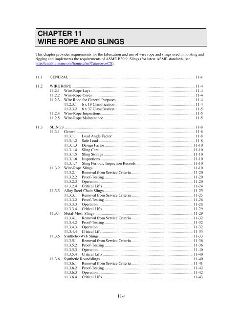
CHAPTER <strong>11</strong><br />
WIRE ROPE AND SLINGS<br />
This chapter provides requirements for the fabrication <strong>and</strong> use of wire rope <strong>and</strong> slings used in hoisting <strong>and</strong><br />
rigging <strong>and</strong> implements the requirements of ASME B30.9, <strong>Slings</strong> (for latest ASME st<strong>and</strong>ards, see<br />
http://catalog.asme.org/home.cfm?Category=CS).<br />
.<br />
<strong>11</strong>.1 GENERAL ...............................................................................................................................<strong>11</strong>-1<br />
<strong>11</strong>.2 WIRE ROPE ............................................................................................................................<strong>11</strong>-4<br />
<strong>11</strong>.2.1 <strong>Wire</strong>-<strong>Rope</strong> Lays.........................................................................................................<strong>11</strong>-4<br />
<strong>11</strong>.2.2 <strong>Wire</strong>-<strong>Rope</strong> Cores .......................................................................................................<strong>11</strong>-4<br />
<strong>11</strong>.2.3 <strong>Wire</strong> <strong>Rope</strong> for General Purposes ...............................................................................<strong>11</strong>-4<br />
<strong>11</strong>.2.3.1 6 x 19 Classification.................................................................................<strong>11</strong>-4<br />
<strong>11</strong>.2.3.2 6 x 37 Classification.................................................................................<strong>11</strong>-5<br />
<strong>11</strong>.2.4 <strong>Wire</strong>-<strong>Rope</strong> Inspections...............................................................................................<strong>11</strong>-5<br />
<strong>11</strong>.2.5 <strong>Wire</strong>-<strong>Rope</strong> Maintenance ............................................................................................<strong>11</strong>-5<br />
<strong>11</strong>.3 SLINGS ...................................................................................................................................<strong>11</strong>-8<br />
<strong>11</strong>.3.1 General.......................................................................................................................<strong>11</strong>-8<br />
<strong>11</strong>.3.1.1 Load Angle Factor ...................................................................................<strong>11</strong>-8<br />
<strong>11</strong>.3.1.2 Safe Load .................................................................................................<strong>11</strong>-8<br />
<strong>11</strong>.3.1.3 Design Factor .........................................................................................<strong>11</strong>-10<br />
<strong>11</strong>.3.1.4 Sling Care...............................................................................................<strong>11</strong>-10<br />
<strong>11</strong>.3.1.5 Sling Storage..........................................................................................<strong>11</strong>-10<br />
<strong>11</strong>.3.1.6 Inspections .............................................................................................<strong>11</strong>-10<br />
<strong>11</strong>.3.1.7 Sling Periodic Inspection Records .........................................................<strong>11</strong>-10<br />
<strong>11</strong>.3.2 <strong>Wire</strong>-<strong>Rope</strong> <strong>Slings</strong>.....................................................................................................<strong>11</strong>-10<br />
<strong>11</strong>.3.2.1 Removal from Service Criteria ..............................................................<strong>11</strong>-20<br />
<strong>11</strong>.3.2.2 Proof-Testing .........................................................................................<strong>11</strong>-20<br />
<strong>11</strong>.3.2.3 Operation................................................................................................<strong>11</strong>-20<br />
<strong>11</strong>.3.2.4 Critical Lifts ...........................................................................................<strong>11</strong>-24<br />
<strong>11</strong>.3.3 Alloy Steel-Chain <strong>Slings</strong>..........................................................................................<strong>11</strong>-25<br />
<strong>11</strong>.3.3.1 Removal from Service Criteria ..............................................................<strong>11</strong>-25<br />
<strong>11</strong>.3.3.2 Proof-Testing .........................................................................................<strong>11</strong>-26<br />
<strong>11</strong>.3.3.3 Operation................................................................................................<strong>11</strong>-28<br />
<strong>11</strong>.3.3.4 Critical Lifts ...........................................................................................<strong>11</strong>-29<br />
<strong>11</strong>.3.4 Metal-Mesh <strong>Slings</strong>...................................................................................................<strong>11</strong>-29<br />
<strong>11</strong>.3.4.1 Removal from Service Criteria ..............................................................<strong>11</strong>-32<br />
<strong>11</strong>.3.4.2 Proof-Testing .........................................................................................<strong>11</strong>-32<br />
<strong>11</strong>.3.4.3 Operation................................................................................................<strong>11</strong>-32<br />
<strong>11</strong>.3.4.4 Critical Lifts ...........................................................................................<strong>11</strong>-33<br />
<strong>11</strong>.3.5 Synthetic-Web <strong>Slings</strong>...............................................................................................<strong>11</strong>-33<br />
<strong>11</strong>.3.5.1 Removal from Service Criteria ..............................................................<strong>11</strong>-36<br />
<strong>11</strong>.3.5.2 Proof-Testing .........................................................................................<strong>11</strong>-36<br />
<strong>11</strong>.3.5.3 Operation................................................................................................<strong>11</strong>-40<br />
<strong>11</strong>.3.5.4 Critical Lifts ...........................................................................................<strong>11</strong>-40<br />
<strong>11</strong>.3.6 Synthetic Roundslings .............................................................................................<strong>11</strong>-40<br />
<strong>11</strong>.3.6.1 Removal from Service Criteria ..............................................................<strong>11</strong>-41<br />
<strong>11</strong>.3.6.2 Proof-Testing .........................................................................................<strong>11</strong>-42<br />
<strong>11</strong>.3.6.3 Operation................................................................................................<strong>11</strong>-42<br />
<strong>11</strong>.3.6.4 Critical Lifts ...........................................................................................<strong>11</strong>-43<br />
<strong>11</strong>-i
DOE-STD-1090-2007<br />
INTENTIONALLY BLANK<br />
<strong>11</strong>-ii
<strong>11</strong>.1 GENERAL<br />
a. The information in this section provides<br />
guidance for safely h<strong>and</strong>ling lifted loads.<br />
Diagrams are used to illustrate hoisting <strong>and</strong><br />
rigging principles <strong>and</strong> good <strong>and</strong> bad rigging<br />
practices. This is not a rigging textbook; the<br />
information should be applied only by<br />
qualified riggers.<br />
b. <strong>Wire</strong> rope <strong>and</strong> slings that have been<br />
irreversibly damaged or removed from<br />
service shall be made unusable for hoisting<br />
<strong>and</strong> rigging operations before being<br />
discarded.<br />
c. Load tables are representative only <strong>and</strong> are<br />
not exact for all materials or all<br />
manufacturers.<br />
d. Prior to rigging a load, determine the weight<br />
of the load:<br />
1. From markings on the load.<br />
2. By weighing, if the load is still on a<br />
truck or railroad car.<br />
3. From drawings or other documentation.<br />
4. By calculation, using the load<br />
dimensions <strong>and</strong> the weights of common<br />
materials in Table <strong>11</strong>-1.<br />
e. Determine the center of gravity of the load<br />
as accurately as possible:<br />
1. From drawings or other documentation.<br />
2. From markings on the load.<br />
3. By calculation.<br />
f. Determine the best method to attach the load<br />
<strong>and</strong> select the appropriate lifting devices<br />
(e.g., wire-rope, steel-chain, metal-mesh, or<br />
synthetic-web slings).<br />
g. Bending a wire rope over a fixed object such<br />
as a pin or a shackle has an effect on the<br />
capacity of the rope: the outside wires <strong>and</strong><br />
DOE-STD-1090-2007<br />
str<strong>and</strong>s of a bend have to stretch farther <strong>and</strong><br />
therefore take a greater percentage of the<br />
load.<br />
h. There is a convenient method for estimating<br />
the efficiency of the rope as it passes over<br />
the bend. This method uses the ratio (R) of<br />
the diameter (D) of the object (sheave, pin,<br />
corner) about which the wire rope is being<br />
bent to the diameter (d) of the rope. The<br />
efficiency of the bend can then be estimated<br />
using the formula shown in Figure <strong>11</strong>-1.<br />
Note that the efficiency decreases quickly as<br />
the ratio of the diameters decreases.<br />
i. Aside from efficiency, there are other<br />
reasons to avoid sharp bends in wire rope<br />
including physical damage to the rope,<br />
reduction of service life, <strong>and</strong> damage to the<br />
object about which the rope is bent.<br />
j. When the ratio of the diameter of the bend<br />
to the nominal rope diameter (D/d ratio) is<br />
small, the strength efficiency factor is lower<br />
than when the D/d ratio is relatively large.<br />
Load tables do not take into account such<br />
factors as abnormal temperatures, excessive<br />
corrosion, <strong>and</strong> vibration.<br />
k. Determine the appropriate ratings of the<br />
device to be used, allowing for:<br />
1. The number of sling legs – Note that a<br />
sling leg completely doubled back on<br />
itself constitutes two sling legs.<br />
2. The angle between the horizontal<br />
surface of the load <strong>and</strong> the sling leg –<br />
The smaller the angle, the smaller the<br />
lifting capacity of the equipment<br />
3. Wear – The reduction in strength of the<br />
equipment due to normal wear.<br />
l. The working load limit (WLL) of wire ropes<br />
<strong>and</strong> slings shall not be exceeded in their as<br />
configured application.<br />
<strong>11</strong>-1 <strong>Chapter</strong> <strong>11</strong><br />
General
Aluminum<br />
Antimony<br />
Bismuth<br />
Brass, cast<br />
Brass, rolled<br />
Copper, cast<br />
Copper, rolled<br />
Gold, 24-carat<br />
Iron, Cast<br />
Iron, wrought<br />
DOE-STD-1090-2007<br />
Table <strong>11</strong>-1. Weights of Common Materials.<br />
Name of Metal Weight<br />
(lb/ft 3 )<br />
Lead, commercial<br />
Mercury, 60 degrees F<br />
Silver<br />
Steel<br />
Tin, cast<br />
Uranium<br />
Zinc<br />
Name of wood<br />
Ash<br />
Beech<br />
Birch<br />
Cedar<br />
Cherry<br />
Chestnut<br />
Cork<br />
Cypress<br />
Ebony<br />
Elm<br />
Fir, Balsam<br />
Hemlock<br />
Maple, Oak<br />
Pine, Poplar<br />
166<br />
418<br />
613<br />
504<br />
523<br />
550<br />
555<br />
1,204<br />
450<br />
480<br />
712<br />
846<br />
655<br />
490<br />
458<br />
1,163<br />
437<br />
<strong>Chapter</strong> <strong>11</strong> <strong>11</strong>-2<br />
General<br />
35<br />
37<br />
40<br />
22<br />
30<br />
26<br />
15<br />
27<br />
71<br />
30<br />
22<br />
31<br />
62<br />
30<br />
Bluestone<br />
Brick, pressed<br />
Brick, common<br />
Name of Metal Weight<br />
(lb/ft 3<br />
Cement, Portl<strong>and</strong> (packed)<br />
Cement, Portl<strong>and</strong> (loose)<br />
Cement, slag (packed)<br />
Cement, slag (loose)<br />
Chalk<br />
Charcoal<br />
Cinder concrete<br />
Clay, ordinary<br />
Coal, hard, solid<br />
Coal, hard, broken<br />
Coal, soft, solid<br />
Coal, soft, broken<br />
Coke, loose<br />
Concrete or stone<br />
Earth, rammed<br />
Granite<br />
Gravel<br />
Lime, quick (ground loose)<br />
Limestone<br />
Marble<br />
Plaster of paris (cast)<br />
S<strong>and</strong><br />
S<strong>and</strong>stone<br />
Shale<br />
Slate<br />
Terra-cotta<br />
Traprock<br />
Water<br />
160<br />
150<br />
125<br />
100-120<br />
70-90<br />
80-100<br />
55-75<br />
156<br />
15-34<br />
<strong>11</strong>0<br />
120-150<br />
93.5<br />
54<br />
84<br />
54<br />
23-32<br />
140-155<br />
90-100<br />
165-170<br />
<strong>11</strong>7-125<br />
53<br />
170<br />
164<br />
80<br />
90-106<br />
151<br />
162<br />
160-180<br />
<strong>11</strong>0<br />
170<br />
65
DOE-STD-1090-2007<br />
Figure <strong>11</strong>-1. Efficiency of wire rope when bent <strong>and</strong> statically loaded to destruction<br />
over sheaves <strong>and</strong> pins of various diameters.<br />
<strong>11</strong>-3 <strong>Chapter</strong> <strong>11</strong><br />
General
<strong>11</strong>.2 WIRE ROPE<br />
<strong>11</strong>.2.1 WIRE-ROPE LAYS<br />
a. In a right-lay rope, the str<strong>and</strong>s twist to the<br />
right around the core like a conventional<br />
screw thread; in a left-lay rope, the str<strong>and</strong>s<br />
twist to the left.<br />
b. A rope has a lang lay when the str<strong>and</strong>s <strong>and</strong><br />
the individual wires have the same lay<br />
direction. When the str<strong>and</strong>s <strong>and</strong> the wires<br />
have an opposite lay direction, the rope has<br />
a regular lay.<br />
c. A st<strong>and</strong>ard wire rope, unless otherwise<br />
stated, is understood to be right regular lay.<br />
With few exceptions, all wire rope is made<br />
right lay. Left-lay rope is a special-purpose<br />
rope.<br />
d. Figure <strong>11</strong>-2 shows ropes with right <strong>and</strong> left<br />
lays combined with regular <strong>and</strong> lang lays.<br />
e. Lay length is the lengthwise distance<br />
measured along a wire rope in which a<br />
str<strong>and</strong> makes one complete revolution about<br />
the rope’s axis.<br />
<strong>11</strong>.2.2 WIRE-ROPE CORES<br />
a. <strong>Wire</strong> rope consists of multistr<strong>and</strong> metal<br />
wires wrapped around a suitable core<br />
material. <strong>Wire</strong>-rope cores are carefully<br />
designed <strong>and</strong> must be precisely<br />
manufactured to close tolerances to ensure a<br />
perfect fit in the rope. The most common<br />
types of cores include the following (see<br />
Figure <strong>11</strong>-3):<br />
1. Fiber Core (FC) or Sisal Core –<br />
Sisalanna is the most common fiber that<br />
is used in the manufacture of wire-rope<br />
cores. In smaller ropes, cotton <strong>and</strong> jute<br />
are sometimes used for the core.<br />
2. Independent <strong>Wire</strong>-<strong>Rope</strong> Core (IWRC) –<br />
The primary function of the core is to<br />
provide adequate support for the<br />
str<strong>and</strong>s. As the name implies, an IWRC<br />
is a separate small-diameter wire rope<br />
that is used as the core for a larger wire<br />
rope. When severe crushing or<br />
flattening of the rope is encountered, an<br />
IWRC is usually specified.<br />
DOE-STD-1090-2007<br />
<strong>Chapter</strong> <strong>11</strong> <strong>11</strong>-4<br />
General<br />
3. Str<strong>and</strong> Core – This type of core has a<br />
single str<strong>and</strong> used as the core. This type<br />
is generally confined to the smaller<br />
ropes as a substitute for IWRC. The<br />
str<strong>and</strong> core may or may not have the<br />
same cross section as the surrounding<br />
str<strong>and</strong>s.<br />
Figure <strong>11</strong>-2. <strong>Wire</strong>-<strong>Rope</strong> lays.<br />
Figure <strong>11</strong>-3. <strong>Wire</strong>-rope cores.<br />
-<br />
<strong>11</strong>.2.3 WIRE ROPE FOR GENERAL<br />
PURPOSES<br />
<strong>11</strong>.2.3.1 6 x 19 Classification<br />
a. Most applications can use a rope from this<br />
classification; it is the most versatile of all<br />
ropes made. Figure <strong>11</strong>-4 shows four<br />
varieties of 6 x 19 wire ropes with FCs <strong>and</strong><br />
IWRCs. Table <strong>11</strong>-2 provides breaking<br />
strengths for 6 x 19 wire ropes with FC <strong>and</strong><br />
IWRC cores.
. The principle types of ropes in this<br />
classification include:<br />
1. 6 x 19F – The most popular <strong>and</strong><br />
versatile of all wire ropes <strong>and</strong> the most<br />
flexible is the 6 x 19F classification.<br />
This rope is considered the perfect<br />
compromise between maximum<br />
abrasion resistance <strong>and</strong> maximum<br />
flexibility.<br />
2. 6 x 16F – Slightly more abrasion<br />
resistant than the 6 x 19F, the 6 x 16F<br />
makes an excellent rope for small<br />
draglines <strong>and</strong> similar uses. The<br />
resistance to wear is gained by a slight<br />
sacrifice in flexibility.<br />
3. 6 x 19 Seale – The 6 x 19 Seale is a<br />
rugged wire rope for applications<br />
involving heavy wear. Car pullers often<br />
use this rope, <strong>and</strong> it is widely used for<br />
slushers <strong>and</strong> drag scrapers.<br />
4. 6 x 19 Warrington – The alternating<br />
large <strong>and</strong> small outer wires make this<br />
rope an all-around performer. The 6 x<br />
19 Warrington is used for generalpurpose<br />
hoisting, churn drills, <strong>and</strong><br />
miscellaneous slings.<br />
<strong>11</strong>.2.3.2 6 x 37 Classification<br />
a. When sheaves <strong>and</strong> drums are fairly small<br />
<strong>and</strong> abrasive conditions are not severe, the<br />
ropes in this classification will show better<br />
performance than the coarser 6 x 19<br />
construction. Under conditions of repeated<br />
bending, they will outlast a 6 x 19 rope;<br />
when abrasion is severe, the small outer<br />
wires quickly show the effect. Figure <strong>11</strong>-5<br />
show three varieties of 6 x 37 wire rope with<br />
FC <strong>and</strong> IWRC cores. Table <strong>11</strong>-3 provides<br />
breaking strengths for 6 x 37 wire ropes with<br />
FC <strong>and</strong> IWRC cores.<br />
b. The principal types of ropes in this<br />
classification include:<br />
1. 6 x 37 2-operation – A 6 x 37 2operation<br />
str<strong>and</strong> has 18 outer wires.<br />
This construction is used on industrial<br />
equipment, for flexible slings, <strong>and</strong> in<br />
miscellaneous hoisting.<br />
DOE-STD-1090-2007<br />
2. 6 x 29F – A 6 x 29F is used for<br />
applications requiring a flexible rope<br />
slightly more resistant to wear than the<br />
6 x 37 2-operation rope.<br />
3. 6 x 41 – A 6 x 41 rope is used widely<br />
for ropes over 1-in. diameter in the 6 x<br />
37 classification.<br />
<strong>11</strong>.2.4 WIRE-ROPE INSPECTIONS<br />
A qualified inspector shall inspect wire ropes at<br />
least annually. Inspection requirements vary<br />
depending on what type of equipment the wire<br />
ropes are used on. Refer to other sections in this<br />
st<strong>and</strong>ard, based on the equipment being used, for<br />
specific inspection requirements.<br />
<strong>11</strong>.2.5 WIRE-ROPE MAINTENANCE<br />
Personnel using wire rope shall ensure proper<br />
care by doing the following:<br />
a. Store rope to prevent damage or<br />
deterioration.<br />
b. Unreel or uncoil rope as recommended by<br />
the rope manufacturer or a qualified person<br />
<strong>and</strong> with care to avoid kinking or inducing a<br />
twist.<br />
c. Before cutting a rope, use some method to<br />
prevent unlaying of the str<strong>and</strong>s. Heataffected<br />
zones of flame cut wire rope shall<br />
not be allowed to bear load.<br />
d. During installation, avoid dragging the rope<br />
in the dirt or around objects that will scrape,<br />
nick, crush, or induce sharp bends.<br />
e. Unless prohibited by other considerations,<br />
maintain rope in a well-lubricated condition.<br />
The object of rope lubrication is to reduce<br />
internal friction <strong>and</strong> to prevent corrosion.<br />
Ensure that lubricant applied as part of a<br />
maintenance program is compatible with the<br />
original lubricant <strong>and</strong> is also a type that does<br />
not hinder visual inspection. Those sections<br />
of rope in contact with sheaves or otherwise<br />
hidden during inspection <strong>and</strong> maintenance<br />
procedures require special attention when<br />
lubricating rope.<br />
<strong>11</strong>-5 <strong>Chapter</strong> <strong>11</strong><br />
General
<strong>Rope</strong><br />
diameter<br />
(in.)<br />
3/16<br />
¼<br />
5/16<br />
3/8<br />
7/16<br />
½<br />
9/16<br />
5/8<br />
¾<br />
7/8<br />
1<br />
1 1/8<br />
1 ¼<br />
1 3/8<br />
1 ½<br />
1 5/8<br />
1 ¾<br />
1 7/8<br />
2<br />
2 ¼<br />
2 ½<br />
2 ¾<br />
DOE-STD-1090-2007<br />
Figure <strong>11</strong>-4. 6 x 19 classification of wire rope.<br />
Table <strong>11</strong>-2. Breaking strength of wire rope (6 x 19 classification).<br />
Weight<br />
(lb. per<br />
ft.) Plow<br />
steel<br />
0.06<br />
0.10<br />
0.16<br />
0.23<br />
0.31<br />
0.40<br />
0.51<br />
0.63<br />
0.90<br />
1.23<br />
1.60<br />
2.03<br />
2.50<br />
3.03<br />
3.60<br />
4.23<br />
4.90<br />
5.63<br />
6.40<br />
8.10<br />
10.00<br />
12.10<br />
Breaking strength<br />
in tons of 2,000 lb.<br />
1.3<br />
2.4<br />
3.8<br />
5.4<br />
7.0<br />
10.0<br />
<strong>11</strong>.7<br />
15.0<br />
21.5<br />
28.3<br />
38.0<br />
48.5<br />
60.0<br />
73.5<br />
88.5<br />
103.0<br />
<strong>11</strong>9.0<br />
138.0<br />
154.0<br />
193.0<br />
235.0<br />
280.0<br />
Improved<br />
plow<br />
steel<br />
1.5<br />
2.7<br />
4.1<br />
6.0<br />
8.0<br />
<strong>11</strong>.0<br />
13.3<br />
16.5<br />
23.8<br />
32.0<br />
41.7<br />
53.0<br />
65.0<br />
81.0<br />
96.0<br />
<strong>11</strong>3.0<br />
130.0<br />
152.0<br />
169.0<br />
210.0<br />
260.0<br />
305.0<br />
<strong>Chapter</strong> <strong>11</strong> <strong>11</strong>-6<br />
General<br />
<strong>Rope</strong><br />
diameter<br />
(in.)<br />
3/16<br />
¼<br />
5/16<br />
3/8<br />
7/16<br />
½<br />
9/16<br />
5/8<br />
¾<br />
7/8<br />
1<br />
1 1/8<br />
1 ¼<br />
1 3/8<br />
1 ½<br />
1 5/8<br />
1 ¾<br />
1 7/8<br />
2<br />
2 ¼<br />
2 ½<br />
2 ¾<br />
Weight<br />
(lb. per<br />
ft.) Plow<br />
steel<br />
0.07<br />
0.<strong>11</strong><br />
0.18<br />
0.25<br />
0.34<br />
0.44<br />
0.56<br />
0.69<br />
0.99<br />
1.35<br />
1.76<br />
2.23<br />
2.75<br />
3.33<br />
3.96<br />
4.65<br />
5.39<br />
6.19<br />
7.04<br />
8.91<br />
<strong>11</strong>.00<br />
13.30<br />
Breaking strength<br />
in tons of 2,000 lb.<br />
1.4<br />
2.6<br />
4.1<br />
5.8<br />
7.5<br />
10.8<br />
12.6<br />
16.1<br />
23.1<br />
30.4<br />
40.8<br />
52.1<br />
64.5<br />
79.0<br />
95.1<br />
<strong>11</strong>1.0<br />
128.0<br />
148.0<br />
166.0<br />
208.0<br />
253.0<br />
301.0<br />
Improved<br />
plow<br />
steel<br />
1.6<br />
2.9<br />
4.4<br />
6.5<br />
8.6<br />
<strong>11</strong>.8<br />
14.3<br />
17.7<br />
25.6<br />
34.4<br />
44.8<br />
57.0<br />
70.4<br />
87.1<br />
103.0<br />
122.0<br />
140.0<br />
163.0<br />
182.0<br />
226.0<br />
280.0<br />
328.0
<strong>Rope</strong><br />
diameter<br />
(in.)<br />
¼<br />
5/16<br />
3/8<br />
7/16<br />
½<br />
9/16<br />
5/8<br />
¾<br />
7/8<br />
1<br />
1 1/8<br />
1 ¼<br />
1 3/8<br />
1 ½<br />
1 5/8<br />
1 ¾<br />
1 7/8<br />
2<br />
2 ¼<br />
2 ½<br />
2 ¾<br />
3<br />
DOE-STD-1090-2007<br />
Figure <strong>11</strong>-5. 6 x 37 classification of wire rope.<br />
Table <strong>11</strong>-3. Breaking strength of wire rope (6 x 37 classification).<br />
Weight<br />
(lb. per<br />
ft.) Plow<br />
steel<br />
0.10<br />
0.16<br />
0.22<br />
0.30<br />
0.39<br />
0.49<br />
0.61<br />
0.87<br />
1.19<br />
1.55<br />
1.96<br />
2.42<br />
2.93<br />
3.49<br />
4.09<br />
4.75<br />
5.45<br />
6.20<br />
7.85<br />
9.69<br />
<strong>11</strong>.72<br />
13.95<br />
Breaking strength<br />
in tons of 2,000 lb.<br />
2.2<br />
3.8<br />
5.0<br />
6.9<br />
9.2<br />
<strong>11</strong>.4<br />
14.5<br />
20.2<br />
27.5<br />
36.0<br />
44.0<br />
55.0<br />
68.5<br />
82.0<br />
96.5<br />
<strong>11</strong>0.0<br />
129.0<br />
142.0<br />
182.0<br />
225.0<br />
269.0<br />
323.0<br />
Improved<br />
plow<br />
steel<br />
2.5<br />
4.0<br />
5.5<br />
7.5<br />
10.0<br />
12.5<br />
16.0<br />
22.2<br />
30.2<br />
39.5<br />
49.0<br />
61.0<br />
74.5<br />
90.0<br />
105.5<br />
121.0<br />
142.0<br />
155.0<br />
201.0<br />
245.0<br />
293.0<br />
353.0<br />
<strong>Rope</strong><br />
diameter<br />
(in.)<br />
¼<br />
5/16<br />
3/8<br />
7/16<br />
½<br />
9/16<br />
5/8<br />
¾<br />
7/8<br />
1<br />
1 1/8<br />
1 ¼<br />
1 3/8<br />
1 ½<br />
1 5/8<br />
1 ¾<br />
1 7/8<br />
2<br />
2 ¼<br />
2 ½<br />
2 ¾<br />
3<br />
Weight<br />
(lb. per<br />
ft.) Plow<br />
steel<br />
0.<strong>11</strong><br />
0.18<br />
0.24<br />
0.33<br />
0.43<br />
0.54<br />
0.67<br />
0.96<br />
1.30<br />
1.1<br />
2.16<br />
2.66<br />
3.22<br />
3.84<br />
4.50<br />
5.23<br />
6.00<br />
6.82<br />
8.64<br />
10.66<br />
12.89<br />
15.35<br />
Breaking strength<br />
in tons of 2,000 lb.<br />
2.4<br />
4.1<br />
5.4<br />
7.4<br />
9.9<br />
12.3<br />
15.6<br />
21.7<br />
29.6<br />
38.7<br />
47.3<br />
59.1<br />
73.6<br />
88.1<br />
104.0<br />
<strong>11</strong>8.0<br />
139.0<br />
153.0<br />
196.0<br />
242.0<br />
289.0<br />
347.0<br />
Improved<br />
plow<br />
steel<br />
2.7<br />
4.3<br />
5.9<br />
8.1<br />
10.8<br />
13.4<br />
17.2<br />
23.9<br />
32.5<br />
42.5<br />
52.7<br />
65.6<br />
80.1<br />
96.7<br />
<strong>11</strong>3.0<br />
130.0<br />
153.0<br />
167.0<br />
216.0<br />
263.0<br />
315.0<br />
379.0<br />
<strong>11</strong>-7 <strong>Chapter</strong> <strong>11</strong><br />
General
<strong>11</strong>.3 SLINGS<br />
<strong>11</strong>.3.1 GENERAL<br />
a. <strong>Slings</strong> shall have a minimum design factor<br />
appropriate to the type of material as<br />
specified in the appropriate section.<br />
Features that affect the rated capacity of the<br />
sling <strong>and</strong> that shall be considered in<br />
calculating the design factor are:<br />
1. Nominal breaking strength of material<br />
from which it is constructed.<br />
2. Splicing or end-attachment.<br />
3. Number of parts in the sling.<br />
4. Type of hitch (e.g., straight pull, choker<br />
hitch, or basket hitch).<br />
5. Angle of loading <strong>and</strong> load center of<br />
gravity.<br />
6. Diameter of curvature around which the<br />
sling is bent.<br />
b. The center of gravity of an object is a point<br />
around which the entire weight may be<br />
concentrated. To make a level lift, the crane<br />
hook or point of suspension must be directly<br />
above this point. While slight variations are<br />
usually permissible, if the crane hook is too<br />
far to one side of the center of gravity,<br />
dangerous tilting will result <strong>and</strong> should be<br />
corrected at once. For this reason, when the<br />
center of gravity is closer to one point of the<br />
sling attachment than to the other, the slings<br />
must be of unequal length. Sling stresses<br />
<strong>and</strong> sling angles will also be unequal (see<br />
Figure <strong>11</strong>-6).<br />
c. Rigging shall be configured such that slings<br />
do not reeve or slip through the hook. To<br />
attach the load, locate the center of gravity,<br />
position the crane hook directly above the<br />
center of gravity, <strong>and</strong> then rig the load so<br />
that it will lift level <strong>and</strong> true.<br />
DOE-STD-1090-2007<br />
<strong>Chapter</strong> <strong>11</strong> <strong>11</strong>-8<br />
General<br />
<strong>11</strong>.3.1.1 Load Angle Factor<br />
a. The following is an example of selecting a<br />
sling using the load angle factors shown in<br />
Figure <strong>11</strong>-7.<br />
1. Load = 1,000 lb.<br />
2. Sling = 2-legged bridle.<br />
3. Angle with horizontal = 45 degrees.<br />
4. Load angle factor from Figure<br />
<strong>11</strong>-7 = 1.414<br />
b. Each of the two legs would lift 500 lb if a<br />
vertical lift were made. However, there is a<br />
45 sling angle involved. Therefore, the 500lb<br />
load would be multiplied by the loadangle<br />
factor in the chart, giving a total of<br />
707 lb (500 lb x 1.414) tension in each sling<br />
leg. Each sling leg, therefore, must have a<br />
rated capacity of at least 707 lb.<br />
<strong>11</strong>.3.1.2 Safe Load<br />
a. The rated capacity or working load limit<br />
(WLL) of a sling varies depending on the<br />
type of hitch. The rated capacity tables in<br />
this section show the applications for which<br />
the various safe loads apply when the slings<br />
are new. All ratings are in pounds (lbs).<br />
b. Figures <strong>11</strong>-8 <strong>and</strong> <strong>11</strong>-9 provide information<br />
for determining the total rated capacity of 3leg<br />
slings so as not to introduce a working<br />
load in direct tension in any leg greater than<br />
that permitted. Two legs should be<br />
considered to carry the load because in<br />
normal lifting practice, the load will not be<br />
uniformly distributed on all legs. If rigging<br />
techniques, verified by a qualified rigger,<br />
ensure that the load is evenly distributed<br />
then full use of three legs is allowed.<br />
Special rigging techniques verified by a<br />
qualified engineer shall be required to prove<br />
that a load is evenly distributed over four or<br />
more sling legs.
DOE-STD-1090-2007<br />
Figure <strong>11</strong>-6. Balancing Loads<br />
Figure <strong>11</strong>-7. Relationship of load angle <strong>and</strong> lifting efficiency.<br />
<strong>11</strong>-9 <strong>Chapter</strong> <strong>11</strong><br />
General
<strong>11</strong>.3.1.3 Design Factor<br />
In general, a design factor of 5:1 is maintained<br />
throughout this section with the exception of<br />
alloy steel chain slings. Also, certain sling<br />
fittings, such as hooks (which will deform<br />
beyond usefulness before breaking) cannot be<br />
assigned a definite numerical design factor. In<br />
such cases, suitable safe loads are listed, based<br />
on wide experience <strong>and</strong> sound engineering<br />
practice.<br />
<strong>11</strong>.3.1.4 Sling Care<br />
Proper care <strong>and</strong> usage are essential for maximum<br />
service <strong>and</strong> safety. <strong>Wire</strong>-rope slings shall be<br />
protected from sharp bends <strong>and</strong> cutting edges by<br />
means of corner saddles, burlap padding, or<br />
wood blocking. Overloading shall be avoided,<br />
as shall sudden dynamic loading that can build<br />
up a momentary overload sufficient to break the<br />
sling.<br />
<strong>11</strong>.3.1.5 Sling Storage<br />
Personnel using slings shall ensure that they are<br />
stored properly as follows:<br />
a. <strong>Slings</strong> should be stored in racks (preferably<br />
vertical) <strong>and</strong> in designated locations when<br />
not in use. Do not store slings in a location<br />
where they will be subjected to mechanical<br />
damage, corrosive action, moisture, extreme<br />
heat, or kinking. <strong>Slings</strong> may require<br />
segregated storage as determined on a caseby-case<br />
basis.<br />
b. Before storage <strong>and</strong> periodically during<br />
storage, wipe slings clean to remove as<br />
much dirt <strong>and</strong> abrasive grit as possible <strong>and</strong><br />
relubricate wire rope <strong>and</strong> chain slings to<br />
extend their useful life. Chains should not<br />
be lubricated when in use.<br />
c. Do not store metal-mesh slings in areas<br />
where the temperature exceeds 550 degrees<br />
F (288 degrees C) or 200 degrees F (93<br />
degrees C) if elastomer covered.<br />
d. Do not store synthetic-web slings where the<br />
temperature exceeds 200 degrees F (93<br />
degrees C).<br />
DOE-STD-1090-2007<br />
<strong>Chapter</strong> <strong>11</strong> <strong>11</strong>-10<br />
General<br />
<strong>11</strong>.3.1.6 Inspections<br />
a. Sling users shall visually inspect all slings<br />
each day they are used or prior to use if the<br />
sling has not been in regular service (records<br />
are not required). In addition, a periodic<br />
inspection shall be made at least annually by<br />
a qualified inspector. More frequent<br />
intervals for periodic inspections should be<br />
established if necessary as determined by a<br />
qualified person based upon:<br />
1. Frequency of sling use.<br />
2. Severity of service conditions.<br />
3. Nature of lifts being made.<br />
4. Experience gained on the service life of<br />
slings used in similar circumstances.<br />
b. Users shall carefully note any deterioration<br />
that could result in an appreciable loss of<br />
original strength <strong>and</strong> determine whether<br />
further use of the sling would constitute a<br />
safety hazard. Removal from service<br />
criteria are provided for each type of sling in<br />
their respective sections.<br />
<strong>11</strong>.3.1.7 Sling Periodic Inspection<br />
Records<br />
Individual site programs shall describe how<br />
inspections are recorded. These records may<br />
include an external coded mark on the individual<br />
sling tag (e.g. date, annually changed color<br />
stripe, etc.) indicating both periodicity <strong>and</strong> the<br />
satisfactory completion of the required<br />
inspection, or a written record as acceptable<br />
documentation.<br />
<strong>11</strong>.3.2 WIRE-ROPE SLINGS<br />
a. In general, wire-rope slings are made up of 6<br />
x 19 or 6 x 37 classification wire rope.<br />
Rotation-resistant wire rope shall not be<br />
used for wire-rope slings. Different kinds of<br />
slings have been developed for specific<br />
purposes. These are divided into different<br />
groups or types as follows:<br />
1. Endless-loop slings (grommet<br />
construction) <strong>and</strong> single-part slings with<br />
single-rope legs, double-rope legs, or<br />
multiple-part rope legs.
2. Two-leg bridle slings with single-rope<br />
legs, equalizing double-rope legs, or<br />
multiple-part tope legs.<br />
3. Three-leg bridle slings.<br />
4. Four-leg bridle slings.<br />
5. Special slings <strong>and</strong> combinations.<br />
b. The total load that can be safely lifted with<br />
slings depends on the rating of the slings <strong>and</strong><br />
the manner in which they are attached to the<br />
load. Consult Tables <strong>11</strong>-4 through <strong>11</strong>-9 <strong>and</strong><br />
Figure <strong>11</strong>-10.<br />
c. Braided slings are made by braiding<br />
ordinary wire ropes together, thus making<br />
them more flexible than wire-rope slings.<br />
The size of a braided sling is determined by<br />
the diameter of one wire rope <strong>and</strong> the<br />
number of ropes in the cross section of the<br />
slings.<br />
DOE-STD-1090-2007<br />
d. The design factor for wire-rope slings shall<br />
be a minimum of 5:1 based upon breaking<br />
strength.<br />
e. When a wire rope sling is used in a choker<br />
hitch, the normal angle formed in the rope<br />
body as it passes through the choking eye is<br />
120 degrees or greater [do not confuse the<br />
choke angle with the angle of inclination of<br />
the load (see Figure <strong>11</strong>-10)]. Rated load in<br />
load capacity Tables <strong>11</strong>-4 through <strong>11</strong>-9 are<br />
for angles of 120 degrees or greater. For<br />
smaller angles, reduce the rated load to the<br />
percentages given in Figure <strong>11</strong>-10.<br />
<strong>11</strong>-<strong>11</strong> <strong>Chapter</strong> <strong>11</strong><br />
General
DOE-STD-1090-2007<br />
Figure <strong>11</strong>-8. Determination of capacity—3-leg bridle sling.<br />
Figure <strong>11</strong>-9. Determination of capacity—4-leg bridle sling.<br />
Figure <strong>11</strong>-8. Determination of capacity – 3-leg bridle sling.<br />
Figure <strong>11</strong>-9. Determination of capacity – 4-leg bridle sling.<br />
<strong>Chapter</strong> <strong>11</strong> <strong>11</strong>-12<br />
General
Notes:<br />
Dia. in<br />
inches<br />
DOE-STD-1090-2007<br />
Table <strong>11</strong>-4. Load capacity of wire-rope slings.<br />
H<strong>and</strong> tuck splice (IWRC) in pounds Design Factor = 5:1<br />
Vertical<br />
Choker<br />
Basket or<br />
two legs<br />
Dia. in<br />
inches<br />
¼ 1,100 820 2,200 1,800 1,500 1,100 ¼<br />
5/16 1,600 1,280 3,200 2,800 2,200 1,600 5/16<br />
3/8 2,400 1,840 4,800 4,000 3,200 2,400 3/8<br />
7/16 3,000 2,400 6,000 5,400 4,400 3,000 7/16<br />
½ 4,000 3,200 8,000 6,800 5,600 4,000 ½<br />
9/16 5,000 4,000 10,000 8,600 7,000 5,000 9/16<br />
5/8 6,000 5,000 12,000 10,400 8,400 6,000 5/8<br />
¾ 8,400 7,200 16,800 14,600 <strong>11</strong>,800 8,400 ¾<br />
7/8 <strong>11</strong>,000 9,600 22,000 19,200 15,600 <strong>11</strong>,000 7/8<br />
1 14,000 12,600 28,000 24,000 20,000 14,000 1<br />
1 1/8 18,000 15,800 36,000 32,000 26,000 18,000 1 1/8<br />
*1 ¼ 22,000 19,400 44,000 36,000 30,000 22,000 *1 ¼<br />
*1 3/8 26,000 24,000 52,000 44,000 36,000 26,000 *1 3/8<br />
*1 ½ 32,000 28,000 64,000 52,000 42,000 32,000 *1 ½<br />
*1 5/8 36,000 32,000 72,000 62,000 50,000 36,000 *1 5/8<br />
*1 ¾ 42,000 38,000 84,000 70,000 58,000 42,000 *1 ¾<br />
*2 56,000 48,000 <strong>11</strong>2,000 92,000 74,000 56,000 *2<br />
<strong>Wire</strong> <strong>Rope</strong>/6 x 19 <strong>and</strong> *6 x 37 IPS IWRC<br />
(1) These values only apply when the D/d ratio is 25 or greater (choker <strong>and</strong> basket hitches)<br />
D = Diameter of curvature around which the body of the sling is bent<br />
d = Diameter of rope<br />
(2) Choker hitch values apply only to choke angles greater than 120 degrees.<br />
<strong>11</strong>-13 <strong>Chapter</strong> <strong>11</strong><br />
General
Notes:<br />
Dia. in<br />
inches<br />
DOE-STD-1090-2007<br />
Table <strong>11</strong>-5. Load capacity of wire-rope slings.<br />
H<strong>and</strong> tuck splice (Fiber Core) in pounds Design Factor = 5:1<br />
Vertical<br />
Choker<br />
Basket or<br />
two legs<br />
<strong>Chapter</strong> <strong>11</strong> <strong>11</strong>-14<br />
General<br />
Dia. in<br />
inches<br />
¼ 980 760 1,960 1,700 1,400 980 ¼<br />
5/16 1,500 1,200 3,040 2,600 2,200 1,500 5/16<br />
3/8 2,200 1,700 4,400 3,600 3,000 2,200 3/8<br />
7/16 2,800 2,400 5,600 5,000 4,000 2,800 7/16<br />
½ 3,600 3,000 7,200 6,400 5,200 3,600 ½<br />
9/16 4,600 3,800 9,200 8,000 6,400 4,600 9/16<br />
5/8 5,600 4,600 <strong>11</strong>,200 9,600 8,000 5,600 5/8<br />
¾ 7,800 6,600 15,600 13,600 <strong>11</strong>,000 7,800 ¾<br />
7/8 10,400 9,000 20,080 17,800 14,600 10,400 7/8<br />
1 13,400 <strong>11</strong>,800 26,800 22,000 18,800 13,400 1<br />
1 1/8 16,800 14,800 33,600 28,000 24,000 16,800 1 1/8<br />
*1 ¼ 20,000 18,000 40,000 34,000 28,000 20,000 *1 ¼<br />
*1 3/8 24,000 22,000 48,000 42,000 34,000 24,000 *1 3/8<br />
*1 ½ 30,000 26,000 60,000 52,000 42,000 30,000 *1 ½<br />
*1 5/8 34,000 30,000 68,000 58,000 48,000 34,000 *1 5/8<br />
*1 ¾ 40,000 34,000 80,000 70,000 56,000 40,000 *1 ¾<br />
*2 52,000 44,000 104,000 90,000 74,000 52,000 *2<br />
<strong>Wire</strong> <strong>Rope</strong>/6 x 19 <strong>and</strong> *6 x 37 IPS FC<br />
(1) These values only apply when the D/d ratio is 25 or greater (choker <strong>and</strong> basket hitches)<br />
D = Diameter of curvature around which the body of the sling is bent<br />
d = Diameter of rope<br />
(2) Choker hitch values apply only to choke angles greater than 120 degrees.
Notes:<br />
Dia. in<br />
inches<br />
DOE-STD-1090-2007<br />
Table <strong>11</strong>-6. Load capacity of wire-rope slings.<br />
Mechanical splice (IWRC) in pounds Design Factor = 5:1<br />
Vertical<br />
Choker<br />
Basket or<br />
two legs<br />
Dia. in<br />
inches<br />
¼ 1,100 840 2,200 1,940 1,580 1,100 ¼<br />
5/16 1,700 1,300 3,400 3,000 2,400 1,700 5/16<br />
3/8 2,400 1,860 4,800 4,200 3,600 2,400 3/8<br />
7/16 3,400 2,500 3,800 5,800 4,800 3,400 7/16<br />
½ 4,400 3,200 8,800 7,600 6,200 4,400 ½<br />
9/16 5,500 4,200 <strong>11</strong>,000 9,600 7,700 5,500 9/16<br />
5/8 6,800 5,000 13,600 <strong>11</strong>,800 9,600 6,800 5/8<br />
¾ 9,700 7,200 19,400 16,800 13,600 9,700 ¾<br />
7/8 13,000 9,800 26,000 22,000 18,300 13,000 7/8<br />
1 17,000 12,800 34,000 30,000 24,000 17,000 1<br />
1 1/8 20,000 15,600 40,000 36,000 30,000 20,000 1 1/8<br />
*1 ¼ 25,000 18,400 50,000 42,000 34,000 25,000 *1 ¼<br />
*1 3/8 30,000 24,000 60,000 52,000 42,000 30,000 *1 3/8<br />
*1 ½ 36,000 28,000 72,000 64,000 50,000 32,000 *1 ½<br />
*1 5/8 42,000 32,000 84,000 70,000 58,000 42,000 *1 5/8<br />
*1 ¾ 50,000 38,000 100,000 82,000 66,000 50,000 *1 ¾<br />
*2 64,000 48,000 128,000 106,000 86,000 64,000 *2<br />
(1) These values only apply when the D/d ratio is 25 or greater (choker <strong>and</strong> basket hitches)<br />
D = Diameter of curvature around which the body of the sling is bent<br />
d = Diameter of rope<br />
(2) Choker hitch values apply only to choke angles greater than 120 degrees.<br />
<strong>11</strong>-15 <strong>Chapter</strong> <strong>11</strong><br />
General
Notes:<br />
Dia. in<br />
inches<br />
DOE-STD-1090-2007<br />
Table <strong>11</strong>-7. Load capacity of wire-rope slings.<br />
8-part braided rope in pounds Design Factor = 5:1<br />
Vertical<br />
Choker<br />
Basket or<br />
two legs<br />
<strong>Chapter</strong> <strong>11</strong> <strong>11</strong>-16<br />
General<br />
Dia. in<br />
inches<br />
*1/8 1,900 1,400 3,200 2,600 1,900 *1/8<br />
*3/16 4,200 3,000 7,200 5,800 4,200 *3/16<br />
3/16 3,400 2,600 6,000 4,800 3,400 3/16<br />
¼ 6,200 4,600 10,600 8,600 6,200 ¼<br />
5/16 9,600 7,200 16,600 13,400 9,600 5/16<br />
3/8 13,600 10,200 24,000 19,400 13,600 3/8<br />
7/16 18,000 13,800 32,000 26,000 18,600 7/16<br />
1/2 24,000 18,000 42,000 34,000 24,000 1/2<br />
9/16 30,000 22,000 52,000 42,000 30,000 9/16<br />
5/8 38,000 28,000 64,000 52,000 38,000 5/8<br />
¾ 54,000 40,000 92,000 76,000 54,000 ¾<br />
7/8 72,000 54,000 124,000 102,000 72,000 7/8<br />
1 94,000 70,000 162,000 132,000 94,000 1<br />
<strong>Wire</strong> <strong>Rope</strong>/6 x 19 IPS <strong>and</strong> *7 x 7 Galvanized Aircraft Grade<br />
(1) These values only apply when the D/d ratio is 25 or greater (choker <strong>and</strong> basket hitches)<br />
D = Diameter of curvature around which the body of the sling is bent<br />
d = Diameter of rope<br />
(2) Choker hitch values apply only to choke angles greater than 120 degrees.
Dia. in<br />
inches<br />
Vertical<br />
DOE-STD-1090-2007<br />
Table <strong>11</strong>-8. Load capacity of wire-rope slings.<br />
Cable laid grommet-h<strong>and</strong> tucked in pounds Design Factor = 5:1<br />
Choker<br />
Basket or<br />
two legs<br />
60<br />
degrees<br />
45<br />
degrees<br />
30<br />
degrees<br />
Dia. in<br />
inches<br />
*3/8 2,600 1,900 5,000 4,400 3,600 2,600 *3/8<br />
*9/16 5,600 4,200 <strong>11</strong>,200 9,800 8,000 5,600 *9/16<br />
*5/8 7,800 6,000 15,800 13,600 <strong>11</strong>,200 6,800 *5/8<br />
¾ 10,200 7,600 20,000 17,600 14,400 10,200 ¾<br />
15/16 15,800 <strong>11</strong>,800 32,000 28,000 22,000 15,800 15/16<br />
1 1/8 22,000 16,800 44,000 38,000 32,000 22,000 1 1/8<br />
1 5/16 30,000 22,000 60,000 52,000 42,000 30,000 1 5/16<br />
1 ½ 38,000 28,000 78,000 66,000 54,000 38,000 1 ½<br />
1 <strong>11</strong>/16 48,000 36,000 98,000 84,000 68,000 48,000 1 <strong>11</strong>/16<br />
1 7/8 60,000 44,000 120,000 104,000 84,000 60,000 1 7/8<br />
2 ¼ 84,000 62,000 168,000 146,000 <strong>11</strong>8,000 84,000 2 ¼<br />
2 5/8 <strong>11</strong>2,000 84,000 224,000 194,000 158,000 <strong>11</strong>2,000 2 5/8<br />
Notes:<br />
3 144,000 108,000 286,000 248,000 202,000 144,000 3<br />
<strong>Wire</strong> <strong>Rope</strong>/*7 x 6 x 7 <strong>and</strong> 7 x 6 x 19 IPS IWRC<br />
(1) These values only apply when the D/d ratio is 10 or greater (choker <strong>and</strong> basket hitches)<br />
D = Diameter of curvature around which the body of the sling is bent<br />
d = Diameter of rope<br />
(2) Choker hitch values apply only to choke angles greater than 120 degrees.<br />
<strong>11</strong>-17 <strong>Chapter</strong> <strong>11</strong><br />
General
Dia. in<br />
inches<br />
Vertical<br />
DOE-STD-1090-2007<br />
Table <strong>11</strong>-9. Load capacity of wire-rope slings.<br />
Str<strong>and</strong> laid grommet-h<strong>and</strong> tucked in pounds Design Factor = 5:1<br />
Choker<br />
Basket or<br />
two legs<br />
60<br />
degrees<br />
<strong>Chapter</strong> <strong>11</strong> <strong>11</strong>-18<br />
General<br />
45<br />
degrees<br />
30<br />
degrees<br />
Dia. in<br />
inches<br />
¼ 1,840 1,320 3,600 3,200 2,600 1,840 ¼<br />
3/8 4,000 3,000 8,000 7,000 5,800 4,000 3/8<br />
½ 7,000 5,200 14,000 12,200 10,000 7,000 ½<br />
5/8 10,800 8,000 22,000 18,800 15,200 10,800 5/8<br />
¾ 15,200 <strong>11</strong>,400 30,000 26,000 22,000 15,200 ¾<br />
7/8 20,000 15,200 40,000 34,000 28,000 20,000 7/8
DOE-STD-1090-2007<br />
Reprinted from ASME B30.9-2006 by permission of The American Society of Mechanical Engineers. All rights reserved.<br />
Figure <strong>11</strong>-10. Choker hitch rated capacity adjustment.<br />
<strong>11</strong>-19 <strong>Chapter</strong> <strong>11</strong><br />
General
<strong>11</strong>.3.2.1 Removal from Service Criteria<br />
a. <strong>Wire</strong> rope slings shall be immediately<br />
removed from service if any of the following<br />
conditions are present:<br />
1. Missing or illegible sling identification<br />
2. Broken wires<br />
i. For str<strong>and</strong>-laid <strong>and</strong> single-part slings,<br />
ten r<strong>and</strong>omly distributed broken wires<br />
in one rope lay, or five broken wires in<br />
one str<strong>and</strong> in one rope lay.<br />
ii. For cable-laid slings, 20 broken wires<br />
per lay.<br />
iii. For six-part braided slings, 20 broken<br />
wires per braid.<br />
iv. For eight-part braided slings, 40<br />
broken wires per braid<br />
3. Severe localized abrasion or scraping<br />
4. Kinking, crushing, birdcaging, or any<br />
other damage resulting in damage to the<br />
rope structure<br />
5. Evidence of heat damage<br />
6. End attachments that are cracked,<br />
deformed, or worn to the extent that the<br />
strength of the sling is substantially<br />
affected<br />
7. Severe corrosion of the rope, end<br />
attachments, or fittings<br />
8. For hooks, removal criteria as stated in<br />
Section 12.2.<br />
9. Other conditions, including visible<br />
damage, that cause doubt as to the<br />
continued use of the sling<br />
<strong>11</strong>.3.2.2 Proof-Testing<br />
a. All swaged socket <strong>and</strong> poured socket sling<br />
assemblies shall be proof-tested to the wire<br />
DOE-STD-1090-2007<br />
<strong>Chapter</strong> <strong>11</strong> <strong>11</strong>-20<br />
General<br />
rope or fitting manufacturer’s<br />
recommendations but in no case greater than<br />
50 percent of the component wire rope’s or<br />
structural str<strong>and</strong>’s nominal strength. All<br />
other sling assemblies shall be proof-tested<br />
when specified by the purchaser.<br />
b. As a minimum, the proof load shall be equal<br />
to the rated capacity but shall not exceed:<br />
1. 125 percent of the vertical rated capacity<br />
for single-let, h<strong>and</strong>-tucked slings.<br />
2. 200 percent of the vertical rated capacity<br />
for mechanical-splice single-leg slings<br />
<strong>and</strong> endless slings.<br />
c. The proof-load for multiple-leg bridle slings<br />
assemblies shall be applied to the individual<br />
leg <strong>and</strong> shall be in accordance with paragraph<br />
a. <strong>and</strong> b. as applicable.<br />
d. Master links to which multiple-leg slings are<br />
connected shall be proof-loaded to 200<br />
percent times the force applied by the<br />
combined legs.<br />
e. Welded end attachments shall not be used<br />
unless proof-tested at 2 times rated capacity<br />
prior to initial use.<br />
f. Test loads described above shall be accurate<br />
to within –5 percent, +0 percent of stipulated<br />
values. A written letter of certification by the<br />
manufacturer or a pull test witnessed <strong>and</strong><br />
certified in writing by a qualified person is<br />
acceptable.<br />
<strong>11</strong>.3.2.3 Operation<br />
a. The following shall apply to all personnel<br />
who use wire-rope slings:<br />
1. Start <strong>and</strong> stop slowly; sudden starts <strong>and</strong><br />
stops dramatically increase the stresses in<br />
hoist ropes <strong>and</strong> slings. Lift slowly until<br />
the load is suspended to minimize<br />
swinging.
2. Loads shall be set on blocks. Do not pull<br />
a sling from under a load that is resting<br />
on the sling.<br />
3. Ensure that wire-rope slings are<br />
protected against weather, chemicals,<br />
solvents, <strong>and</strong> high temperatures.<br />
4. Permanently remove from service fibercore<br />
rope slings that have been exposed<br />
to temperatures in excess of 180 degrees<br />
F (82 degrees C).<br />
5. When wire rope slings of any grade are<br />
to be used at temperatures above 400<br />
degrees F (204 degrees C) or below -60<br />
degrees F (-51 degrees C), the sling<br />
manufacturer should be consulted.<br />
6. Extremely low temperatures (less than 0<br />
degrees F) may cause brittle fractures.<br />
Under these conditions, sudden loading<br />
should be avoided <strong>and</strong> the rope should be<br />
carefully observed while the load is<br />
being applied.<br />
7. Do not use knotted slings.<br />
8. Do not use single-let wire-rope slings<br />
unless proper precautions are taken to<br />
prevent suspended loads from rotating.<br />
9. Rigging shall be configured such that<br />
slings do not reeve or slip through the<br />
hook.<br />
10. Do not make a complete turn of wire<br />
rope around the crane hook.<br />
<strong>11</strong>. Use protector pads or blocking at sharp<br />
corners.<br />
12. Keep h<strong>and</strong>s <strong>and</strong> fingers out of the area<br />
between the sling <strong>and</strong> the load.<br />
13. Ensure that the weight of the load is<br />
within the rated capacity of the sling.<br />
14. Do not use damaged slings.<br />
15. Ensure that all personnel st<strong>and</strong> clear of<br />
the suspended load.<br />
DOE-STD-1090-2007<br />
16. Avoid shock loading.<br />
17. In a basket hitch, ensure that the load is<br />
balanced to prevent slippage.<br />
18. Avoid h<strong>and</strong>ling hot material with wirerope<br />
slings.<br />
19. Use shackles or adjustable choker hooks<br />
when making choker hitches.<br />
20. Store slings on racks away from moisture<br />
<strong>and</strong> acids when not in use.<br />
21. Ensure that damaged wire-rope slings are<br />
rendered unusable, removed from<br />
service, discarded, <strong>and</strong> replaced with<br />
new slings.<br />
22. Before use <strong>and</strong> before storage, check<br />
wire-rope slings for:<br />
i. Broken or cut wires or str<strong>and</strong>s.<br />
ii. Rust or corrosion.<br />
iii. Kinks.<br />
iv. Broken seizing wire.<br />
v. Damage to swaged fittings.<br />
vi. Other signs of damage or abuse.<br />
23. The capacity of wire-rope slings is<br />
derated by the manufacturer by applying<br />
the efficiency factors such as those given<br />
in Figure <strong>11</strong>-<strong>11</strong>.<br />
24. Do not use wire-rope clips to fabricate<br />
wire-rope slings except where the<br />
application of slings prevents the use of<br />
prefabricated slings <strong>and</strong> where the<br />
specific application is designed by a<br />
qualified person. Fabrication of wire<br />
rope slings for construction applications<br />
is also prohibited (See Section 15.4.2).<br />
<strong>Slings</strong> made with wire rope clips should<br />
not be used as a choker hitch (see<br />
Figures <strong>11</strong>-12 <strong>and</strong> <strong>11</strong>-13).<br />
<strong>11</strong>-21 <strong>Chapter</strong> <strong>11</strong><br />
General
25. If wire-rope clips are used to fabricate<br />
slings, the capacity of the sling shall be<br />
derated in accordance with the clip<br />
manufacturer’s recommendations.<br />
Manufacturer’s recommendations shall<br />
also be followed with regard to clip<br />
spacing, number of clips, <strong>and</strong> torque<br />
values.<br />
26. <strong>Wire</strong> rope clips used to fabricate wire<br />
rope slings shall be of drop-forged steel.<br />
Malleable cast iron clips shall not be<br />
used.<br />
27. <strong>Wire</strong> rope clips attached with U-bolts<br />
shall have the U-bolt over the dead end<br />
of the rope <strong>and</strong> the live rope resting in<br />
the clip saddle. Clips shall be tightened<br />
evenly to the recommended torque.<br />
After the initial load is applied to the<br />
rope, the clip nuts shall be retightened to<br />
the recommended torque to compensate<br />
for any decrease in rope diameter caused<br />
by the load. <strong>Rope</strong> clip nuts should be<br />
retightened periodically to compensate<br />
for any further decrease in rope diameter<br />
during usage.<br />
28. At a minimum, wire-rope slings shall be<br />
marked with the following information:<br />
i. Name of trademark of manufacturer<br />
DOE-STD-1090-2007<br />
<strong>Chapter</strong> <strong>11</strong> <strong>11</strong>-22<br />
General<br />
ii. Rated capacity for the type of<br />
hitch(es)<br />
iii. Diameter or size<br />
29. Sling identification shall be maintained by<br />
the user so as to be legible during the life<br />
of the sling.<br />
30. <strong>Slings</strong> made of rope with 6 x 19 <strong>and</strong> 6 x 37<br />
construction <strong>and</strong> cable-laid slings shall<br />
have a minimum clear length of rope 10<br />
times the rope diameter between splices,<br />
sleeves, or end fittings.<br />
31. Braided slings shall have a minimum clear<br />
length of rope 40 times the component<br />
(individual) rope diameter between the<br />
loops or end fittings.<br />
32. Grommets <strong>and</strong> endless slings shall have a<br />
minimum circumferential length of 96<br />
times the body diameter of the grommet or<br />
endless sling.<br />
33. Other configurations may be used provided<br />
a qualified engineer provides a documented<br />
evaluation, including a destructive pull test<br />
in the configuration to be used, as well as<br />
use limitations. Minimum design factor of<br />
5:1 shall be maintained.
Note that the base of the clip bears<br />
against the live end of the wire rope,<br />
while the “U” of the bolt presses against<br />
the dead end.<br />
Figure <strong>11</strong>-12. <strong>Wire</strong>-rope clips – right<br />
Way.<br />
DOE-STD-1090-2007<br />
Figure <strong>11</strong>-<strong>11</strong>. <strong>Wire</strong>-rope fastenings.<br />
The “U” of the clips shall not bear<br />
against the live end of the wire rope<br />
because of the possibility of the rope<br />
being kinked or crushed.<br />
Figure <strong>11</strong>-13. <strong>Wire</strong>-rope clips –<br />
wrong way.<br />
<strong>11</strong>-23 <strong>Chapter</strong> <strong>11</strong><br />
General
<strong>11</strong>.3.2.4 Critical Lifts<br />
See chapter 2, “Critical Lifts,” for critical lift<br />
requirements.<br />
1. All provisions of paragraph <strong>11</strong>.3.2.3.a<br />
also shall apply to critical lifts.<br />
2. <strong>Wire</strong>-rope slings used for critical-lift<br />
service shall have an initial proof test. If<br />
proof testing cannot be verified, the wirerope<br />
sling(s) shall be proof tested before<br />
being used to make a critical lift. As a<br />
minimum, the proof load shall be equal<br />
to the rated capacity, but shall not<br />
exceed:<br />
i. The wire rope or fitting<br />
manufacturers’ recommendations,<br />
but in no case greater than 50<br />
percent of the component wire<br />
rope’s or structural str<strong>and</strong>s’ nominal<br />
strength, for all swaged socket <strong>and</strong><br />
poured socket sling assemblies.<br />
ii. 125 percent of the vertical rated<br />
capacity of single-leg, h<strong>and</strong>-tucked<br />
slings.<br />
iii. 200 percent of the vertical rated<br />
capacity for mechanical-spliced<br />
single-let slings <strong>and</strong> endless slings.<br />
iv. The proof-load for multiple-leg<br />
bridle slings assemblies shall be<br />
applied to the individual leg <strong>and</strong><br />
shall be in accordance with<br />
paragraph I, ii, <strong>and</strong> iii, as applicable.<br />
v. Master links to which multiple-leg<br />
slings are connected shall be proofloaded<br />
to 200 percent times the force<br />
applied by the combined legs.<br />
vi. Test weights shall be accurate to<br />
within –5 percent, +0 percent of<br />
stipulated values.<br />
3. <strong>Wire</strong>-rope sling eyes with thimbles shall<br />
be made with a thimble having a ratio of<br />
thimble diameter (D) to rope diameter<br />
DOE-STD-1090-2007<br />
<strong>Chapter</strong> <strong>11</strong> <strong>11</strong>-24<br />
General<br />
(d) of 3 or more (D/d greater than or<br />
equal 3).<br />
4. Do not use wedge sockets or wire-rope<br />
clips on slings used for critical lifts.<br />
5. Ensure that working loads of wire-rope<br />
slings do not exceed their rated<br />
capacities.<br />
6. Do not splice slings together.<br />
7. Use thimble eyes for slings to be joined<br />
end-to-end.<br />
8. Locate sling eyes so that:<br />
i. Adequate clearance is maintained<br />
between the attached slings <strong>and</strong><br />
other parts or surfaces of the<br />
component or equipment.<br />
ii. There is no interference with the<br />
functioning of hoisting, rigging, or<br />
h<strong>and</strong>ling equipment.<br />
iii. Maximum accessibility to the eye is<br />
maintained.<br />
iv. Attached slings can converge over<br />
the center of gravity of the lift.<br />
v. Proper stability can be maintained<br />
during lifting <strong>and</strong> positioning of the<br />
item at the installation site.<br />
vi. The plane of the slinging eye is<br />
coincident with the plane of the sling<br />
under loaded conditions within ± 5<br />
degrees.<br />
vii. Sling angles are not less than 45<br />
degrees with the horizontal.<br />
9. In addition to marking requirements<br />
listed for ordinary lifts, other items may<br />
need to be marked as determined on a<br />
case-by-case basis, such as the reach,<br />
type, weight of the sling assembly, <strong>and</strong><br />
rated capacity.
<strong>11</strong>.3.3 ALLOY STEEL-CHAIN SLINGS<br />
a. This section applies to slings made from<br />
grade 80 <strong>and</strong> 100 alloy chain manufactured<br />
<strong>and</strong> tested in accordance with National<br />
Association of Chain Manufacturers welded<br />
steel chain specifications – 1990. If chain<br />
other than this is used, it shall be used in<br />
accordance with the recommendations of the<br />
chain manufacturer.<br />
b. Alloy Steel-chain slings differ from wire-rope<br />
slings in that components using wire are<br />
replaced by link chain. Other sling<br />
components are similar. Chain slings are<br />
more rugged <strong>and</strong> flexible, but less shock<br />
resistant than wire-rope or braided slings.<br />
This size is measured by the link stock.<br />
c. Two basic types with many variations are<br />
used: basket type <strong>and</strong> hook type. An<br />
example of each is shown in Figure <strong>11</strong>-14.<br />
Figure <strong>11</strong>-14. Types of chain slings.<br />
d. Alloy-steel-chain slings shall not be heated<br />
above 1,000 degrees F (537 degrees C) after<br />
being received from the manufacturer.<br />
e. When exposed to service temperatures in<br />
excess of 600 degrees F (315 degrees C),<br />
reduce working load limits in accordance<br />
with the chain manufacturer’s<br />
recommendations.<br />
f. Extremely low temperatures (less than 0<br />
degrees F) may cause brittle fractures. Under<br />
these conditions, sudden loading should be<br />
avoided <strong>and</strong> the load should be lifted a very<br />
short distance while the chains are carefully<br />
inspected.<br />
DOE-STD-1090-2007<br />
g. The design factor for steel-chain slings shall<br />
be a minimum of 4:1 based upon breaking<br />
strength.<br />
h. Chains should be stored in racks or in<br />
designated locations when not in use. Chains<br />
should never be stored in damp or dirty<br />
places, nor in places exposed to the weather.<br />
For long-term storage, they should receive a<br />
coating of oil. The ends of all empty chains<br />
should be hooked onto the hoist hook or bull<br />
ring.<br />
i. Chains should not be lubricated when in use<br />
because this might make them dangerous to<br />
h<strong>and</strong>le. Chains should be cleaned<br />
periodically to remove abrasive grit <strong>and</strong> to<br />
facilitate inspection.<br />
j. The total load that can be lifted safely with<br />
steel-chain slings depends on the manner by<br />
which the slings are attached to the load. If<br />
all legs of a steel-chain sling are hooked back<br />
into the master link, the safe-load capacity of<br />
the whole sling may be increased by 100<br />
percent if the capacity of the master link is<br />
not exceeded.<br />
k. The safe-load level of any chain sling is a<br />
function of three basic factors: size <strong>and</strong><br />
number of legs, condition of chain <strong>and</strong> other<br />
components, <strong>and</strong> sling angle between legs<br />
<strong>and</strong> horizontal. Table <strong>11</strong>-10 shows safe loads<br />
in pounds per leg which can be carried by<br />
various chain-sling arrangements. Note the<br />
effect of very low hook height <strong>and</strong> wide leg<br />
spreads.<br />
l. Hooks, rings, oblong links, pear shaped links,<br />
welded or mechanical coupling links <strong>and</strong><br />
other attachments shall have a rated capacity<br />
at least equal to that of the alloy steel chain<br />
with which they are used or the sling shall not<br />
be used in excess of the rated capacity of the<br />
weakest component.<br />
<strong>11</strong>.3.3.1 Removal from Service Criteria<br />
a. Missing or illegible sling identification.<br />
b. Cracks or breaks.<br />
<strong>11</strong>-25 <strong>Chapter</strong> <strong>11</strong><br />
General
c. Excessive wear, nicks, or gouges. Minimum<br />
thickness on chain links shall not be below<br />
the values listed in Table <strong>11</strong>-<strong>11</strong>.<br />
d. Stretched chain links or components.<br />
e. Bent, twisted, or deformed chain links or<br />
components.<br />
f. Evidence of heat damage.<br />
g. Excessive pitting or corrosion.<br />
h. Lack of ability of chain or components to<br />
hinge (articulate) freely.<br />
i. Weld splatter.<br />
j. For hooks, removal criteria as stated in<br />
<strong>Chapter</strong> 12.<br />
k. Other conditions, including visible damage,<br />
that cause doubt as to the continued use of the<br />
sling.<br />
DOE-STD-1090-2007<br />
<strong>Chapter</strong> <strong>11</strong> <strong>11</strong>-26<br />
General<br />
<strong>11</strong>.3.3.2 Proof-Testing<br />
a. Single-leg <strong>and</strong> endless alloy-steel chain slings<br />
shall be certified as having been proof-tested<br />
to 200 percent of the rated capacity prior to<br />
initial use.<br />
b. The proof load for multiple-let bridle slings<br />
shall be applied to the individual legs <strong>and</strong><br />
shall be 200 percent of the vertical rated<br />
capacity of a single-leg sling.<br />
c. Master links to which multiple-leg slings are<br />
connected shall be proof-loaded to 200<br />
percent multiplied by the force applied by the<br />
combined legs.<br />
d. Test loads shall be accurate to within –5<br />
percent, +0 percent of stipulated values.<br />
Either certification by the manufacturer or a<br />
pull test certified by a qualified person is<br />
acceptable.
Size in<br />
inches<br />
DOE-STD-1090-2007<br />
Table <strong>11</strong>-10. Rated load for Grade 80 Alloy Steel Chain <strong>Slings</strong><br />
Single Leg<br />
60°<br />
Two Legs<br />
45°<br />
Two Legs<br />
30°<br />
Two Legs<br />
9/32 3,500 6,100 4,900 3,500<br />
3/8 7,100 12,300 10,000 7,100<br />
½ 12,000 20,800 17,000 12,000<br />
5/8 18,100 31,300 25,600 18,100<br />
¾ 28,300 49,000 40,000 28,300<br />
7/8 34,200 59,200 48,400 34,200<br />
1 47,700 82,600 67,400 47,700<br />
1 ¼ 72,300 125,200 102,200 72,500<br />
Reprinted from ASME B30.9-2006 by permission of The American Society of Mechanical Engineers. All rights reserved.<br />
Notes:<br />
(1) Other grades of proof tested steel chain include Proof Coil (grade 28), Hi-Test (Grade 43) chain <strong>and</strong><br />
Transport (Grade 70) chain. These grades are not recommended for overhead lifting <strong>and</strong> therefore are<br />
not covered in the applicable st<strong>and</strong>ards.<br />
(2) Rating of multi-leg slings adjusted for angle of loading between the inclined leg <strong>and</strong> the horizontal plane<br />
of the load.<br />
<strong>11</strong>-27 <strong>Chapter</strong> <strong>11</strong><br />
General
Table <strong>11</strong>-<strong>11</strong>. Minimum allowable<br />
thickness at any point on a link<br />
Reprinted from ASME B30.9-2006 by permission of The<br />
American Society of Mechanical Engineers. All rights<br />
reserved.<br />
<strong>11</strong>.3.3.3 Operation<br />
a. The following shall apply to all personnel<br />
who use steel-chain slings:<br />
1. Do not set a load on a sling or pull a<br />
sling from under a load. Place wooden<br />
blocks or other supports under the load to<br />
provide sufficient clearance for the<br />
chain.<br />
2. Shorten chain slings by hooking back<br />
into the chain, into the master link, or<br />
with grab hooks. Do not shorten by<br />
knotting, twisting, bolting, or inserting<br />
the tip of the hook into a link.<br />
3. Do not hammer a chain to force it into<br />
position.<br />
4. Protect chain slings from sharp corners<br />
that might bend the links. Use a suitable<br />
pad to prevent gouging or bending of the<br />
chain links, as well as possible scarring<br />
of the load.<br />
5. When making choker hitches with chain<br />
slings, always face the hook opening out<br />
<strong>and</strong> away from the pull of the sling so<br />
that the hooks will not slip out when<br />
slack is taken out of the sling.<br />
DOE-STD-1090-2007<br />
<strong>Chapter</strong> <strong>11</strong> <strong>11</strong>-28<br />
General<br />
6. Do not weld or perform local repairs on<br />
chain slings. All defective chain slings<br />
should be returned, through a formal<br />
procedure, to the manufacturer for<br />
examination, repair, <strong>and</strong> recertification.<br />
7. Avoid sudden loading of chain slings.<br />
8. Maintain latches on hooks in good<br />
condition.<br />
9. If a chain sling does not look safe, do not<br />
use it. Do not assume that a chain sling<br />
is safe because it looks new; look for<br />
stretched links. If in doubt, check with<br />
the supervisor.<br />
10. Do not carry loads on the point or tip of a<br />
hook.<br />
<strong>11</strong>. Avoid unbalanced loads.<br />
12. Do no use homemade links, makeshift<br />
fasteners formed from bolts, rods, <strong>and</strong><br />
the like, or other nonst<strong>and</strong>ard<br />
attachments.<br />
13. Do not use makeshift or field-fabricated<br />
hooks on steel-chain slings.<br />
14. Hook the ends of all empty chain onto<br />
the hoist hook or bull ring.<br />
15. Each steel-chain sling shall be marked, at<br />
a minimum, with:<br />
i. Nominal Chain Size<br />
ii. Grade<br />
iii. Rated load for the type(s) of<br />
hitch(es) used <strong>and</strong> the angle on<br />
which the rating is based<br />
iv. Length (Reach)<br />
v. Number of legs.<br />
vi. Name or trademark of manufacturer
16. Where slings have more than one leg,<br />
ensure that the tag is affixed to the<br />
master link.<br />
17. Ensure that the working load does not<br />
exceed the rated capacity of the sling.<br />
<strong>11</strong>.3.3.4 Critical Lifts<br />
See <strong>Chapter</strong> 2, “Critical Lifts,” for critical lift<br />
requirements.<br />
a. Single-leg <strong>and</strong> endless alloy-steel chain slings<br />
used for critical-lift service shall have an<br />
initial proof test of 200 percent of the vertical<br />
rated capacity. If proof testing cannot be<br />
verified, the sling(s) shall be proof tested<br />
before being used to make a critical lift.<br />
b. The proof load for multiple-leg bridle slings<br />
shall be applied to the individual legs <strong>and</strong><br />
shall be 200 percent of the vertical rated<br />
capacity of a single-leg sling.<br />
c. Master links to which multiple-leg slings are<br />
connected shall be proof-loaded to 200<br />
percent multiplied by the force applied by the<br />
combined legs.<br />
<strong>11</strong>.3.4 METAL-MESH SLINGS<br />
a. Metal-mesh slings (Figure <strong>11</strong>-15) shall be<br />
classified with the designations shown in<br />
Table <strong>11</strong>-12, based on types of duty <strong>and</strong><br />
material classification.<br />
Table <strong>11</strong>-12. Metal-mesh sling<br />
Designations.<br />
Type Classification<br />
Designation<br />
Heavy duty Carbon steel 35-CS<br />
Stainless steel 35-SS<br />
Medium duty Carbon steel 43-CS<br />
Stainless steel 43-SS<br />
Light duty Carbon steel 59-CS<br />
Stainless steel 59-SS<br />
DOE-STD-1090-2007<br />
b. The carbon steel used in metal-mesh slings<br />
shall be processed to produce the required<br />
mechanical properties.<br />
c. The material used for stainless-steel metalmesh<br />
slings shall conform, at least, to the<br />
American Iron <strong>and</strong> Steel Institute st<strong>and</strong>ards<br />
for Type-302 or Type-304 stainless steel.<br />
Other materials may be used. When metalmesh<br />
slings are produced from such<br />
materials, however, the sling manufacturer<br />
should be consulted for specific data.<br />
d. The h<strong>and</strong>le shall be designed to ensure:<br />
1. At least the same rated capacity as the<br />
fabric.<br />
2. No visible permanent deformation after<br />
proof-testing.<br />
e. The fabric <strong>and</strong> h<strong>and</strong>les shall be so joined that:<br />
1. The rated capacity of the sling is not<br />
reduced.<br />
2. The load is evenly distributed across the<br />
width of the fabric.<br />
3. Sharp edges do not damage the fabric.<br />
f. Metal-mesh slings may be painted, plated,<br />
impregnated with elastomers such as<br />
neoprene or polyvinyl chloride (PVC), or<br />
otherwise suitably coated. The coating shall<br />
not diminish the rated capacity of a sling.<br />
g. The design factor for metal-mesh slings shall<br />
be a minimum of 5:1 based upon breaking<br />
strength.<br />
h. Metal-mesh slings shall not be used to lift<br />
loads greater than the rated capacity, properly<br />
derated for other than straight-pull<br />
configurations (Table <strong>11</strong>-13.).<br />
i. Except for elastomer-impregnated slings, all<br />
metal-mesh slings covered by this section<br />
may be used without derating in a<br />
temperature range from –20 degrees F (-29<br />
degrees C) to 550 degrees F (288 degrees C).<br />
<strong>11</strong>-29 <strong>Chapter</strong> <strong>11</strong><br />
General
j. All metal-mesh slings covered by this section<br />
<strong>and</strong> impregnated with PVC or neoprene shall<br />
be used only in a temperature range from 0<br />
degrees F (-18 degrees C) to 200 degrees F<br />
(93 degrees C).<br />
DOE-STD-1090-2007<br />
Figure <strong>11</strong>-15. Typical metal-mesh sling.<br />
<strong>Chapter</strong> <strong>11</strong> <strong>11</strong>-30<br />
General<br />
k. For operation at temperatures outside these<br />
ranges or for other impregnations, consult the<br />
manufacturer for specific data.<br />
Reprinted from ASME B30.9-2006 by permission of The American Society of Mechanical Engineers. All rights reserved.
DOE-STD-1090-2007<br />
Table <strong>11</strong>-13. Load capacity of carbon <strong>and</strong> stainless-steel metal-mesh slings in pounds.<br />
Design Factor = 5:1<br />
Sling width<br />
(in.)<br />
Vertical or<br />
choker<br />
Basket or<br />
two legs<br />
60°<br />
Basket or<br />
two legs<br />
45°<br />
Basket or<br />
two legs<br />
Heavy duty 10-ga 35 spirals/ft of mesh width<br />
30°<br />
Basket or<br />
two legs<br />
Sling width<br />
(in.)<br />
2 1,500 3,000 2,600 2,100 1,500 2<br />
3 2,700 5,400 4,700 3,800 2,700 3<br />
4 4,000 8,000 6,900 5,600 4,000 4<br />
6 6,000 12,000 10,400 8,400 6,000 6<br />
8 8,000 16,000 13,800 <strong>11</strong>,300 8,000 8<br />
10 10,000 20,000 17,000 14,100 10,000 10<br />
12 12,000 24,000 20,700 16,900 12,000 12<br />
14 14,000 28,000 24,200 19,700 14,000 14<br />
16 16,000 32,000 27,700 22,600 16,000 16<br />
Medium duty 12-ga 43 spirals/ft of mesh width<br />
2 1,350 2,700 2,300 1,900 1,400 2<br />
3 2,000 4,000 3,500 2,800 2,000 3<br />
4 2,700 5,400 4,700 3,800 2,700 4<br />
6 4,500 9,000 7,800 6,400 4,500 6<br />
8 6,000 12,000 10,400 8,500 6,000 8<br />
10 7,500 15,000 13,000 10,600 7,500 10<br />
12 9,000 18,000 15,600 12,700 9,000 12<br />
14 10,500 21,000 18,200 14,800 10,500 14<br />
16 12,000 24,000 20,800 17,000 12,000 16<br />
Light duty 14-ga 59 spirals/ft of mesh width<br />
2 900 1,800 1,600 1,300 900 2<br />
3 1,400 2,800 2,400 2,000 1,400 3<br />
4 2,000 4,000 3,500 2,800 2,000 4<br />
6 3,000 6,000 5,200 4,200 3,000 6<br />
8 4,000 8,000 6,900 5,700 4,000 8<br />
10 5,000 10,000 8,600 7,100 5,000 10<br />
12 6,000 12,000 10,400 8,500 6,000 12<br />
14 7,000 14,000 12,100 9,900 7,000 14<br />
16 8,000 16,000 13,900 <strong>11</strong>,300 8,000 16<br />
<strong>11</strong>-31 <strong>Chapter</strong> <strong>11</strong><br />
General
<strong>11</strong>.3.4.1 Removal from Service Criteria<br />
Metal-mesh slings shall be removed from service<br />
if any of the following defects are present:<br />
a. Missing or illegible sling identification<br />
b. Broken weld or a broken brazed joint along<br />
the sling edge<br />
c. Broken wire in any part of the mesh.<br />
d. Reduction in wire diameter of 25% due to<br />
abrasion or 15% due to corrosion.<br />
e. Lack of flexibility due to distortion of the<br />
mesh<br />
f. Distortion of the choker fitting so the depth of<br />
the slot is increased by more than 10%.<br />
g. Distortion of either end fitting so the width of<br />
the eye opening is decreased by more than<br />
10%.<br />
h. A 15% reduction of the original crosssectional<br />
area of any point around the hook<br />
opening of the end fitting.<br />
i. Visible distortion of either end fitting out of<br />
its plane.<br />
j. Cracked end fitting.<br />
k. <strong>Slings</strong> in which the spirals are locked or<br />
without free articulation shall not be used.<br />
l. Fittings that are pitted, corroded, cracked,<br />
bent, twisted, gouged, or broken.<br />
m. Other conditions, including visible damage,<br />
that cause doubt as to the continued use of the<br />
sling.<br />
<strong>11</strong>.3.4.2 Proof-Testing<br />
a. Metal-mesh slings shall be certified as having<br />
been proof-tested to 200 percent of their rated<br />
capacity prior to initial use.<br />
DOE-STD-1090-2007<br />
<strong>Chapter</strong> <strong>11</strong> <strong>11</strong>-32<br />
General<br />
b. Coated slings shall be proof-tested prior to<br />
being coated.<br />
c. Test loads shall be accurate to within –5<br />
percent, +0 percent of stipulated values.<br />
Either certification by the manufacturer or a<br />
pull test certified by a qualified person is<br />
acceptable.<br />
<strong>11</strong>.3.4.3 Operation<br />
a. The following shall apply to all personnel<br />
who use metal-mesh slings:<br />
1. Ensure that the weight of the load is<br />
within the rated capacity of the sling.<br />
2. Ensure that metal-mesh slings have<br />
suitable characteristics <strong>and</strong> rated capacity<br />
for the load <strong>and</strong> environment.<br />
b. Metal-mesh slings should be long enough to<br />
provide the maximum practical angle<br />
between the sling leg <strong>and</strong> the horizontal<br />
(minimum practical angle at the crane hook if<br />
vertical angles are used).<br />
c. Do not shorten metal-mesh slings with knots,<br />
bolts, or other unapproved methods.<br />
d. Do not use damaged slings.<br />
e. Securely hitch metal-mesh slings to the load.<br />
f. Ensure that sharp corners are padded.<br />
g. Keep h<strong>and</strong>s <strong>and</strong> fingers out of the area<br />
between the sling <strong>and</strong> the load.<br />
h. Ensure that all personnel st<strong>and</strong> clear of the<br />
suspended load.<br />
i. Avoid shock loading.<br />
j. Do not pull metal-mesh slings from under a<br />
load when the load is resting on the sling.<br />
k. Do not store metal-mesh slings in an area<br />
where they will be subjected to mechanical<br />
damage or corrosive action.
l. Avoid twisting <strong>and</strong> kinking of the legs.<br />
m. In a choker hitch, ensure that metal-mesh<br />
slings are long enough so that the female<br />
h<strong>and</strong>le chokes freely on the mesh, never on<br />
the h<strong>and</strong>le.<br />
n. In a choker hitch, ensure that the load is<br />
balanced. When this cannot be done, consult<br />
the manufacturer for a derating factor or for<br />
other means of h<strong>and</strong>ling this type of load.<br />
o. In a basket hitch, ensure that the load is<br />
balanced to prevent slippage.<br />
p. Do not use metal-mesh slings in which the<br />
spirals are locked or are without free<br />
articulation.<br />
q. Never hammer a sling to straighten a spiral or<br />
cross rod or to force a spiral into position.<br />
r. Metal-mesh slings used in pairs should be<br />
attached to a spreader beam.<br />
s. Ensure that all metal-mesh slings have a<br />
permanently affixed metal identification tag<br />
or tags containing the following information:<br />
1. Manufacturer’s name or trademark.<br />
2. Rated load for the type(s) of hitch(es)<br />
used <strong>and</strong> the angle upon which it is<br />
based.<br />
3. Width <strong>and</strong> gauge.<br />
<strong>11</strong>.3.4.4 Critical Lifts<br />
See <strong>Chapter</strong> 2, “Critical Lifts,” for critical lift<br />
requirements.<br />
a. Metal-mesh slings used for critical-lift<br />
service shall have an initial proof test of 200<br />
percent of the vertical rated capacity. If proof<br />
testing cannot be verified, the sling(s) shall be<br />
proof tested before being used to make a<br />
critical lift.<br />
b. The proof load for multiple-leg bridle slings<br />
shall be applied to the individual legs <strong>and</strong><br />
DOE-STD-1090-2007<br />
shall be 200 percent of the vertical rated<br />
capacity of a single-leg sling.<br />
c. Master links to which multiple-leg slings are<br />
connected shall be proof-loaded to 200<br />
percent multiplied by the force applied by the<br />
combined legs.<br />
<strong>11</strong>.3.5 SYNTHETIC-WEB SLINGS<br />
a. Synthetic web shall posses the following<br />
qualities:<br />
1. Be of sufficient strength to meet the sling<br />
manufacturer’s requirements.<br />
2. Have uniform thickness <strong>and</strong> width.<br />
3. Have selvage edges <strong>and</strong> not be split from<br />
its woven width.<br />
b. The thread used in the manufacture of a<br />
synthetic-web sling shall be of the same type<br />
of material as the web.<br />
c. Fittings shall be:<br />
1. Of sufficient strength to sustain twice the<br />
rated capacity without permanent<br />
deformation.<br />
2. Of a minimum breaking strength equal to<br />
that of the sling.<br />
3. Free of all sharp edges that would in any<br />
way damage the webbing.<br />
d. The stitching in all load-bearing splices shall<br />
be of sufficient strength to maintain the sling<br />
design factor.<br />
e. Synthetic-web slings may be coated with<br />
elastomers, anti-fungicides, UV inhibitors or<br />
other treatments that will provide improved<br />
characteristics such as abrasion resistance,<br />
sealing of pores, increased coefficient of<br />
friction, <strong>and</strong> UV resistance.<br />
f. The design factor for synthetic-web slings<br />
shall be a minimum of 5:1 based upon<br />
breaking strength.<br />
<strong>11</strong>-33 <strong>Chapter</strong> <strong>11</strong><br />
General
g. Rated capacities are affected by the type of<br />
hitch used <strong>and</strong> by the angle from the vertical<br />
when used as multi-legged slings or in basket<br />
hitches. The sling manufacturer shall supply<br />
data on these effects.<br />
h. Synthetic-web slings are available in a<br />
number of configurations as follows (see<br />
Figure <strong>11</strong>-17):<br />
1. Endless or Grommet Sling – Both ends<br />
of one piece of webbing are lapped <strong>and</strong><br />
sewn to form a continuous piece. They<br />
can be used as vertical hitches, bridle<br />
hitches, in choker arrangements, or as<br />
basket slings.<br />
2. St<strong>and</strong>ard Eye <strong>and</strong> Eye – Webbing is<br />
assembled <strong>and</strong> sewn to form a flat eye<br />
sling with an eye at each end <strong>and</strong> the eye<br />
openings in the same plane as the sling<br />
body. The eyes may either be full web<br />
width or may be tapered by being folded<br />
<strong>and</strong> sewn to a width narrower than the<br />
webbing width.<br />
3. Twisted Eye – An eye-<strong>and</strong>-eye type that<br />
has twisted terminations at both ends.<br />
The eye openings are at 90 degrees to the<br />
plane of the sling body. This<br />
configuration is also available with either<br />
full-width or tapered eyes.<br />
4. Metal End Fittings - In place of the sewn<br />
eyes, synthetic-web slings are also<br />
available with metal end fittings (see<br />
Figure <strong>11</strong>-19). The most common are<br />
triangle <strong>and</strong> choker hardware.<br />
Combination hardware consists of a<br />
triangle for one end of the sling <strong>and</strong> a<br />
triangle/rectangle choker attachment for<br />
the other end. With this arrangement,<br />
both choker <strong>and</strong> basket hitches, as well<br />
as straight hitches, may be rigged. They<br />
help reduce wear in the sling eyes <strong>and</strong><br />
thus lengthen sling life.<br />
i. Synthetic-web slings can be cut by repeated<br />
use around sharp-cornered objects. They<br />
eventually show signs of abrasion when they<br />
are repeatedly used to hoist rough-surfaced<br />
products. There are, however, protective<br />
DOE-STD-1090-2007<br />
<strong>Chapter</strong> <strong>11</strong> <strong>11</strong>-34<br />
General<br />
devices offered by most sling manufacturers<br />
that minimize these effects (see Figure <strong>11</strong>-<br />
20). Other protective devices include:<br />
1. Buffer strips of leather, nylon, or other<br />
materials that are sewn on the body of a<br />
sling protect against wear. While<br />
offering some resistance to wear <strong>and</strong><br />
cutting, leather is subject to weathering<br />
<strong>and</strong> gradual deterioration. Leather is not<br />
recommended in lengths over 6 ft due to<br />
the different stretching characteristics of<br />
the leather <strong>and</strong> webbing. On the other<br />
h<strong>and</strong>, nylon-web wear pads are more<br />
resistant to weathering, oils, grease, <strong>and</strong><br />
most alkalis; <strong>and</strong> they stretch in the same<br />
ratio as the sling body.<br />
2. Edge guards consist of strips of webbing<br />
or leather sewn around each edge of the<br />
sling. This is necessary for certain<br />
applications where the sling edges are<br />
subject to damage.<br />
3. Sleeve- or sliding-tube-type wear pads<br />
are available for slings used to h<strong>and</strong>le<br />
material having sharp edges. They can<br />
be positioned on the sling where<br />
required, do not move when the sling<br />
stretches, adjust to the load, <strong>and</strong> cover<br />
both sides of the sling.<br />
4. Eye buffers can be attached at the<br />
bearing point of the sling eye. This<br />
attachment increases the longevity of the<br />
fabric sling.<br />
5. Coatings can be applied to provide added<br />
resistance to abrasion <strong>and</strong> chemical<br />
damage. These treatments also increase<br />
the coefficient of friction, affording a<br />
better grip when loads with slippery<br />
surfaces are to be h<strong>and</strong>led.<br />
j. The synthetic-web sling capacities listed in<br />
Tables <strong>11</strong>-14 <strong>and</strong> <strong>11</strong>-15 are approximations<br />
only <strong>and</strong> are based on nylon or polyester<br />
webbing having breaking strengths between<br />
6,800 <strong>and</strong> 9,800 lb/in. of webbing width. The<br />
capacities are also based on a 5:1 design<br />
factor <strong>and</strong> assume that the end fittings are of<br />
adequate strength.
DOE-STD-1090-2007<br />
Figure <strong>11</strong>-17. Synthetic-web sling types.<br />
<strong>11</strong>-35 <strong>Chapter</strong> <strong>11</strong><br />
General
k. Although safe working loads for bridle<br />
hitches in the choker or double-basket<br />
configuration are provided, they should be<br />
used only with extreme caution because, as<br />
the sling angle decreases, one edge of the<br />
web will take all the load, producing a risk of<br />
tearing (see Figure <strong>11</strong>-18).<br />
Figure <strong>11</strong>-18. Effect of low sling angle.<br />
l. Synthetic-web slings shall be used in<br />
accordance with the sling manufacturer’s<br />
recommendation.<br />
m. Conventional three-str<strong>and</strong> natural or<br />
synthetic fiber rope slings are NOT<br />
recommended for lifting service, <strong>and</strong> should<br />
be used only if conventional sling types are<br />
not suitable for a unique application. The<br />
requirements of ASME B 30.9 (“<strong>Slings</strong>”),<br />
Section 9-4, <strong>and</strong> 29 CFR 1910.184(h) shall<br />
be followed.<br />
n. Tiedown <strong>and</strong>/or ratchet strap shall not be<br />
used as synthetic-web slings. Only<br />
synthetic-web slings constructed from<br />
webbing approved for sling construction by<br />
the manufacturer or other qualified person<br />
shall be used at DOE locations.<br />
<strong>11</strong>.3.5.1 Removal from Service Criteria<br />
<strong>Slings</strong> shall be immediately removed from service<br />
if any of the following defects are visible:<br />
a. Acid or caustic burns.<br />
DOE-STD-1090-2007<br />
<strong>Chapter</strong> <strong>11</strong> <strong>11</strong>-36<br />
General<br />
b. Melting or charring of any part of the<br />
surface.<br />
c. Snags, punctures, tears, or cuts.<br />
d. Broken or worn stitching in load bearing<br />
splices.<br />
e. Excessive abrasive wear.<br />
f. Knots in any part of the sling.<br />
g. Excessive pitting or corrosion, or cracked,<br />
distorted, or broken fittings.<br />
h. Discoloration, brittle or stiff areas on any<br />
part of the sling that may indicate chemical<br />
or UV damage.<br />
i. Other visible damage that causes doubt as<br />
to the strength of the sling.<br />
j. Missing or illegible sling identification.<br />
<strong>11</strong>.3.5.2 Proof-Testing<br />
a. For single or multiple leg slings <strong>and</strong> endless<br />
slings, each leg shall be proof loaded to 2 times<br />
the single-leg vertical hitch rated load.<br />
b. The proof load for fittings attached to single<br />
legs shall be a minimum of 2 times the singleleg<br />
vertical hitch rated load.<br />
c. Master links for two leg bridle slings shall be<br />
proof loaded to a minimum of 4 times the<br />
single leg vertical hitch rated load.<br />
d. Master links for three leg bridle slings shall be<br />
proof loaded to a minimum of 6 times the<br />
single leg vertical hitch rated load.<br />
e. Master links for four leg bridle slings shall be<br />
proof loaded to a minimum of 8 times the<br />
single leg vertical hitch rated load.
DOE-STD-1090-2007<br />
Figure <strong>11</strong>-19. Examples of Metal End Fittings<br />
.<br />
Figure <strong>11</strong>-20. Examples of Web <strong>and</strong> edge protectors<br />
<strong>11</strong>-37 <strong>Chapter</strong> <strong>11</strong><br />
General
DOE-STD-1090-2007<br />
Table <strong>11</strong>-14. Typical load capacity of Class 5 synthetic web slings in pounds.<br />
Design Factor 5:1<br />
(Regular eye <strong>and</strong> eye, twisted eye, triangle fittings, choker fittings)<br />
Web width<br />
(in.)<br />
Vertical<br />
Choker<br />
Basket or<br />
two legs<br />
<strong>Chapter</strong> <strong>11</strong> <strong>11</strong>-38<br />
General<br />
Single Ply Web <strong>Slings</strong> (6,800 lb/in. material)<br />
Web width<br />
(in.)<br />
1 1,100 880 2,200 1,900 1,600 1,100 1<br />
2 2,200 1,760 4,400 3,800 3,100 2,200 2<br />
3 3,300 2,640 6,600 5,700 4,700 3,300 3<br />
4 4,400 3,520 8,800 7,600 6,200 4,400 4<br />
5 5,500 4,400 <strong>11</strong>,000 9,500 7,800 5,500 5<br />
6 6,600 5,280 13,200 <strong>11</strong>,400 9,300 6,600 6<br />
Double Ply Web slings (6,800 lb/in. material)<br />
1 2,200 1,760 4,400 3,800 3,100 2,200 1<br />
2 4,400 3,520 8,800 7,620 6,200 4,400 2<br />
3 6,600 5,280 13,200 <strong>11</strong>,400 9,300 6,600 3<br />
4 8,200 6,560 16,400 14,200 <strong>11</strong>,600 8,200 4<br />
5 10,200 8,160 20,400 17,700 14,400 10,200 5<br />
6 12,300 9,840 24,600 21,300 17,400 12,300 6<br />
Reprinted from ASME B30.9-2006 by permission of The American Society of Mechanical Engineers. All rights reserved.<br />
(1) For an endless sling with vertical hitch carrying a load of such size as to throw the legs more than 5<br />
degrees off vertical, use rated load data for regular eye <strong>and</strong> eye sling, basket hitch <strong>and</strong> corresponding leg<br />
angles.<br />
(2) Follow manufacturer’s capacities, they vary from manufacturer to manufacturer <strong>and</strong> from this chart.<br />
(3) Choker hitch values apply only to choke angles greater than 120 degrees.
DOE-STD-1090-2007<br />
Table <strong>11</strong>-15. Typical load capacity of Class 7 synthetic web slings in pounds.<br />
Design Factor 5:1<br />
(Regular eye, twisted eye, triangle fittings, choker fittings)<br />
Web width<br />
(in.)<br />
Vertical<br />
Choker<br />
Basket or<br />
two legs<br />
Single Ply Web <strong>Slings</strong> (9,800 lb/in. material)<br />
Web width<br />
(in.)<br />
1 1,600 1,280 3,200 2,800 2,300 1,600 1<br />
2 3,100 2,480 6,200 5,400 4,400 3,100 2<br />
3 4,700 3,760 9,400 8,100 6,600 4,700 3<br />
4 6,200 4,960 12,400 10,700 8,800 6,200 4<br />
5 7,800 6,240 15,600 13,500 <strong>11</strong>,000 7,800 5<br />
6 9,300 7,440 18,600 16,100 13,200 9,300 6<br />
Double Ply Web slings (9,800 lb/in. material)<br />
1 3,100 2,480 6,200 5,400 4,400 3,100 1<br />
2 6,200 4,960 12,400 10,700 8,800 6,200 2<br />
3 8,800 7,040 17,600 15,200 12,400 8,800 3<br />
4 <strong>11</strong>,000 8,800 22,000 19,100 15,600 <strong>11</strong>,000 4<br />
5 13,700 10,960 27,400 23,700 19,400 13,700 5<br />
6 16,500 13,200 33,000 28,600 23,000 16,500 6<br />
Reprinted from ASME B30.9-2006 by permission of The American Society of Mechanical Engineers. All rights reserved.<br />
(1) For an endless sling with vertical hitch carrying a load of such size as to throw the legs more than 5<br />
degrees off vertical, use rated load data for regular eye <strong>and</strong> eye sling, basket hitch <strong>and</strong> corresponding leg<br />
angles.<br />
(2) Follow manufacturer’s capacities, they vary from manufacturer to manufacturer <strong>and</strong> from this chart.<br />
(3) Choker hitch values apply only to choke angles greater than 120 degrees.<br />
<strong>11</strong>-39 <strong>Chapter</strong> <strong>11</strong><br />
General
<strong>11</strong>.3.5.3 Operation<br />
The following shall apply to all personnel who<br />
use synthetic-web slings:<br />
a. Determine the weight of the load <strong>and</strong> center<br />
of gravity.<br />
b. Select a sling having suitable characteristics<br />
for the type of load, hitch, <strong>and</strong> environment.<br />
c. Ensure that slings with end fittings that are<br />
used in a choker hitch have sufficient length<br />
to that the choking action is on the body of<br />
the sling.<br />
d. In slings used in a basket hitch, balance the<br />
load to prevent slippage.<br />
e. Do not drag slings across the floor or over<br />
any abrasive surface.<br />
f. Do not twist or tie slings into knots.<br />
g. Protect slings from being cut by sharp<br />
corners, sharp edges, <strong>and</strong> highly abrasive<br />
surfaces.<br />
h. Do not pull slings from under loads when a<br />
load is resting on a sling.<br />
i. Do not use synthetic-web slings to lift loads<br />
in excess of the rated capacity. Properly<br />
derate for other than straight-pull<br />
configuration.<br />
j. Store synthetic-web slings to prevent<br />
mechanical or chemical damage.<br />
k. Do not use nylon slings where acid<br />
conditions exist.<br />
l. Do not use polyester <strong>and</strong> polypropylene<br />
slings where caustic conditions exist.<br />
m. Nylon <strong>and</strong> polyester slings shall not be used<br />
on contact with objects or at temperatures in<br />
excess of 194 degree F (90 degree C), or<br />
below -40 degree F (-40 degree C).<br />
Polypropylene slings shall not be used in<br />
contact with objects or at temperatures in<br />
DOE-STD-1090-2007<br />
<strong>Chapter</strong> <strong>11</strong> <strong>11</strong>-40<br />
General<br />
excess of 150 degree F (66 degree C), or<br />
below -40 degree F (-40 degree C). The sling<br />
manufacturer should be consulted for the<br />
temperature range of slings made from other<br />
synthetic yarns.<br />
n. Do not use aluminum fittings where acid or<br />
caustic fumes, vapors, sprays, mists or liquids<br />
are present.<br />
o. Ensure that each sling is permanently marked<br />
to show:<br />
1. Name or trademark of manufacturer.<br />
2. Manufacturer’s code or stock number.<br />
3. Rated capacity for types of hitches used.<br />
4. Type of synthetic-web material.<br />
p. Synthetic web slings (e.g., Kevlar, K-Spec,<br />
nylon, polyester) may be used in radiation<br />
areas only when a qualified person ensures<br />
that the absorbed dose does not exceed<br />
100,000 rad during the life of the sling.<br />
<strong>11</strong>.3.5.4 Critical Lifts<br />
See <strong>Chapter</strong> 2, “Critical Lifts,” for critical lift<br />
requirements.<br />
a. Synthetic-web slings used for critical-lift<br />
service shall have an initial proof test of 200<br />
percent of the vertical rated capacity. If proof<br />
testing cannot be verified, the sling(s) shall be<br />
proof tested before being used to make a<br />
critical lift.<br />
b. Proof testing shall be performed in<br />
accordance with Section <strong>11</strong>.3.5.2, Proof-<br />
Testing.<br />
<strong>11</strong>.3.6 SYNTHETIC ROUNDSLINGS<br />
a. Synthetic roundslings shall possess the<br />
following qualities:<br />
1. Core yarn shall be of a synthetic fiber<br />
wound together on a plurality of turns for<br />
even distribution of the load.
2. In general, the cover <strong>and</strong> core should be<br />
of the same type of material. However,<br />
in chemically active environments, the<br />
cover <strong>and</strong> core shall be of the same type<br />
of material.<br />
3. When the core <strong>and</strong> cover are the same<br />
yarn type, the thread should be of the<br />
same yarn type. When the cover <strong>and</strong> the<br />
core are of different yarn type, the thread<br />
should be of the same material as the<br />
core.<br />
4. Finishes <strong>and</strong> coatings shall be compatible<br />
with material of the core, cover, <strong>and</strong><br />
thread <strong>and</strong> not impair the performance of<br />
the roundsling.<br />
b. Fittings shall be:<br />
1. Of sufficient strength to sustain twice the<br />
rated capacity without permanent<br />
deformation.<br />
2. Of a minimum breaking strength equal to<br />
that of the roundsling.<br />
3. Free of all sharp edges that would in any<br />
way damage the roundsling.<br />
4. Compatible with the mechanical <strong>and</strong><br />
environmental requirements imposed on<br />
the roundsling.<br />
c. The roundsling manufacturer should be<br />
consulted before roundslings are used in<br />
chemically active environments.<br />
d. Polyester slings shall not be used on contact<br />
with objects or at temperatures in excess of<br />
194 degree F (90 degree C), or below -40<br />
degree F (-40 degree C). Polypropylene<br />
slings shall not be used in contact with<br />
objects or at temperatures in excess of 150<br />
degree F (66 degree C), or below -40 degree<br />
F (-40 degree C). The sling manufacturer<br />
should be consulted for the temperature range<br />
of slings made from other synthetic yarns.<br />
DOE-STD-1090-2007<br />
e. The design factor for synthetic roundslings<br />
shall be a minimum of 5:1 based on breaking<br />
strength.<br />
f. Rated capacities are affected by the type of<br />
hitch used <strong>and</strong> by the angle from the vertical<br />
when used as multi-legged slings or in basket<br />
hitches. The sling manufacturer shall supply<br />
data on these effects.<br />
g. Synthetic roundslings can be cut by repeated<br />
use around sharp-cornered objects. They<br />
eventually show sings of abrasion when they<br />
are repeatedly used to hoist rough-surfaced<br />
products. There are, however, protective<br />
devices offered by most sling manufacturers<br />
that minimize these effects.<br />
h. The roundsling capacities listed in Table <strong>11</strong>-<br />
16 are approximate only. The capacities are<br />
also based on a 5:1 design factor, <strong>and</strong> assume<br />
that the end fittings are of adequate strength.<br />
<strong>11</strong>.3.6.1 Removal from Service Criteria<br />
Synthetic roundslings shall be removed from<br />
service if any of the following defects are visible:<br />
a. Missing or illegible sling identification.<br />
b. Acid or caustic burns.<br />
c. Evidence of heat damage.<br />
d. Holes, tears, cuts, abrasive wear, or snags that<br />
expose the core yarns.<br />
e. Broken or damaged core yarns.<br />
f. Weld splatter that exposes core yarns.<br />
g. Roundslings that are knotted.<br />
h. Discoloration <strong>and</strong> brittle or stiff areas on any<br />
part of the sling, which may mean chemical<br />
or UV damage.<br />
i. Fittings that are pitted, corroded, cracked,<br />
bent, twisted, gouged or broken<br />
j. Hooks whose condition meets the removal<br />
criteria of Section 12.2.<br />
<strong>11</strong>-41 <strong>Chapter</strong> <strong>11</strong><br />
General
k. Other conditions, including visible damage,<br />
that may cause doubt as to the continued use<br />
of the sling.<br />
<strong>11</strong>.3.6.2 Proof-Testing<br />
a. When specified by the purchaser, synthetic<br />
round slings of all types shall be certified as<br />
having been proof-tested prior to initial use.<br />
1. For single or multiple leg slings <strong>and</strong><br />
endless slings, each leg shall be proof<br />
loaded to 2 times the single-leg vertical<br />
hitch rated load.<br />
2. The proof load for fittings attached to<br />
single legs shall be a minimum of 2<br />
times the single-leg vertical hitch rated<br />
load.<br />
3. Master links for two leg bridle slings<br />
shall be proof loaded to a minimum of 4<br />
times the single leg vertical hitch rated<br />
load.<br />
4. Master links for three leg bridle slings<br />
shall be proof loaded to a minimum of 6<br />
times the single leg vertical hitch rated<br />
load.<br />
5. Master links for four leg bridle slings<br />
shall be proof loaded to a minimum of 8<br />
times the single leg vertical hitch rated<br />
load.<br />
b. Test loads shall be accurate to within –5<br />
percent, +0 percent of stipulated values.<br />
Either certification by the manufacturer or a<br />
pull test certified by a qualified person is<br />
acceptable.<br />
<strong>11</strong>.3.6.3 Operation<br />
The following shall apply to all personnel who<br />
use roundslings:<br />
a. Determine the weight <strong>and</strong> center of gravity of<br />
the load.<br />
b. Select a sling having suitable characteristics<br />
for the type of lad, hitch, <strong>and</strong> environment.<br />
DOE-STD-1090-2007<br />
<strong>Chapter</strong> <strong>11</strong> <strong>11</strong>-42<br />
General<br />
c. Ensure that slings with end fittings that are<br />
used in a choker hitch have sufficient length<br />
so that the choking action is on the body f the<br />
sling.<br />
d. In slings used in a basket hitch, balance the<br />
load to prevent slippage.<br />
e. Do not drag slings across the floor or over<br />
any abrasive surface.<br />
f. Do not twist or tie slings into knots.<br />
g. Protect slings from being cut by sharp<br />
corners, sharp edges, <strong>and</strong> highly abrasive<br />
surfaces.<br />
h. Do not pull slings from under loads when a<br />
load is resting on a sling.<br />
i. Do not use roundslings to lift loads in excess<br />
of the rated capacity, properly derated for<br />
other than straight-pull configuration.<br />
j. When not in use, store slings to prevent<br />
mechanical, chemical or environmental<br />
damage.<br />
k. Personnel should never st<strong>and</strong> in line with or<br />
next to a roundsling that is under tension.<br />
l. If extreme temperatures are involved, ensure<br />
the guidance in <strong>11</strong>.3.6.d is followed.<br />
m. Do not allow the load, hook, or any fitting to<br />
constrict, bunch, or pinch roundslings.<br />
n. Ensure that roundslings are not used as<br />
bridles on suspended personnel platforms.<br />
o. For multiple leg roundslings used with nonsymmetrical<br />
loads, an analysis should be<br />
performed by a qualified person to prevent<br />
overloading of any leg.<br />
p. Ensure that each sling is permanently marked<br />
to show:<br />
1. Name or trademark of manufacturer.<br />
2. Manufacturer’s code or stock number.
3. Rated loads for the type(s) of hitch(es)<br />
used <strong>and</strong> the angle upon which it is<br />
based.<br />
4. Core material<br />
5. Cover material, if different than core<br />
material.<br />
q. Synthetic roundslings (e.g., Kevlar, K-Spec,<br />
nylon, polyester) may be used in radiation<br />
areas only when a qualified person ensures<br />
that the absorbed dose does not exceed<br />
100,000 rad during the life of the sling.<br />
DOE-STD-1090-2007<br />
<strong>11</strong>.3.6.4 Critical Lifts<br />
See <strong>Chapter</strong> 2, “Critical Lifts,” for critical lift<br />
requirements.<br />
a. Synthetic roundslings used for critical-lift<br />
service shall have an initial proof test of 200<br />
percent of the vertical rated capacity. If proof<br />
testing cannot be verified, the sling(s) shall be<br />
proof tested before being used to make a<br />
critical lift.<br />
b. Proof testing shall be performed in<br />
accordance with Section <strong>11</strong>.3.6.2, Proof-<br />
Testing.<br />
<strong>11</strong>-43 <strong>Chapter</strong> <strong>11</strong><br />
General
DOE-STD-1090-2007<br />
Table <strong>11</strong>-16 - Load capacity of Single Leg Polyester Roundslings in pounds.<br />
Endless <strong>and</strong> Eye-<strong>and</strong>-Eye Type, Design Factor 5:1<br />
Size<br />
(Note 1)<br />
Vertical<br />
Choker<br />
Basket or<br />
two leg<br />
<strong>Chapter</strong> <strong>11</strong> <strong>11</strong>-44<br />
General<br />
60<br />
degrees<br />
45<br />
degrees<br />
30<br />
degrees<br />
1 2,600 2,100 5,200 4,500 3,700 2,600<br />
3/82 5,300 4,200 10,600 9,300 7,500 5,300<br />
½3 6,400 6,700 16,800 14,500 <strong>11</strong>,900 6,400<br />
5/84 10,600 8,500 21,200 18,400 15,000 10,600<br />
¾5 13,200 10,600 26,400 22,900 18,700 13,200<br />
7/86 16,800 13,400 33,600 29,100 23,800 16,800<br />
7 21,200 17,000 42,400 36,700 30,000 21,200<br />
8 25,000 20,000 50,000 43,300 35,400 25,000<br />
9 31,000 24,800 62,000 53,700 43,800 31,000<br />
10 40,000 32,000 80,000 69,300 56,600 40,000<br />
<strong>11</strong> 53,000 42,400 106,000 91,800 74,900 53,000<br />
12 66,000 52,800 132,000 <strong>11</strong>4,300 93,300 66,000<br />
13 90,000 72,000 180,000 155,900 127,300 90,000<br />
Reprinted from ASME B30.9-2006 by permission of The American Society of Mechanical Engineers. All rights reserved.<br />
NOTES:<br />
1. Roundslings are identified by the vertical rated load shown on the tag. The Size Number in this column<br />
has been adopted by the Web Sling <strong>and</strong> Tiedown Association to describe certain polyester roundslings.<br />
They are included for reference only. Other polyester roundslings may have different vertical rated loads.<br />
2. Color guidelines for polyester roundsling covers are widely used to indicate the vertical rated load of<br />
roundslings; however, this is not followed by some manufacturers. Always select <strong>and</strong> use roundslings by<br />
the rated load as shown on the tag, never by color.