Current Pulse Preamplifiers for Use with Fission Counters
Current Pulse Preamplifiers for Use with Fission Counters
Current Pulse Preamplifiers for Use with Fission Counters

You also want an ePaper? Increase the reach of your titles
YUMPU automatically turns print PDFs into web optimized ePapers that Google loves.
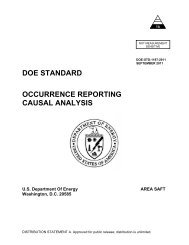
NE Standard<br />
NE C 15-3T<br />
October 1974<br />
Canceled July 1996<br />
CURRENT PULSE PREAMPLIFIERS FOR USE WITH FISSION<br />
COUNTERS<br />
INCLUDING AMENDMENTS 1 AND 2<br />
No Replacement
CURRENT PULSE<br />
FOR USE WITH<br />
Any further distribution by any holder of this docu-<br />
ment or of the data therein to third parties represent-<br />
ing <strong>for</strong>eign interests. <strong>for</strong>eign governments, <strong>for</strong>eign<br />
companies and <strong>for</strong>eign subsidiaries or <strong>for</strong>eign divisions<br />
of U. S. companies should be coordinated <strong>with</strong> the<br />
Director, Division of Reactor Development and Tech-<br />
nology, U. S. Atomic Energy Commission.<br />
Division of Reactor Development and Techn<br />
United States Atomic Energy Commission
\ /'<br />
,'<br />
//<br />
CAUTION ,' JUNE 1991<br />
This standard is<br />
It has not been maintained and m ent.<br />
Be<strong>for</strong>e this<br />
31<br />
\
RDT STANDARD RDT c 15-3~, Amendment 2<br />
UNITED STATES ATOMIC ENERGY COMMISSION<br />
DATE October 1974<br />
DIVISION OF REACTOR RESEARCH AND DEVELOPMENT PAGE 1 OF 1<br />
CURRENT PULSE PREAMPLIFIERS FOR USE WITH FISSION COUNTERS<br />
AMENDMENT 2<br />
This amendment <strong>for</strong>ms a part o<br />
dated August 197 1,<br />
Page 18, 4.5.8: Change the th to read:<br />
input can then be<br />
to the preamplifier<br />
= the preamplifier voltage gain (also equal to preamplifier<br />
current gain)<br />
B .W . = the noise bandwidth of the amplifier filter (one MHz <strong>for</strong><br />
CR-RC filter time constant of 0.5 psec)<br />
R = the resistor value connected to the input of the<br />
preamp1 if ier .<br />
(For filter time constants other than 0.5 pec , the B .W. can be calculated<br />
from the expression B .W. equals 1/(2~) where T is the filter time constant<br />
in seconds.) The noise current spectral density obtained shall be less<br />
than 15 pA per *. The noise current spectral density obtained <strong>for</strong> the -<br />
Type B preamplifier and either output of the Type C preamplifier shall<br />
be less than 30 pA per F.
R D T S T A N D A R D<br />
RDT C 15-3T Amendment 1<br />
UNITED STATES ATOMIC ENERGY COMMISSION<br />
DIVISION OF REACTOR DEVELOPMENT AND TECHNOLOGY<br />
Date<br />
Page<br />
June 1973<br />
1 of 2<br />
CURRENT PULSE PREAMPLIFIERS FOR USE WITH FISSION COUNTERS<br />
Page 1, Scope: Add the<br />
Two gain options <strong>for</strong><br />
Page 1, 1.1: Add the f<br />
Two gain options<br />
gain (high or lo<br />
Page 4, 3.<br />
This amendment <strong>for</strong>ms a part o<br />
Page 4, Table 1: Change to read:<br />
Table 1<br />
<strong>Pulse</strong> Polarity and <strong>Current</strong> Gain Requirements<br />
<strong>for</strong> Type A, B and C <strong>Preamplifiers</strong><br />
Input Terminal Output Terminal<br />
Type Polarity Polarity <strong>Current</strong> Gain(+ 10%)<br />
Input 1 Input 2 output 1 output 2 output 1 output 2<br />
A h'egative n'egative 500*<br />
B n'egative Eegative 250*<br />
B Positive Negative 250k
Input Terminal Output Terminal<br />
RDT C 15-3T<br />
Amendment 1 -<br />
Page 2<br />
Type Pclarity Polarity <strong>Current</strong> Gain (+ 10%)<br />
Input 1 Input 2 Output 1 Output 2 output 1 output 2<br />
C Negative Negative Positive 125* 125*<br />
C Positive Negative 125*<br />
* Values shown are <strong>for</strong> the "low gain" option. ption, double<br />
the values shown.<br />
5. Page 4, 3.2.2: Change first senten<br />
The pulse rise time (time from when measured<br />
<strong>with</strong> an input pulse of 1.0 nse time and less than 5% overshoot<br />
shall be less than 10.0 nsec.<br />
6. Page 6, 3.3.3: Change 0 ma" in next to last sentence:<br />
7. Page 8, 3.3.7: "3.5.10" in last sentence, 3rd paragraph<br />
8. Page 8, .Ill1 to "3.5.10" in last sentence.<br />
9. Page 16, paragraph, change first sentence to read:<br />
at any convenient pulse rate and a<br />
pulse width of 100 nsec, apply a 0.4 mV pulse to a low gain preamplifier<br />
input (0.2 mV <strong>for</strong> a high gain preamplifier).<br />
In the second paragraph, change first sentence to read:<br />
Increase the input signal to 0.8 mV <strong>for</strong> a low gain type B preamplifier<br />
(0.4 mv <strong>for</strong> a high gain preamplifier) and to 2.0 mV <strong>for</strong> a low gain type<br />
C preamplfier (1.0 mV <strong>for</strong> a high gain preamplifier).<br />
10. Page 17, 4.5.3: Change "5.0 nsec" to 10.0 nsec" in third sentence.<br />
11. Page 18, 4.5.9: In the first paragraph, third sentence, change to read:<br />
Adjust the pulse generator <strong>for</strong> a 100 nsec pulse width, approximately a<br />
10 kHz pulse rate and apply a 0.5 mvpulse to the input of a low gain -<br />
preamplifier (0.25 mV to a high gain preamplifier).<br />
12. Page 22, 4.5.13: In the first sentence after the <strong>for</strong>mula, change<br />
" (Borninally 400) " to 'I (Nominally 500 or 1000) " .<br />
13. Page 24, 6.2.a: Change to read:<br />
a) Preamplifier type and gain (high or low) . (Section 1.1 and 3.2.1) .
R D T S T A N D A R D<br />
UNITED STATES ATOMIC ENERGY COMMISSION<br />
DIVISION OF REACTOR DEVELOPMENT AND TECHNOLOGY<br />
- -<br />
CURRENT PULSE PREAMPLIFIERS FOR USE WITH FISSION COUNTERS<br />
SCOPE<br />
1.1 Classification<br />
1.2 Applicability<br />
1.3 Definitions<br />
APPLICABLE DOCUMENTS<br />
2.1 AEC-RDT Standards<br />
2.2 Military Standards<br />
2.3 Federal<br />
2.4<br />
3.1 Genera<br />
3.5 Mater<br />
TABLE OF CONTENTS<br />
3.7 General Assembly and Layout Design<br />
3.8 Reconunended Circuit Design <strong>for</strong> an Input Stage<br />
3.9 Identification<br />
3.10 Maintenance Manual<br />
4. QUALITY ASSURANCE REQUIREMENTS<br />
4.1 Quality Assurance Program<br />
4.2 Design Approval<br />
4.3 Material Certification<br />
4.4 Alternate Materials<br />
4.5 Tests<br />
4.6 Test Result Certification<br />
4.7 Test Instrument Certification<br />
5 . PREPARATION FOR DELIVERY<br />
6. NOTES AND ORDERING DATA<br />
6.1 Bid Proposal<br />
6.2 Ordering Data<br />
RDT C 15 - 3T<br />
Date August 1971<br />
Page
APPENDIX A<br />
APPENDIX B<br />
APPENDIX C<br />
RDT C 15-3T<br />
Page<br />
2 5<br />
2 7
R D T S T A N D A R D RDT C 15-3 T<br />
UNITED STATES ATOMIC ENERGY COMMISSION<br />
DIVISION OF REACTOR DEVELOPMENT AND TECHNOLOGY<br />
CURRENT PULSE PREAMPLIFIERS FOR USE WITH FISSION COUNTERS<br />
1. SCOPE<br />
Date August 1971<br />
Page 1 of<br />
This standard covers three types of ended input<br />
and output, differential input and single<br />
and output) <strong>for</strong> use <strong>with</strong> fission counters<br />
the current pulse of the counter. It per<strong>for</strong>mance and<br />
the tests to determine this<br />
overall construction guides are given to vity of operation and<br />
good shielding against<br />
Various connections of the £is ias potential to the differ-<br />
ent preamplifiers along <strong>with</strong> a sure the counter dc current are<br />
presented to acconawdate both guarded fission counters.<br />
A filter <strong>for</strong> the cou r b i w t i a l is an integral part of the pre-<br />
amplifier.<br />
The counter b&\he supplies <strong>for</strong> preamplifier power ire not<br />
a part of the prea<br />
and output cables are nominally 50 ohms <strong>for</strong> the<br />
100 ohms <strong>for</strong> the twin-conductor type. This<br />
other impedances.<br />
1.1 Classification. <strong>Preamplifiers</strong> will be one of the following types<br />
as specified in the Ordering Data.<br />
Type A (single-ended input and single-ended output) - This pre-<br />
amplifier obtains its signal from a single 50-ohm coaxial<br />
cable and develops an amplified output signal across an<br />
external 50-ohm load.<br />
Type B (differential input and signal-ended output) - This pre-<br />
amplifier obtains two signals of identical size and shape<br />
but of opposite polarity from two 50-ohm coaxial cables<br />
and develops an amplified output signal across an external<br />
50-ohm load. (In some ca'ses the input signal may be ob-<br />
tained from a 100-ohm twin-conductor cable. )<br />
Type C (differential input and differential output) - This pre-<br />
amplifier is similar to Type B except that it develops<br />
two amplified output signals of identical shape but<br />
opposite polarity across two separate 50-ohm loads. (In<br />
some cases it may be required that the output drive a<br />
100-ohm twin-conductor cable.)<br />
3 0
RDT C 15-3 T<br />
Page 2<br />
1.2 A~vlicability. These preamplifiers will be used to amplify narrow<br />
current pulses from fission counters to obtain high efficiency detection of<br />
neutrons in garmna fields in excess of 106 R/hr. The length of the input<br />
cable to the preamplifier is limited only by transmission losses and external<br />
noise pick-up.<br />
Type B and Type C preamplifiers, <strong>with</strong> more complex and expensive cabling,<br />
exploit the high common-mode rejection capabilities of<br />
it is required that both the cabling<br />
highly balanced condition. Twin-conductor<br />
and output<br />
common shield.<br />
frequency response than coaxial<br />
provised adaptations of coaxial hardware.<br />
The use of input cables <strong>with</strong> imp than 50 ohms is possible<br />
provided the input impedance of the p s modified accordingly.<br />
The noise density specified a cable impedance of 50 ohms<br />
increasing <strong>for</strong> values above 50.<br />
ohms. However, <strong>with</strong> impedances it is theoretically<br />
se ratio provided the time constant<br />
is small compared to<br />
cable losses are com-<br />
parable.<br />
will provide a lighter<br />
However, the 50-ohm<br />
impedance is more compatible <strong>with</strong> existing high frequency equipment such as<br />
amplifiers, discriminators and attenuators.<br />
These preamplifiers can be used <strong>with</strong> counters other than the fission type<br />
provided the 1000 volt rating of input coupling capacitor and filter network<br />
<strong>for</strong> counter bias supply is not exceeded. <strong>Use</strong> <strong>with</strong> counters having electron<br />
collection times greater than 200 nsec is not recomended. The signal-to-<br />
noise ratio is degraded and the input coupling time-constant (10 psec minimum)<br />
is not sufficient to reduce the undershoot to a tolerable level. (The limit-<br />
ations of the voltage rating of the input coupling capacitor and input coup-<br />
ling time constant can be eliminated <strong>with</strong> a guarded type counter since a direct<br />
current connection to the preamplifier is possible.)<br />
1.3 Definitions<br />
1.3.1 Supplier. The individual or company entering into a contract,<br />
subcontract, or purchase order issued by the purchaser.<br />
1.3.2 Purchaser. The agency responsible <strong>for</strong> issuance and adminis-<br />
tration of a contract, subcontract, or purchase order imposing this standard<br />
or portions thereof.
2 . APPLICABLE DOCUMENTS<br />
RDT C 15-3T<br />
Page 3<br />
The following documents are a part of this standard to the extent indicated<br />
where they are cited in the text. The issue of a document in effect on the date<br />
of the order, including any amendments also in effect on that date, shall apply<br />
unless otherwise specified. Where the standard appears to conflict <strong>with</strong> the<br />
requirements of a reference document, the supplier shall call it to the attention<br />
of the purchaser <strong>for</strong> resolution.<br />
2 -1 AEC-RDT Standards<br />
RDT F 2-2T, Quality Assurance<br />
2.2 Military Specifications<br />
Mil-R-55182D, Resistors, Fixed, General<br />
Mil-C-39014B, Capacitors, Dielectric (General Purpose) ,<br />
Mil-C-11015D, Capacit ramic Dielectric (General Purpos'e) ,<br />
Mil-C-25D,<br />
Mil-P-13949C, Plastic Sheet, Laminated, Copper Clad, (For Printed Wiring)<br />
Mil-W- 16878D (Navy) , Wire, Electrical, Insulated, High Temperature<br />
Mil-C-39012B, Connectors, Coaxial, Radio Frequency, General Spec if ications<br />
For<br />
Mil-C-26482E, Connectors, Electric, Circular , Miniature, Quick Disconnect,<br />
Environment Resisting<br />
2.3 Federal Specifications<br />
QQ-P-416b, Plating, Cadmium (Electrodeposited)<br />
QQ-S-571d, Solder; Tin Alloy; Lead-Tin Alloy; and Lead Alloy<br />
2.4 American Society <strong>for</strong> Testing and Materials Specifications<br />
ASTM A620, Carbon Steel Sheet, Cold-Rolled, Drawing Quality, Special<br />
Killed.
3. TECHNICAL REQUIREMENTS<br />
RDT C 15-3 T<br />
Page 4<br />
3.1 General. The preamplifier shall be an electronic device construc-<br />
ted of silicon transistors and high quality circuit components and assembled<br />
in a double-walled metal enclosure of high conductance to shield it from<br />
external electrical fields and ground currents.<br />
and its input e of the<br />
cable. The input signal to the<br />
across the cable by the current pulse of the fissi<br />
this voltage<br />
degradation caused from<br />
ance time constant and<br />
3.2 Per<strong>for</strong>mance<br />
3.2.1 <strong>Pulse</strong> <strong>Current</strong> Gain.<br />
a rectangular pulse de and any convenient pulse rate<br />
shall be according to Table 1. f output current shall be indi-<br />
cated by the voltage<br />
put terminal and sure of the input current shall be<br />
deduced from the nput terminal and the assumption that<br />
the input<br />
v TABLE 1<br />
<strong>Pulse</strong> Polarity and <strong>Current</strong> Gain Requirements <strong>for</strong> Type A, B, and C <strong>Preamplifiers</strong><br />
Type Input Terminal Output Terminal<br />
and<br />
Polarity Polarity <strong>Current</strong> Gain (go%)<br />
No. 1 No. 2 No. 1 No. 2 No. 1 No. 2<br />
A Negative Negative 400<br />
B Negative Negative 200<br />
B Positive Negative 200<br />
C Negative Negative Positive 100 100<br />
C Positive Negative Positive 100 100<br />
3.2.2 <strong>Pulse</strong> Rise Time. The pulse rise time (time from 10% to 90%<br />
of final amplitude) when measured <strong>with</strong> an input pulse of 1.0 nsec +lo% rise<br />
time and less than 5% overshoot shall be less than 5.0 nsec. The output<br />
pulse shall be measured across a 50-ohm resistor connected between the output<br />
terminal and signal ground. The overshoot shall not exceed 10%. The measurement<br />
shall be made on an output signal of 200 mV ~25% <strong>with</strong> polarities as given<br />
in Table 1.
RDT C15-3T<br />
Page 5<br />
3.2.3 Integral Nonlinearity. The preamplifier shall be capable of<br />
driving a 50-ohm resistor connected between the output terminal and signal<br />
ground to 400 mV <strong>with</strong> less than 1.09. integral nonlinearity. The pulse polar-<br />
ity shall be as given in Table 1.<br />
3.2.4 Output Saturation Level. The preamplifier saturation level<br />
shall be a minimum of 600 mV when driving a 50-ohm resistor connected be-<br />
tween the output terminal and signal ground. The shall be<br />
as given in Table 1.<br />
3.2.5 Output <strong>Pulse</strong><br />
shall be measured <strong>with</strong> a<br />
-<br />
+5% and at a pulse rate<br />
pulse as observed across<br />
pulse.<br />
lifier shall be such<br />
up to 10 MHz. The measurement s<br />
having a width of 50 nsec<br />
+lo% output pulse across a<br />
-<br />
output terminal) when referred to either input shall be less than 30 pA rms<br />
per ,/HZ.<br />
3.2.8 Gain Stability. The gain change <strong>with</strong> temperature when measured<br />
between 25OC to 66%. shall be less than 0.05%/OC <strong>with</strong> the gain at 25OC as a<br />
reference.<br />
3.2.9 Input Impedance. The input impedance shall be such that the<br />
reflections from the input as observed at the pulse generator terminals shall<br />
be less than +lo% of the applied input signal. The test pulse wave<strong>for</strong>m shall<br />
have a rise time of 1.0 nsec 50% <strong>with</strong> less than 5% overshoot and shall be<br />
applied to the preamplifier input <strong>with</strong> a coaxial cable having a characteristic<br />
impedance of 50 ohms.<br />
3.2.10 Noise Imnunitv. The shielding shall be such that a current<br />
pulse of 100 rnA through the outside enclosure of the preamplifier shall not<br />
result in an output pulse above the noise level when measured <strong>with</strong> a O.lO-psec<br />
CR-RC filter. The current test pulse shall be 100 nsec wide +10% and have a<br />
rise time of 1.0 nsec +10% and less than 5% overshoot.<br />
3.2.11 Input Protection. The input shall be capable of discharging<br />
a 0.01 pF capacitor which is charged to either positive or negative 1000 volts<br />
<strong>with</strong>out damage to the preamplifier.
RDT C 15-3 T<br />
Page 6<br />
3.2.12 Common-Mode Rejection. The commonmode rejection <strong>for</strong> the<br />
Type B and Type C preamplifiers shall be in excess of 40 dB from 50 kHz to<br />
20 MHz.<br />
3.2.13 Environmental Conditions. The per<strong>for</strong>mance of the preampli-<br />
fier as specified in Sections 3.2.1 and 3.2.2 shall be retained <strong>for</strong> the fol-<br />
lowing conditions :<br />
3.3 Electrical<br />
(50.05 V), +12 V (20.<br />
1. After 24 hours of operation at 40' a relative<br />
humidity of 90 to 95%.<br />
humidty .<br />
coupling time constant<br />
age rating of the input coupling<br />
counter bias potential) and shall be as<br />
0.005 V peak to peak on each supply. The current from each supply shall not<br />
exceed 100 mA. Thes'e voltages shall be obtained from power supplies external<br />
to the preamplifier and the regulation applies to the voltage at the terminals<br />
of the power supplies.<br />
3.3.4 <strong>Fission</strong> Counter Bias Filter Network. The preamplifier shall<br />
contain a filter network <strong>for</strong> the fission counter bias potential <strong>with</strong> a minimum<br />
voltage rating of 1000 volts dc. It shall consist of a minimum of three equal<br />
RC (low pass) sections <strong>with</strong> a total series resistance of not less than 15 x 103<br />
ohms. The capacitor values shall not be less than 0.01 pF and shall be as speci-<br />
fied in Section 3.5.4. All resistors shall be as specified in Section 3.5.1.<br />
3.3.5 Bias Supply and <strong>Fission</strong> Counter Connection. The bias supply and<br />
fission counter connection shall be one of the following types as specified in<br />
the Ordering Data. Refer to Fig. 1 <strong>for</strong> description of the various types.<br />
Type AUG - Type A preamplifier <strong>with</strong> unguarded counter<br />
Type AG - Type A re amplifier <strong>with</strong> guarded counter<br />
Type BUG or Type CUG - Type B or Type C preamplifier <strong>with</strong> unguarded<br />
counter<br />
Type BG or Type CG - Type B or Type C preamplifier <strong>with</strong> guarded counter.
RDT C 15-3 T<br />
Page 8<br />
3.3.6 Test Point <strong>for</strong> Bias Voltage. A test point shall be available<br />
to monitor the bias voltage. The test voltage shall be obtained from a volt-<br />
age divider network as shown in Fig. 1. All resistors in this network shall<br />
be as specified in Section 3.5.2. The connector <strong>for</strong> this test point shall be<br />
as specified in Section 3.5.10.<br />
3.3.7 Test Points <strong>for</strong> <strong>Fission</strong> Counter DC <strong>Current</strong>. Test points shall<br />
be available to monitor the fission chamber dc current<br />
<strong>with</strong> the normal operation of the counter.<br />
For the unguarded counter, the test points of two jacks<br />
(<strong>with</strong> voltage ratings in excess of 1000 volts dc<br />
output of the bias filter network along <strong>with</strong> a or a convenient<br />
ground point as shown in Figs. 1A and 1C.<br />
R<br />
For the guarded counter, the consist of a coaxial<br />
connector connected to a diode clamp 1B and ID. This<br />
conn'ector shall be as specified in S<br />
.<br />
available to apply a test signal<br />
such inputs shall be<br />
required <strong>for</strong> the impedance of this input<br />
ac coupled, the time<br />
a source impedance<br />
of 50 ohms.) This capable of <strong>with</strong>standing voltages of 250 volts.<br />
3.3.9 Input ~ihA Connector. A coaxial connector as specified in<br />
Section 3.5.11 shall be supplied <strong>for</strong> the input signal.<br />
preamplifier shall require two such connectors.<br />
The Type B and Type C<br />
3.3.10 Output Signal Connector. A coaxial connector as specified in<br />
Section 3.5.10 shall be supplied <strong>for</strong> the output signal. The Type C preamplifier<br />
shall require two such connectors.<br />
3.3.11 Power Supply Connector. A connector shall be provided to apply<br />
power to the preamplifier. A type as described in Section 3.5.12 is recommended.<br />
This connector shall be as specified in the Ordering Data.<br />
3.3.12 Counter Bias Connector. A connector as specified in Section<br />
3.5.11 shall be supplied to apply a counter bias potential.<br />
3.3.13 Termination Resistor For Counter Bias Cable. This resistor is,<br />
shown in Fig. 1B as resistor R and shall be as specified in the Ordering Data.<br />
3.4 Enclosure. The enclosure <strong>for</strong> the preamplifier shall be double-<br />
walled box <strong>with</strong> inner and outer boxes electrically insulated. (See Fig. 2 <strong>for</strong><br />
illustration.)
BU1LD;NC<br />
GROUND A<br />
REMOVABLE COVERS<br />
?. 3<br />
it--- l<br />
1<br />
ID3 NOT S'iOWNl<br />
FIGURE 2<br />
REMOVABLE :OVERS<br />
ENCLOSURE AND GENERA1<br />
RDT C 15-3T<br />
Page 9<br />
INSULATOR<br />
INPUT CONNECTOR<br />
@ our~ur COKNE~TOR<br />
@ POWER CONNECTOR<br />
@ COUhTER BIAS CONNECTOR<br />
@BIAS FILTER CGKFLPTMENT<br />
@COL\TEQ aiis CO~IYECTOR<br />
0 IhPCIT TLST COhNECTOR
RDT C 15-3 T<br />
Page 10<br />
3.4.1 Hole <strong>for</strong> Invut Signal Cable in Outer Box. A hole Dl shall be<br />
located on the outer box to permit the mounting of a. fitting <strong>for</strong> an integral<br />
connection to the external shield of the input cable. (This shield may be<br />
the outer shield of a triaxial cable, the outer shield of a multiple shielded<br />
cable, or the outer surface of a solid shield.) This hole shall be specified<br />
in the Ordering Data as,<br />
I$&%<br />
Dl - (Number Required) - (Inches Dia<br />
3.4.2 Hole <strong>for</strong> Input Signal Cable in Inner D2 shall be<br />
located on the inner box to permit the optional nput connector<br />
(other than that specified in Section fo an.integra1<br />
connection to the rying shield may be<br />
a multiple shielded<br />
shall be specified<br />
in the Ordering Data as,<br />
es Diameter)<br />
3.4.3 Hole <strong>for</strong> Output&alB,VJin Inner Box. A hole D3 shall be<br />
located on the inner b ng of an output signal connector other<br />
than that specified in<br />
Ordering Data as,<br />
This hole shall be specified in the<br />
3.4.4 KW equired) - (Inches Diameter)<br />
Hole fhbwer, Output Signal, and Counter Bias Cables in<br />
Outer BOW A hole D4 shall be located on the outer box to<br />
permit the mounting of a fitting <strong>for</strong> an integral connection to the external<br />
shield of the cable group consisting of the output signal, power and counter<br />
bias cables. This hole shall be specified in the Ordering Data as,<br />
D4 - (Inches Diameter)<br />
3.4.5 Covers <strong>for</strong> the Inner and Outer Boxes. The top and bottom sides<br />
of the inner and outer boxes shall have removable covers to permit access to<br />
both sides of the printed circuit boards.<br />
3.4.6 Physical Dimensions of Inner Enclosure. The height of the<br />
inner enclosure shall not exceed 2-112 inches and the total volume shall not<br />
exceed 120 cubic inches.<br />
3.4.7 Physical Dimensions of Outer Enclosure. The outer enclosure .<br />
shall have a size which will permit easy connection and disconnection of<br />
cables to the preamplifier.<br />
3.5 Materials<br />
3.5.1 Resistors. All resistors except as noted in Section 3.5.2 shall<br />
be of the film, (high stability) type as specified in Mil-R-55182D. All resis-<br />
tors shall con<strong>for</strong>m to the 21.0% resistance tolerance and the 2100 parts/milli~n/~C<br />
temperature characteristic and have solderable terminals. The outer impregnation<br />
shall be of the con<strong>for</strong>mal type <strong>with</strong> one or two coats of high temperature epoxy
RDT C 15-3 T<br />
Page 11<br />
enamel. The failure rate level shall not exceed 1.0%/1000 hour of operation.<br />
3.5.2 Resistors (<strong>for</strong> Counter Bias Test)'. These resistors will have<br />
a minimum of a 114 watt rating <strong>for</strong> an ambient temperature of 60°C. They will<br />
have a tolerance of 21.0% and a 2200 parts/million/"C temperature characteristic<br />
and solderable terminals. The voltage rating will not be less than 1000 volts<br />
dc <strong>with</strong> a voltage coefficient not to exceed 25 parts/million/volt.<br />
h<br />
3.5.3 Capacitors (~e~amic). A l l ceramic c@ ors except as noted<br />
in Section 3.5.4 shall be of a type as specified 014B. The capacitor<br />
tolerance shall be 210%. The rated temperatu ration shall be -15<br />
to +85'C. The maximum change in capacitance fer ce) over this range<br />
shall be <strong>with</strong>in 95% <strong>with</strong> no voltage appli n +15% and -25% <strong>with</strong><br />
maximum rated voltage applied.<br />
1000 hours of operation.<br />
The fa shall not exceed 1.0%/<br />
3.5.4 Capacitors (<strong>for</strong> m o n c&n\er bias filterl. The capacitors<br />
<strong>for</strong> the fission counter bias fi~t(e~shall%dof a type as specified in Mi1-C-<br />
11015D. The capacitor shall rance of 220% and a voltage rating of<br />
1000 volts dc. The rated nge of operation shall be -55.to +85OC.<br />
The maximum change in capa reference) over this range shall be<br />
<strong>with</strong>in +30% and -70%<br />
maximum rated volt<br />
e applied and <strong>with</strong>in +30% and -%OX <strong>with</strong><br />
input coupling). The capacitor <strong>for</strong> the input<br />
s specified in Mil-C-25D <strong>with</strong> axial wire leads.<br />
lerance of ~10% and a voltage rating of 1000 volts<br />
nge of operation shall be 3 5 to +85'C. The<br />
maximum change in capacitance (25'C reference) over the rated temperature<br />
range and <strong>with</strong> maximum rated voltage applied shall oe <strong>with</strong>in +7.5% and -10%.<br />
3.5.6 Capacitors (electrolytic). All electrolytic capacitors shall<br />
be tantalum <strong>with</strong> the solid electrolyte as specified in Mil-C-39003A. The<br />
capacitor tolerance shall be 220%. The failure rate level shall not exceed<br />
1.0%/1000 hours of operation.<br />
3.5.7 Transistors. All transistors shall be of the silicon planar<br />
expitaxial type.<br />
3.5.8 Diodes (conventional). All conventional diodes shall be of<br />
the silicon type.<br />
3.5.9 Printed Circuit Board. The printed circuit board shall he of<br />
the plastic sheet, laminated, copper clad type as specified in ~il-P-13949~,<br />
using Type GH base material <strong>with</strong> cladding on both sides. The copper-foil<br />
thickness of each side shall be 2 ounces per square foot (0.0028 inch nominal<br />
thickness). The nominal overall thickness of the sheet shall be 1/16 (0.062)<br />
inch.<br />
3.5.10 Coaxial Connector (Type TNC). This connector shall be as<br />
specified in Mil-C-35012B <strong>with</strong> a tarnish-free, silver-plated, brass shell.
RDT C 15-3T<br />
Page 12<br />
3.5.11 Coaxial connector (Type N). This connector shall be as<br />
specified in Mil-C-35012B <strong>with</strong> a tarnish-free, silver-plated, brass shell.<br />
3.5.12 Connector (power supply). This connector shall be a miniature,<br />
circular type con<strong>for</strong>ming to Mil-C-26482E <strong>with</strong> gold-plated contacts and a shell<br />
made of a ferrous alloy material.<br />
3.5.13 Hook-Up Wire. The to Mil-W-16878D<br />
(Navy). The conductor shall be made up of round cross- individually<br />
silver-plated, soft-annealed copper wires. The<br />
temperature rating and a voltage rating of 600 volt<br />
3.5.14 Solder. All solder<br />
QQ-S-571d <strong>with</strong> an alloy of 60% tin,<br />
Type R, rosin. No other soldering fluxes<br />
be made of 20 gauge<br />
(0.0359 inch), carbon steel sheet, c quality, special killed<br />
as specified in ASTM A 620-68.<br />
3.6 Construction. The obtain approval of the fabrication<br />
tion (see Section 4.2).<br />
recessed contacts.<br />
Each transistor shall be mounted in a<br />
closed entry and<br />
3.6.2 integrahdbircuit Mounting. Each integrated circuit shall be<br />
mounted in a Teflon insugted socket <strong>with</strong> gold-plated, beryllium copper, re-<br />
cessed contacts.<br />
3.6.3 Printed Circuit Board Plating. The printed circuit board shall<br />
be gold-plated <strong>with</strong> a plating thickness of 0.0002 inch minimum and 0.0003 inch<br />
maximum. The gold shall be 23 carat hard plate and 99.5% pure.<br />
3.6.4 Enclosure Plating. After all drilling, bending, and welding or<br />
silver soldering, the enclosure shall be plated <strong>with</strong> 0.0005 inch thick cadmium<br />
as per Federal Specification QQ-416b <strong>with</strong> Type I plating. The final finish<br />
shall be a post-plating bright dip followed by a lacquer dip.<br />
3.6.5 Input Cable Terminating Resistor. This resistor or resistors<br />
shall be located to permit easy removal and installation,<br />
3.6.6 Input Cable Connection. A gold-plated, split-lug terminal shall<br />
be available to make a connection to the input cable center conductor.<br />
3.6.7 Removable Covers <strong>for</strong> the Enclosure. Removable covers shall not<br />
create long slits or cracks. Covers shall either be the overlapping type <strong>with</strong><br />
anti-rattle clips or a flat plate fastened down <strong>with</strong> screws at a maximum<br />
spacing of 2.0 inches.<br />
3.7 General Assembly and Layout Design. The general assembly and layout<br />
shall have the following features. (See Fig. 2 <strong>for</strong> illustration.)
1. The input connectors shall be mounted on the inner box.<br />
2. Connectors <strong>for</strong> the output signal, preamplifier power and<br />
counter bias potential shall be mounted on the inner box.<br />
3. The ground planes of all printed circuit boards shall be<br />
firmly soldered to the walls of the inner box.<br />
4. Each amplifier section (three shown in Fig. 2) and the counter<br />
bias filter shall be partitioned off<br />
soldered to the ground plane and<br />
of the inner box.<br />
5. Each amplifier section shall be s<br />
filters on the power lead.<br />
6. Each amplifier section shall b<br />
return lead.<br />
3.9 Identification.<br />
OUT SIG (<strong>for</strong> output signal)<br />
PWR (<strong>for</strong> preamplifier power)<br />
HV OUT (<strong>for</strong> bias connection to counter)<br />
HV IN (<strong>for</strong> counter bias supply input)<br />
HV TEST (<strong>for</strong> counter bias test)<br />
DC OUT (<strong>for</strong> dc current output)<br />
IN TEST (<strong>for</strong> test input)<br />
DC (+) (<strong>for</strong> high side dc current test point)<br />
DC (-) (<strong>for</strong> low side dc current test point)<br />
GND (<strong>for</strong> ground test point)<br />
a separate power<br />
er stamped or printed <strong>with</strong> oil, grease<br />
identified on the printed circuit board <strong>with</strong><br />
3.10 Maintenance Manual. The supplier shall supply three copies of a<br />
maintenance manual <strong>for</strong> each preamplifier type purchased. This manual shall<br />
include :<br />
1. Complete drawing of the circuit,<br />
2. Complete drawing of all metal work,<br />
3. Complete drawing of the printed circuit board layout,<br />
4. Voltage and wave<strong>for</strong>m chart <strong>for</strong> the circuit. (This may be part<br />
of Item I.),<br />
5. Details <strong>for</strong> all tests and adjustments,<br />
6. Complete parts list.
4. QUALITY ASSURANCE REQUIREMENTS<br />
RDT C 15-3 T<br />
Page 14<br />
4.1 Quality Assurance Program. The supplier's quality assurance prog-<br />
ram shall con<strong>for</strong>m to Sections 1, 2, 3, 4, 5, and 8 of RDT F2-2.<br />
4.1.1 Program Plan. A quality assurance program plan shall be pre-<br />
pared by the supplier and submitted to the<br />
specified in Section 6.1. The requirements<br />
dance <strong>with</strong> Section 2.2 of RDT F2-2.<br />
4.2 Design Approval. The supplier<br />
purchaser the following designs <strong>for</strong> approval,<br />
1. Preliminary design of<br />
bid proposal as specified<br />
2. Fabrication design of<br />
cation shall not be st<br />
design has been extend<br />
unapp d resubmitted <strong>for</strong> approval.<br />
material substitution.<br />
ot covered by this standard, the certifi-<br />
approval by the purchaser.<br />
The supplier may recommend alternate materials<br />
e considers a substitute material will produce an<br />
4.5 Tests. The following tests shall be per<strong>for</strong>med by the supplier unless<br />
otherwise specified in the Ordering Data. Each preamplifier shall pass the<br />
specified tests <strong>for</strong> acceptance. If the preamplifier has been constructed <strong>for</strong><br />
an integral connection to the input cable, a connector of the type specified<br />
in Section 3.5.10 shall be temporarily mounted to per<strong>for</strong>m all tests requiring<br />
connections to the preamplifier input.<br />
4.5.1 Test Equipment. The supplier shall utilize test equipment<br />
sufficient to determine con<strong>for</strong>mance of the preamplifier to applicable require-<br />
ments. The test instruments shall be adjusted and calibrated against standards<br />
having known valid relationship to nationally recognized standards, when such<br />
exist. If no national standards exist, the supplier shall document the basis<br />
<strong>for</strong> his calibration. Refer to Section 5.8 of F2-2. Suggested test instruments<br />
are listed.<br />
4.5.1,l Oscillosco~e (sampling). <strong>Use</strong>d to measure gain, rise time,<br />
and input impedance. (Tektronix 661 Sampling Oscilloscope or equal).<br />
1. Vertical sensitivity - 10 mV/cm<br />
2. Horizontal deflection - 5 nsec/cm<br />
3. Rise time - less than 0.35 nsec<br />
4. Input impedance - 50 ohms and high impedance probe (XI0 at<br />
3.5 pF in parallel <strong>with</strong> 10 megohms) .
RDT C15-3 T<br />
Page 15<br />
4.5 .l. 2 Oscilloscope. <strong>Use</strong>d to measure gain stability, integral<br />
nonlinearity, output saturation level, and common-mode rejection. (Tektronix<br />
541A <strong>with</strong> Type L plug-in or equal.)<br />
1. Vertical sensitivity - 5 mV/cm<br />
2. Horizontal deflection - 20 nsec/cm<br />
3. Rise time - less than 10 nsec.<br />
easure gain, rise<br />
ode1 215A or<br />
3. Output - positive<br />
load<br />
4. Output impedance<br />
7. <strong>Pulse</strong> r<br />
attenuator <strong>with</strong> 12 calibrated dB steps.<br />
from 10 nsec to 100 nsec<br />
le from 1.0 kHz to 1.0 MHz.<br />
4. Output - positive or negative 1.0 volt into 50-ohm external load<br />
5. Output impedance - 50 ohms.<br />
4.5.1.5 <strong>Pulse</strong> Generator (tail pulse). <strong>Use</strong>d to measure noise,<br />
integral nonlinearity and output saturation level. (Tennelec TC800 or equal.)<br />
1. Rise time - less than 20 nsec<br />
2. Fall time - greater than 100 psec, RC tail<br />
3. <strong>Pulse</strong> rate - 60 Hz.<br />
4.5.1.6 <strong>Pulse</strong> Amplifier (CR-RC filtered). <strong>Use</strong>d to measure noise<br />
and noise immunity (ORTEC Model 410 or equal).<br />
1. CR-RC filter - 0.10 psec and 0.5 psec 223% time constant<br />
2. Gain - adjustable from 10 to 1000<br />
3. Rise time (<strong>with</strong> no filter) - less than 60 nsec.
RDT C 15-3 T<br />
Page 16<br />
4.5.1.7 AC Voltmeter (true RMS). <strong>Use</strong>d to measure noise.<br />
(Ballentine Model 321 or equal.)<br />
1. Range - 1.0 mV to 30 volts<br />
2. Bandwidth - 5 Hz to 4 MHz <strong>with</strong> ~ 4 % accuracy.<br />
4.5.1.8 Temperature Test Chamber. <strong>Use</strong>d to gain stability<br />
(Delta Design, Inc. Model 6545A oi equal.)<br />
1. Range - 25°C to 70°C<br />
2. Accuracy - 22°C.<br />
4.5.1.9 <strong>Pulse</strong> Discriminator (intgg<br />
stability. (ORTEC Model 406 or equal.)<br />
rejection.<br />
protection.<br />
1. Threshold level- adj<br />
turn precision poten<br />
1. Output -)dsitive or negative 1000 volts.<br />
<strong>Use</strong>d to measure common-mode<br />
to 1.0 volt rms across a 50-ohm load.<br />
. <strong>Use</strong>d to measure input<br />
4.5.1.12 Power Supply, Low Voltage (two required). <strong>Use</strong>d in all<br />
tests to power preamplifier.<br />
1. Output - positive or negative and adjustable from 12 volts<br />
to 24 volts.<br />
4.5.1.13 Attenuator. 20 dB. 50 ohm (four required). <strong>Use</strong>d as<br />
required. (Tektronix 011-059 or equal.)<br />
1. Rise time - less than 0.5 nsec <strong>with</strong> less than 5% overshoot.<br />
2. Power rating - 1/2 watt<br />
4.5.1.14 Termination. 50 ohm (four requiredl. <strong>Use</strong>d as required.<br />
(Tektronix 011-049 or equal .)<br />
4.5.2 <strong>Pulse</strong> <strong>Current</strong> Gain Test. Using the rectangular pulse gener-<br />
ator at any convenient pulse rate and a pulse width of 100 nsec, apply a 0.5<br />
mV pulse to the preamplifier input. For the 215A pulse generator, this will<br />
require the 6 dB position of its attenuator switch and four external 20 dB<br />
attenuators. <strong>Use</strong> RG 58/U to make the connection to the preamplifier input.<br />
Connect the output of the preamplifier to the input terminal of the oscillo-<br />
scope using RG 58/U cable and a 50-ohm termination at the oscilloscope. The<br />
amplitude of the pulse observed out of the Type A preamplifier shall be 200 mV
RDT C 15-3T<br />
Page 17<br />
- +lo%. The current gain and polarities of input and output pulses are given<br />
in Table 1.<br />
Increase the input signal to 1.0 mV <strong>for</strong> the Type B preamplifier and<br />
to 2.5 mV <strong>for</strong> the Type C preamplifier. The output of the Type B preamplifier<br />
shall be 200 mV 50%. Each of the two outputs of the Type C preamplifier<br />
shall be 250 mV 210% but of opposite polarity. The complete tests of the<br />
Type B and Type C preamplifiers shall require gain measurements from each<br />
input. <strong>Current</strong> gains and pulse polarities are also<br />
3.2.13.<br />
Repeat this test <strong>for</strong> the environmental c en in Section<br />
4.5.3 <strong>Pulse</strong> ~ise'~ime Test. etup of 4.5.2. Adjust<br />
and fall time of the output pulse. en the 10% and 90% points<br />
rshoot on either edge<br />
3.2.13.<br />
ental conditions given in Section<br />
amplifier input.) Connect<br />
the output of t o the input terminal of the oscilloscope using<br />
RG 58/U cable a nation at the oscilloscope.<br />
e generator to give an output of 200 mV <strong>with</strong> the pulse<br />
height potentiometer dial reading of 500 divisions (1000 divisions represent-<br />
ing the full ten turns of this potentiometer). The undershoot following the<br />
main pulse shall be ignored. The polarity of the main pulse shall be as given<br />
in Table 1. Increase the input signal a precise factor of two by adjusting<br />
the pulse height potentiometer to 1000 divisions. The output pulse shall in-<br />
crease by a factor of two +lye based on a 400 mV reference. This measurement<br />
requires a careful reading of the oscilloscope and using as much vertical de-<br />
flection as is possible. (A more precise reading can be obtained by replacing<br />
the oscilloscope <strong>with</strong> an amplifier and discriminator as per Sections 4.5.1.6<br />
and 4.5.1.9 and using the oscilloscope to monitor the output of the discrim-<br />
inator to ascertain the trigger levels.)<br />
For a Type B preamplifier, two readings shall be required, one <strong>for</strong><br />
each input. For a Type C preamplifier, four readings shall be required, two<br />
readings <strong>for</strong> each of two input signals.<br />
4.5.5 Output Saturation Level. Repeat the test setup of Section<br />
4.5.4. Adjust the pulse generator until there is strong evidence of satura-<br />
tion in the preamplifier output signal. This output level shall not be less<br />
than 600 mV.
Page 18<br />
4.5.1 Output <strong>Pulse</strong> Undershoot. Repeat the test setup of Section<br />
4.5.2 but at pulse rate not to exceed 10 kHz. Adjust the input pulse arrtpli-<br />
tude until a 400 mV 210% is obtained. Using as much vertical gain on the<br />
oscilloscope as possible, measure the undershoot following the main pulse.<br />
This undershoot shall be less than 1% of the main pulse. All main pulse<br />
polarities shall be as given in Table 1.<br />
4.5.7 <strong>Pulse</strong> Rate Response. Repeat the<br />
using the rectangular pulse generator <strong>with</strong> the<br />
Adjust the pulse width to 50 nsec and the pulse<br />
ators if needed) to give a 400 mV +lo% output pulse<br />
from 10 kHz to 10<br />
the output pulse.<br />
4.5.8 Noise Test. Connect a 50-0%<br />
preamplifier (both inputs <strong>for</strong> Type B and T<br />
preamplifier to the input of the puls sing RG 58/U cable and a<br />
50-ohm termination at the amplifier i the shaping time constants<br />
of amplifier (CR-RC filter) to give a<br />
time constant and an<br />
voltmeter to the<br />
(2 feet or less).<br />
reading on the voltmeter.<br />
Measure the he amplifier using the tail-type pulse<br />
generator <strong>with</strong> at lea<br />
c RC tail. The sinusoidal gain (AS) is 1.36<br />
times the pulse gain. e sinusoidal gain may also be obtained <strong>with</strong> the sinewave<br />
oscillator (Section .1.11) and the ac voltmeter by a measurement at<br />
the center frequency of the CR-RC filter.<br />
The noise current spectral density referred to the input can then be<br />
obtained by<br />
(AS) (RS) ~(B-w.)<br />
where Eo is the ac voltmeter output (100 mV in this case) and ApA is the pre-<br />
amplifier voltage gain (also equal to preamplifier current gain), B. W. is<br />
the noise bandwidth of the amplifier filter (one MHz <strong>for</strong> CR-RC filter time<br />
constant of 0.5 psec) and RS is the resistor value connected to the input.<br />
(For filter time constants other than 0.5 psec, the B.W. can be calculated<br />
from the expression B.W. = 1/27 where 7 is the filter time constant in<br />
seconds.) The value obtained shall be less than 15 pA per Bz. The value<br />
obtained <strong>for</strong> the Type B preamplifier and either output of e Type C preamp-<br />
lifier shall be less than 30 pA per .<br />
I,' Hz<br />
4.5.9 Gain Stability Test. Place the preamplifier in the temperature<br />
test chamber and apply suitable power supply voltages. Connect the pulse<br />
generator to the input <strong>with</strong> RG 58/U cable. Adjust the pulse generator <strong>for</strong><br />
a LOO nsec pulse width, approximately a 10 kHz pulse rate and apply a 0.5 mV<br />
pulse to the input. Connect the output to a pulse amplifier <strong>with</strong> 0.1 psec<br />
CR-RC filtering. <strong>Use</strong> a 50-ohm termination at amplifier input.
RDT C 15-3 T<br />
Page 19<br />
Connect the output of the amplifier to the discriminator input <strong>with</strong> a short<br />
length of RG 58/U cable.<br />
Adjust the temperature control of the environmental chamber <strong>for</strong> 25°C<br />
- +2OC and when stable adjust the gain of the amplifier until approximately a<br />
5.0 volt pulse is obtained at its output. Adjust the discriminator level<br />
scriminator.<br />
nnected to the<br />
ot spec if ied in<br />
he half-trigger<br />
point.) For a Type B preamplifier, two readi uired, one <strong>for</strong><br />
each input. For a Type C preamplifier, fo e required, two<br />
readings <strong>for</strong> each of two input signals.<br />
Raise the temperature to 60' abilize. Note<br />
sing the dis-<br />
, criminator readings at 25OC as alculate the percentage change<br />
per OC. It shall be less than<br />
o 25OC and allow the temperature to<br />
stabilize. Adjust shold to obtain the half triggering<br />
point. If this rea e than 20 mV(2.0 division of the discrimi-<br />
nator dial) from th , the test should be repeated.<br />
. Using the pulse generator at any con-<br />
venient pulse r of 15 nsec, apply a negative 25 mV pulse<br />
at the input to t escribed below. For the 215A pulse gen-<br />
erator this wi ts attenuator switch and two, 20 dB fixed<br />
attenuators. Mount both attenuators at the pulse generator and place a tee<br />
connector on the output of the second attenuator. <strong>Use</strong> at least a 20-foot<br />
section of RG 58/U cable to connect one port of the tee connector to the input<br />
preamplifier. Connect a high impedance oscilloscope probe (XI0 attenuation)<br />
to the other port of the tee connector. Any reflection from the preamplifier<br />
can be observed trailing the main pulse approximately 20 to 30 nsec. These<br />
reflections shall be less than +10% of the main pulse.<br />
To obtain more signal <strong>for</strong> the oscilloscope, a resistive network as<br />
shown in Fig. 3 can be used at the output of the second 20 dB attenuator.<br />
A 50-ohm termination shall be substituted <strong>for</strong> the preamplifier input<br />
impedance to confirm that there is no significant mismatch in the test set-<br />
up*<br />
4.5.11 Noise Immunity Test. Clamp the test fixture shown in Fig. 4<br />
to the preamplifier housing. Connect the pulse generator to the fixture <strong>with</strong><br />
a RG 58/U cable. Apply a 100-nsec wide pulse, 5.0 volts in amplitude to the<br />
test fixture. <strong>Use</strong> any convenient pulse rate. Connect the output of the pre-<br />
amplifier to the input of a pulse amplifier which has a 50-ohm impedance and<br />
a CR-RC filter <strong>with</strong> a 0.1 psec time constant. No output pulse from the main<br />
amplifier should be observed above the normal level of output noise.
INC OR BN<br />
TO PULSE GENERATOR<br />
(THROUGH TWO, 50-OHM,<br />
20 DB ATTENUATORS)<br />
1<br />
I<br />
I<br />
I<br />
SMALL METAL ENCLOSURE<br />
/<br />
FIGURE 3<br />
RESISTORS : 1% METAL<br />
RESISTIVE NCTWO-RK FOR IKPUT IMPEDANCE TEST<br />
1<br />
TNC: OR BNC<br />
TO OSCILLOSCOPE<br />
TNC OR BNC<br />
TO PREAMPLIFIER INPUT<br />
50.OHM INPUT
FIGURE 4<br />
50.OHM STRIP.LINE TEST FIXTURE FOR NOISE IMMUNITY TEST<br />
RDT C 15-3T<br />
Page 21<br />
118 INCH EPCXY GLASS SHEET<br />
7 REINFORCEMENT
RDT C 15-3T<br />
Page 22<br />
The test shall be repeated <strong>with</strong> the power supplies <strong>for</strong> the preampli-<br />
fier turned off, but <strong>with</strong> all power leads connected, to confirm that there<br />
is a negligible signal from other sources.<br />
4.5.12 Input Protection Test. Connect the high voltage supply to<br />
an RC circuit as shown in Fig. 5. The circuit should be mounted in a small<br />
metal box <strong>with</strong> a connector as shown <strong>for</strong> connection to the preamplifier input.<br />
Adjust the high voltage supply output to a<br />
connect the circuit to the preampl'fier input <strong>with</strong> a sh<br />
cable. Remove the connection to the reamplifier<br />
input connector to ground. Repeat<br />
tive 1000 volts. Test the preamplifier <strong>for</strong> curren Both<br />
tests shall be normal.<br />
of RG 58/U cables. In order to crea<br />
cable, connect a 25-ohm resistor in<br />
<strong>Use</strong> a small metal enclosure wit<br />
onnectors together<br />
ary to use one or two 50-ohm attenuators<br />
give the required input to the preampli-<br />
fier. <strong>Use</strong> an oscil a 5 mV/cm vertical deflection sensitivity to<br />
because of the normal noise of the preamplifier. Estimate the peak-to-peak'<br />
value of any sine-wave component by using the midpoint of the modulated "grass"<br />
and convert this to an rms value. (Greater accuracy can be obtained if a<br />
larger value <strong>for</strong> Ein can be used. This value can be increased until there is<br />
evidence of limiting in the preamplifier .)<br />
Calculate the commonmode rejection ratio (CMR) in decibels (dB) from<br />
the following <strong>for</strong>mula<br />
CMR in dB = 20 loglO<br />
E ~<br />
in<br />
E /A<br />
out v<br />
Av is the voltage gain and will be numerically equal to the differential current<br />
gain as measured in Section 4.5.2 (nominally 400). The CMR shall be greater<br />
than 40 dB <strong>for</strong> all frequencies.<br />
4.6 Test Result Certification. A certified test report shall be made<br />
<strong>for</strong> all tests and three copies submitted to the purchaser. A sample test<br />
report <strong>for</strong>m is shown in Appendix B.
TYPE N OR MHV<br />
T 0<br />
HIGH VOLTAGE<br />
SUPPLY<br />
/ SMALL METAL %w<br />
L------------------------_]<br />
----- - - A 7<br />
RESISTORS !/2 W, 5R, ALLEN BRADLEY<br />
FIGURE 5<br />
R.C NETWORK FOR INPUT PROTECTION TEST.<br />
RDT C 15-3T<br />
TYPE N OR MHV
RDT C 15-3T<br />
Page 24<br />
4.7 Test Instrument Certification. A certified test instrument report<br />
shall be made <strong>for</strong> all test instruments used in the testing of the preamplifiers<br />
and three copes submitted to the purchaser. A sample test instrument <strong>for</strong>m is<br />
shown in Appendix C.<br />
5. PREPARATION FOR DELIVERY<br />
Supplier's name<br />
Name and address of purchaser<br />
Name of the preamplifier<br />
Purchase order number.<br />
6. NmES AM) ORDERING DATA<br />
to the following:<br />
tamination during<br />
11 include, but not be limited<br />
a) A quality assu n (Section 4.1.1)<br />
b) Preliminar e preamplifier circuit (Section 4.2)<br />
c) Preliminar mplifier enclosure and general<br />
6.2 Ordering Data. The following technical and procurement data will<br />
be furnished by the purchaser. If not furnished <strong>with</strong> the purchase document,<br />
the supplier shall request any necessary data be<strong>for</strong>e submitting his bid.<br />
Preamplifier Type. (Section 1.1)<br />
Power Supply Voltages. (Section 3.3.3)<br />
Filter Network Total Series Resistance.(Section 3.3.4)<br />
Bias Supply and <strong>Fission</strong> Counter Connection. (Section 3.3.5)<br />
Power Supply Connector. (Section 3.3.11)<br />
Termination Resistor <strong>for</strong> Counter Bias Cable. (Section 3.3.13)<br />
Hole <strong>for</strong> Input Signal Cable in Outer Box. (Section 3.4.1)<br />
Hole <strong>for</strong> Input Signal Cable in Inner Box. (Section 3.4.2)<br />
Hole <strong>for</strong> Output Signal Cable in Inner Box. (Section 3.4.3)<br />
Hole <strong>for</strong> Power. Output Signal. and Counter Bias Cables in Outer Box.<br />
(Section 3.4.4)'<br />
Tests. (Section 4.5).
APPENDIX A<br />
A. 1 RECOMMENDED CIRCUIT DESIGN FOR TH.E INPUT STAGE<br />
RDT C 15-3 T<br />
Page 25<br />
A.l.l Circuit Description. A in Fig. Al.<br />
It is shown <strong>with</strong> input circujt <strong>for</strong> the<br />
input stage of the current pulse preamplifiers<br />
same circuit could be used in ype C preamplifier.<br />
This stage will give a current<br />
of approximately 0.026Z/OC. e rise time of the output<br />
pulse will be approximately 3
n~7--<br />
oowo<br />
-<br />
0<br />
RDT C 15-3T<br />
Page 26
APPENDIX B<br />
B.l TEST REPORT FORM FOR CURRENT PULSE PREAMPLIFIER<br />
RDT C 15-3T<br />
Page 27<br />
Supplier Type No. Serial No.<br />
Date Test Per<strong>for</strong>med<br />
RESULTS OF GAIN, RISE TURATION<br />
LEVEL, UNDERSHOOT, PULSE RATE, AND<br />
Type Input Output Gain Rise<br />
Term- Term- Time Effect Non-lin- Stabili-<br />
inal inal Normal earity t Y<br />
A<br />
B 1<br />
B 2<br />
C 1<br />
C 1<br />
C 2<br />
(Yes o r No) % %I0C<br />
RESULTS OF NOISE AND NOISE IMMUNITY TESTS<br />
Type Output<br />
Terminal<br />
Noise<br />
p~/d Hz<br />
Induced Noise Less<br />
Than Normal Noise Level<br />
(Yes or No)
APPENDIX B (Continued)<br />
RESULTS OF INPUT IMPEDANCE AND<br />
INPUT PROTECTION TESTS<br />
Type Input Reflect ion<br />
Termina 1<br />
A<br />
Certified By: Date:<br />
RDT C 15-3T<br />
Page 28
C .1 TEST INSTRUMENT FORM<br />
APPENDIX C<br />
A. Oscilloscope (sampling): Manufacturer<br />
Model No.<br />
Date Last Calibration<br />
Calibration Standards<br />
B. Oscilloscope:<br />
C.<br />
Calibration Sta<br />
RDT C 15-3 T<br />
Page 29<br />
D. : Manufacturer<br />
E. : Manufacturer<br />
Serial No.<br />
Calibration Standards<br />
F. <strong>Pulse</strong> Amplifier (CR-RC filtered): Manufacturer<br />
Model No. Serial No.<br />
Date Last Calibration -<br />
Calibration Standards<br />
G. AC Voltmeter (true RMS): Manufacturer<br />
Model No. Serial No.<br />
Date Last Calibration<br />
Calibration Standards<br />
H. Temperature Test Chamber: Manufacturer<br />
Model No. Serial No.<br />
Date Last Calibration<br />
Calibration Standards
APPENDIX C (continued)<br />
<strong>Pulse</strong> Discriminator (integral) : ?hnufac turer<br />
Model No. Serial No.<br />
Date Last Calibration<br />
Calibration Standards<br />
J. Oscillator (sine wavel: Manufacturer<br />
Model No. Serial No.<br />
Date Last Calibration<br />
Calibration Standards<br />
K. Others:<br />
Model No.<br />
Date Last Calibration<br />
Calibration Standards<br />
Date<br />
RDT C 15-3 T<br />
Page 30