HAYNES® HR-160® alloy - Haynes International, Inc.
HAYNES® HR-160® alloy - Haynes International, Inc.
HAYNES® HR-160® alloy - Haynes International, Inc.

Create successful ePaper yourself
Turn your PDF publications into a flip-book with our unique Google optimized e-Paper software.
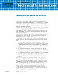
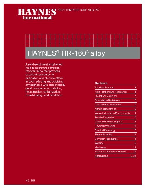
HIGH-TEMPERATURE ALLOYS<br />
HAYNES ® <strong>HR</strong>-160 ® <strong>alloy</strong><br />
A solid-solution-strengthened,<br />
high-temperature corrosionresistant<br />
<strong>alloy</strong> that provides<br />
excellent resistance to<br />
sulfidation and chloride attack<br />
in both reducing and oxidizing<br />
atmospheres with exceptionally<br />
good resistance to oxidation,<br />
hot corrosion, carburization,<br />
metal dusting, and nitridation.<br />
H-3129B<br />
Contents<br />
Principal Features 3<br />
High Temperature Resistance 4<br />
Oxidation Resistance 7<br />
Chloridation Resistance 8<br />
Carburization Resistance 9<br />
Nitriding Resistance 10<br />
Waste <strong>Inc</strong>ineration Environments 11<br />
Tensile Properties 13<br />
Creep and Stress-Rupture 14<br />
Physical Properties 15<br />
Physical Metallurgy 17<br />
Thermal Stability 17<br />
Corrosion Resistance 18<br />
Welding 19<br />
Machining 21<br />
Health and Safety Information 22<br />
Applications 2, 23<br />
HAYNES ® <strong>HR</strong>-160 ® <strong>alloy</strong>
APPLICATIONS<br />
65425<br />
Afterburner retort for processing hazardous<br />
waste.<br />
65425<br />
<strong>HR</strong>-160 ® <strong>alloy</strong> components in petroleum refinery process.<br />
HAYNES ® <strong>HR</strong>-160 ® <strong>alloy</strong> 2<br />
no neg number<br />
assign HI number<br />
Refractory anchors used in waste incinerator<br />
operating between 1300-1700°F (704-927°C)<br />
burning agri-wastes. <strong>HR</strong>-160 ® <strong>alloy</strong> showed the<br />
most resistance in the environment containing<br />
high levels of sulfur and chlorine. Original<br />
material was 309SS.<br />
HI-25 number<br />
Calciner tube made of <strong>HR</strong>-160 ® <strong>alloy</strong> for use in<br />
processing high sulfur feedstocks at 2000°F<br />
(1093°C). <strong>HR</strong>-160 <strong>alloy</strong> was selected after<br />
intensive field rack testing.<br />
© 2004, <strong>Haynes</strong> <strong>International</strong>, <strong>Inc</strong>.
PRINCIPAL FEATURES<br />
Resistance to High-<br />
Temperature Corrosion<br />
HAYNES ® <strong>HR</strong>-160 ® <strong>alloy</strong> is a<br />
solid-solution-strengthened<br />
nickel-cobalt-chromium-silicon<br />
<strong>alloy</strong> with outstanding resistance<br />
to various forms of hightemperature<br />
corrosion attack.<br />
<strong>HR</strong>-160 <strong>alloy</strong> has excellent<br />
resistance to sulfidation and<br />
chloride attack in both reducing<br />
and oxidizing atmospheres.<br />
The <strong>alloy</strong> also has exceptionally<br />
good resistance to oxidation,<br />
hot corrosion, carburization,<br />
metal dusting, nitridation, and<br />
corrosion attack by low melting<br />
point compounds such as those<br />
formed by phosphorus, vanadium,<br />
and other impurities. The<br />
<strong>alloy</strong> is especially suited for<br />
applications in high temperature<br />
corrosive environments generated<br />
by combustion of lowgrade<br />
fuels or processing of<br />
chemical feedstocks with<br />
corrosive contaminants such as<br />
sulfur, chlorine, fluorine, vanadium,<br />
phosphorus, and others.<br />
The <strong>alloy</strong> is capable of withstanding<br />
temperatures up to<br />
2200°F (1204°C).<br />
Ease of Fabrication<br />
HAYNES <strong>HR</strong>-160 <strong>alloy</strong> has<br />
excellent forming and welding<br />
characteristics. It may be<br />
forged or otherwise hot-worked,<br />
providing it is held at 2050°F<br />
(1121°C) for time sufficient to<br />
bring the entire piece to temperature.<br />
As a consequence of<br />
its good ductility, <strong>HR</strong>-160 <strong>alloy</strong><br />
is also readily formed by cold<br />
working. Cold- or hot-worked<br />
parts should be annealed and<br />
rapidly cooled in order to restore<br />
the best balance of properties.<br />
<strong>HR</strong>-160 <strong>alloy</strong> can be welded by<br />
a variety of techniques, including<br />
gas tungsten arc (TIG), gas<br />
metal arc (MIG), and resistance<br />
welding.<br />
Heat-Treatment<br />
<strong>HR</strong>-160 <strong>alloy</strong> is furnished in the<br />
solution annealed condition,<br />
unless otherwise specified. The<br />
<strong>alloy</strong> is solution annealed at<br />
2050°F (1121°C) and rapidly<br />
cooled for optimum properties.<br />
Intermediate annealing, if<br />
required during fabrication and<br />
forming operations, can be<br />
performed at temperatures as<br />
low as 1950°F (1066°C).<br />
Available in Practical<br />
Product Forms<br />
HAYNES <strong>HR</strong>-160 <strong>alloy</strong> is<br />
available in the form of plate,<br />
sheet, strip, billet, bar, wire,<br />
pipe, and tubing.<br />
Nominal Chemical Composition, Weight Percent<br />
3<br />
Applications<br />
HAYNES <strong>HR</strong>-160 <strong>alloy</strong> combines<br />
properties which make it<br />
highly useful for service in<br />
severe high-temperature<br />
corrosive environments. Applications<br />
include a variety of<br />
fabricated components in<br />
municipal, industrial, hazardous,<br />
and nuclear waste incinerators.<br />
It is widely used in recuperators,<br />
heat exchangers and waste<br />
heat recovery systems. <strong>HR</strong>-160<br />
<strong>alloy</strong> is also suitable for utility<br />
boilers, sulfur plants, hightemperature<br />
furnaces, kilns,<br />
calciners, resource recovery<br />
units, cement kilns, pulp and<br />
paper recovery boilers, coal<br />
gasification systems, and<br />
fluidized-bed combustion<br />
systems.<br />
Applicable Specifications<br />
The UNS number for HAYNES<br />
<strong>HR</strong>-160 <strong>alloy</strong> is N12160.<br />
ASME Vessel Code<br />
HAYNES <strong>HR</strong>-160 <strong>alloy</strong> is<br />
covered by ASME Vessel Code<br />
case No. 2162 for Section VIII<br />
Division 1 construction to<br />
1500°F (816°C).<br />
Ni Co Cr Fe Si Mn Ti C W Mo Cb<br />
37 a 29 28 2* 2.75 0.5 0.5 0.05 1* 1* 1*<br />
a As Balance * Maximum<br />
HAYNES ® <strong>HR</strong>-160 ® <strong>alloy</strong>
HIGH TEMPERATURE CORROSION RESISTANCE<br />
Sulfidation in Reducing Atmospheres<br />
Alloy<br />
<strong>alloy</strong> 6B<br />
<strong>HR</strong>-160 <strong>alloy</strong><br />
<strong>alloy</strong> 25<br />
<strong>alloy</strong> 188<br />
<strong>alloy</strong> 150<br />
556 <strong>alloy</strong><br />
Ar-5%H 2 -5%CO-1%CO 2 -0.15%H 2 S (Vol. %)<br />
(PO 2 = 3 x 10 -19 atm, PS 2 = 0.9 x 10 -6 atm)<br />
1600°F (871°C) / 215 hours<br />
52495 47069<br />
47070<br />
<strong>HR</strong>-160 556 <strong>alloy</strong><br />
® <strong>alloy</strong> Alloy 800H<br />
Top edge of the photograph represents the original sample surface. The specimens were tested and<br />
then cathodically descaled to remove the corrosion products prior to mounting for metallography.<br />
% Cobalt<br />
57<br />
30<br />
51<br />
39<br />
50<br />
18<br />
62563<br />
1600°F (871°C) / 500 hours<br />
Metal Loss,<br />
Mils (mm)<br />
0.3 (0.008)<br />
0.2 (0.005)<br />
4.1 (0.10)<br />
7.6 (0.10)<br />
10.3 (0.26)<br />
20.6 (0.52)<br />
62594<br />
<strong>HR</strong>-160 ® <strong>alloy</strong><br />
Note: 1) Nickel <strong>alloy</strong>s (e.g. 600, 601) consumed in 215 hours (0.044-inch thick samples)<br />
2) 310SS suffered 14 mils of attack in 215 hours<br />
3) 800H suffered 19 mils of attack in 215 hours<br />
HAYNES ® <strong>HR</strong>-160 ® <strong>alloy</strong> 4<br />
1600°F (871°C) / 500 hours<br />
Average Depth of Attack<br />
Mils (mm)<br />
3.1 (0.08)<br />
4.7 (0.12)<br />
8.4 (0.21)<br />
14.9 (0.38)<br />
22.1 (0.56)<br />
31.9 (0.81)<br />
62596<br />
slide<br />
17047<br />
RA330 <strong>alloy</strong><br />
Max. Depth of Attack<br />
Mils (mm)<br />
3.3 (0.08)<br />
5.2 (0.13)<br />
14.6 (0.37)<br />
23.6 (0.60)<br />
28.3 (0.72)<br />
35.6 (0.90)
Sulfidation in Reducing Atmospheres<br />
Alloy<br />
<strong>HR</strong>-160 ®<br />
6B<br />
150<br />
25<br />
188<br />
556<br />
1100°F (593°C)<br />
mpy (mm/y)<br />
14.4 (0.37)<br />
23.6 (0.60)<br />
37.7 (0.96)<br />
94.1 (2.39)<br />
150.5 (3.82)<br />
121.1 (3.08)<br />
H 2 -7%CO-1.5%H 2 O-0.6%H 2 S<br />
(PO 2 = 1 x 10 -23 atm, PS 2 = 1 x 10 -9 atm, a C = 0.3-0.4 at 1292°F (700°C))<br />
Note: <strong>HR</strong>-160 <strong>alloy</strong> exhibited about 1.0 mg/cm 2 of weight gain<br />
after 1000 hours of exposure.<br />
H 2 -46%CO-0.8%CO 2 -1.7%H 2 S<br />
5<br />
Total Depth of Attack<br />
1300°F (704°C)<br />
mpy (mm/y)<br />
27.3 (0.70)<br />
264.4 (6.72)<br />
108.8 (2.76)<br />
188.5 (4.79)<br />
292.6 (7.43)<br />
345.8 (8.78)<br />
HAYNES ® <strong>HR</strong>-160 ® <strong>alloy</strong>
Sulfate-Induced Sulfidation in Combustion Atmospheres<br />
Laboratory Hot Corrosion Burner Rig Testing - Specimens were exposed to a combustion stream generated<br />
in a burner rig fired with No. 2 fuel oil with a constant injection of 50 ppm (by weight) salt (mostly<br />
sodium chloride) into the combustion stream. Specimens were also subjected to thermal cycling by<br />
cycling them out of the test chamber once every hour and rapid fan cooling to less than 390°F (199°C) for<br />
two minutes.<br />
310SS<br />
60149<br />
60144<br />
60148<br />
60147<br />
60156<br />
1000<br />
hours<br />
RA330 <strong>alloy</strong> <strong>alloy</strong> 800H <strong>alloy</strong> 625 <strong>HR</strong>-160 ® <strong>alloy</strong><br />
476<br />
hours<br />
62985<br />
62983<br />
62986<br />
62982<br />
62978<br />
62979<br />
No. 2 fuel oil with 0.4% sulfur<br />
1650°F (899°C)<br />
No. 2 fuel oil with 1.0% sulfur<br />
1650°F (899°C) for 500 hours<br />
253 MA ® <strong>alloy</strong> RA330 <strong>alloy</strong> RA85H ® <strong>alloy</strong><br />
HAYNES ® <strong>HR</strong>-160 ® <strong>alloy</strong> 6<br />
1000<br />
hours<br />
940<br />
hours<br />
<strong>alloy</strong> 800H 556 TM <strong>alloy</strong> <strong>HR</strong>-160 ® <strong>alloy</strong><br />
1000<br />
hours
OXIDATION RESISTANCE<br />
Oxidation in Air<br />
Laboratory tests were conducted in flowing air at 1800 to 2200°F (982 to 1204°C) for 1008 hours, with<br />
specimens cycled to room temperature once every 168 hours.<br />
Alloy<br />
<strong>HR</strong>-160 ® <strong>alloy</strong><br />
800HT ® <strong>alloy</strong><br />
253 MA <strong>alloy</strong><br />
RA85H <strong>alloy</strong><br />
Alloy<br />
<strong>HR</strong>-160 <strong>alloy</strong><br />
800HT <strong>alloy</strong><br />
253 MA <strong>alloy</strong><br />
RA85H <strong>alloy</strong><br />
* To convert mils to mm, divide by 40<br />
** Internal oxidation through thickness<br />
Metal Loss,<br />
Mils*<br />
0.6<br />
0.0<br />
1.3<br />
0.5<br />
Metal Loss,<br />
Mils*<br />
2.7<br />
12.3<br />
8.4<br />
3.7<br />
Long-Term Oxidation in Air<br />
1800°F (982°C)<br />
Average Metal<br />
Affected, Mils*<br />
5.9<br />
3.9<br />
2.9<br />
8.2<br />
7<br />
Metal Loss<br />
Mils*<br />
1.7<br />
6.1<br />
0.7<br />
2.9<br />
2000°F (1093°C)<br />
2100°F (1149°C) 2200°F (1204°C)<br />
Average Metal<br />
Affected, Mils*<br />
13.0<br />
18.8<br />
16.4<br />
>59**<br />
Metal Loss<br />
Mils*<br />
4.1<br />
19.4<br />
18.6<br />
3.9<br />
Average Metal<br />
Affected, Mils*<br />
10.3<br />
12.0<br />
8.2<br />
25.9<br />
Average Metal<br />
Affected, Mils*<br />
24.2<br />
>58*<br />
29.2<br />
>59**<br />
Laboratory tests were conducted at 2000°F (1093°C) in still air (box furnace), with specimens being<br />
cycled to room temperature once every 30 days.<br />
Alloy<br />
<strong>HR</strong>-160 <strong>alloy</strong><br />
<strong>alloy</strong> 601<br />
800HT <strong>alloy</strong><br />
RA85H <strong>alloy</strong><br />
* 360 days<br />
30<br />
days<br />
10.4<br />
4.6<br />
4.6<br />
6.3<br />
90<br />
days<br />
23.2<br />
15.8<br />
203.3<br />
46.5<br />
Weight Loss (mg/cm 2 )<br />
150<br />
days<br />
34.6<br />
28.2<br />
379.7<br />
103.8<br />
210<br />
days<br />
46.8<br />
46.1<br />
529.2<br />
144.9<br />
300<br />
days<br />
60.1<br />
82.0<br />
746.7<br />
210.5<br />
360<br />
days<br />
73.1<br />
110.5<br />
893.9<br />
348.1<br />
Metal Loss*<br />
Mils<br />
3.6<br />
5.4<br />
44.3<br />
17.9<br />
Average Metal*<br />
Affected, Mils<br />
29.0<br />
45.1<br />
51.0<br />
80.3<br />
HAYNES ® <strong>HR</strong>-160 ® <strong>alloy</strong>
CHLORIDATION RESISTANCE<br />
High Temperature Chloride Vapor Corrosion<br />
Chlorination Resistance<br />
Alloy<br />
214 <strong>alloy</strong><br />
<strong>HR</strong>-160 ® <strong>alloy</strong><br />
<strong>alloy</strong> 800H<br />
Ar-20%0 2 -2%H 2 O-0.05%NaCl (Vol.%)<br />
1830°F (999°C) for 75 hours<br />
HAYNES ® <strong>HR</strong>-160 ® <strong>alloy</strong> 8<br />
Total Depth of Attack, Mils (mm)<br />
11.5 (0.29)<br />
12.0 (0.31)<br />
>62.0 (complete penetration)<br />
Field tests were conducted by exposing specimens to air containing vapors of sodium chloride,<br />
potassium chloride and barium chloride at 1600°F (871°C) for 173 hours.<br />
<strong>HR</strong>-160 <strong>alloy</strong> 188<br />
® <strong>alloy</strong> Type 310 SS<br />
65276<br />
Maximal loss of sound metal per side.<br />
Laboratory tests in chlorinating atmospheres<br />
at 1112°F (600°C) for 500 hours.*<br />
Maximal loss of sound metal per side.<br />
Laboratory tests in oxychlorinating atmospheres<br />
at 1112°F (600°C) for 500 hours.*<br />
*Data from "Corrosion Studies and Recommendation of Alloys for an <strong>Inc</strong>inerator of Glove-Boxes Wastes" by F. Devisme and<br />
N. H. Garnier, Presented at the 11th <strong>International</strong> <strong>Inc</strong>ineration Conference 1992, May 11-15, 1992, Albuquerque, New Mexico.
CARBURIZATION RESISTANCE<br />
Laboratory pack carburization testing in graphite at 1800°F (982°C) for 500 hours<br />
Alloy<br />
<strong>HR</strong>-120 ® <strong>alloy</strong><br />
556 <strong>alloy</strong><br />
<strong>HR</strong>-160 ® <strong>alloy</strong><br />
800HT <strong>alloy</strong><br />
<strong>alloy</strong> 601<br />
RA330 <strong>alloy</strong><br />
310SS<br />
253 MA <strong>alloy</strong><br />
Alloy<br />
<strong>HR</strong>-160 <strong>alloy</strong><br />
<strong>alloy</strong> 601<br />
<strong>alloy</strong> 800H<br />
<strong>alloy</strong> 600<br />
<strong>HR</strong>-120 <strong>alloy</strong><br />
556 <strong>alloy</strong><br />
RA330 <strong>alloy</strong><br />
253 MA <strong>alloy</strong><br />
310SS<br />
Carbon Absorption<br />
(mg/cm 2 )<br />
0.0<br />
0.0<br />
0.3<br />
0.3<br />
1.0<br />
1.9<br />
7.7<br />
11.6<br />
9<br />
Depth of Carburization<br />
Mils (mm)<br />
0<br />
0<br />
0<br />
0.9 (0.02)<br />
18.0 (0.46)<br />
70.6 (1.79)<br />
84.2 (2.14)<br />
92.1 (2.34)<br />
Field tests conducted in a carbon bed<br />
during manufacturing of activated carbon<br />
at 1650°F (899°C) for 120 hours<br />
57409<br />
<strong>HR</strong>-160 ® <strong>alloy</strong><br />
57542<br />
Type 316 SS<br />
Ar-5%H 2 -1%CH 4 (Vol.%)<br />
1800°F (982°C) for 55 hours<br />
Carbon Absorption<br />
(mg/cm 2 )<br />
2.9<br />
3.2<br />
3.6<br />
7.3<br />
7.9<br />
7.9<br />
9.2<br />
9.4<br />
10.0<br />
HAYNES ® <strong>HR</strong>-160 ® <strong>alloy</strong>
NITRIDATION RESISTANCE<br />
HAYNES ® <strong>HR</strong>-160 ® <strong>alloy</strong> is also very resistant to nitridation attack. Tests were performed in flowing<br />
ammonia or nitrogen at various temperatures for 168 hours. Nitrogen absorption was determined by<br />
chemical analysis of samples before and after exposure and knowledge of the exposed specimen area.<br />
Alloy<br />
<strong>HR</strong>-160 <strong>alloy</strong><br />
<strong>alloy</strong> 601<br />
RA330 <strong>alloy</strong><br />
<strong>alloy</strong> 800H<br />
304SS<br />
316SS<br />
310SS<br />
446SS<br />
253 MA <strong>alloy</strong><br />
Alloy<br />
<strong>HR</strong>-160 <strong>alloy</strong><br />
<strong>alloy</strong> 601<br />
RA330 <strong>alloy</strong><br />
RA85H <strong>alloy</strong><br />
253 MA <strong>alloy</strong><br />
<strong>alloy</strong> 800H<br />
<strong>alloy</strong> 800HT<br />
310SS<br />
1200°F (649°C)<br />
0.9<br />
1.1<br />
4.7<br />
4.3<br />
9.8<br />
6.9<br />
7.4<br />
28.8<br />
HAYNES ® <strong>HR</strong>-160 ® <strong>alloy</strong> 10<br />
-<br />
Ammonia (NH 3 )<br />
168 hours<br />
Nitrogen Absorption (mg/cm 2 )<br />
1800°F (982°C)<br />
2.2<br />
1.2<br />
3.9<br />
4.0<br />
7.3<br />
6.0<br />
7.7<br />
12.9<br />
3.3<br />
Nitrogen (N 2 )<br />
2000°F (1093°C), 168 hours<br />
Nitrogen Absorption (mg/cm 2 )<br />
3.9<br />
7.2<br />
6.6<br />
8.5<br />
10.0<br />
10.3<br />
11.4<br />
12.3<br />
2000°F (1093°C)<br />
3.0<br />
2.6<br />
3.1<br />
5.5<br />
3.5<br />
3.3<br />
9.5<br />
4.5<br />
6.3
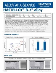
WASTE INCINERATION ENVIRONMENTS<br />
<strong>Inc</strong>ineration of municipal, industrial and hazardous wastes generates very corrosive environments which<br />
typically contain such corrosive constituents as SO 2 , HCl and sometimes HF, along with vapors/deposits<br />
of chlorides and sulfates. The following examples demonstrate the relative improvements resulting from<br />
upgrading to <strong>HR</strong>-160 ® <strong>alloy</strong>.<br />
Type 446 SS<br />
Soot blowers in a municipal waste incinerator<br />
1400°F (760°C) for 75 days<br />
PHOTOS<br />
GYL SLIDE<br />
18172<br />
Thermowell in municipal waste incinerator<br />
1800-2100°F (982-1149°C) for 180 days<br />
PHOTOS<br />
GYL SLIDE<br />
18170<br />
<strong>HR</strong>-160 ® <strong>alloy</strong><br />
11<br />
<strong>HR</strong>-160 ® <strong>alloy</strong><br />
HAYNES ® <strong>HR</strong>-160 ® <strong>alloy</strong>
Waste <strong>Inc</strong>ineration Environments<br />
HAYNES ® <strong>HR</strong>-160 ® thermowell in a municipal waste incinerator for<br />
170 days at 1850-1950°F (1010-1066°C)<br />
Unexposed end Exposed end<br />
65847<br />
PHOTOS<br />
GYL SLIDE<br />
18171<br />
Field testing in a chemical waste incinerator showed little scaling or metal wastage for <strong>HR</strong>-160 <strong>alloy</strong><br />
when exposed to the flue gas stream which contained SO 2 , HCl and HF for 5800 hours at 900°F<br />
(482°C)<br />
<strong>HR</strong>-160 ® <strong>alloy</strong> <strong>alloy</strong> 600<br />
66614<br />
HAYNES ® <strong>HR</strong>-160 ® <strong>alloy</strong> 12<br />
66615
TYPICAL TENSILE PROPERTIES<br />
Tensile Data (plate)*<br />
Test<br />
Temperature<br />
°F (°C)<br />
70 (21)<br />
200 (93)<br />
400 (204)<br />
600 (316)<br />
800 (427)<br />
1000 (538)<br />
1200 (649)<br />
1400 (760)<br />
1600 (871)<br />
1800 (982)<br />
2000 (1093)<br />
2100 (1149)<br />
2200 (1204)<br />
* Hot-Rolled and Solution-Annealed<br />
Tensile Data (Sheet)*<br />
* Solution-Annealed<br />
Test<br />
Temperature<br />
°F (°C)<br />
70 (21)<br />
1000 (538)<br />
1200 (649)<br />
1400 (760)<br />
1600 (871)<br />
1800 (982)<br />
2000 (1093)<br />
2100 (1149)<br />
2200 (1204)<br />
Ultimate<br />
Tensile<br />
Strength<br />
Ksi MPa<br />
111.2 767<br />
104.0 717<br />
97.9 675<br />
91.9 634<br />
87.7 605<br />
81.8 564<br />
75.8 523<br />
62.1 428<br />
38.3 264<br />
20.4 140<br />
10.8 74<br />
6.0 41<br />
4.4 30<br />
Ultimate<br />
Tensile<br />
Strength<br />
Ksi MPa<br />
110.0 758<br />
82.5 569<br />
75.3 519<br />
61.1 421<br />
34.9 241<br />
18.7 129<br />
9.8 68<br />
6.6 46<br />
4.8 33<br />
Yield Strength<br />
at 0.2% Offset<br />
Ksi MPa<br />
45.6 314<br />
40.4 279<br />
33.8 233<br />
27.6 190<br />
26.0 179<br />
25.5 176<br />
25.7 177<br />
24.7 170<br />
22.1 152<br />
10.8 74<br />
5.0 34<br />
2.3 16<br />
1.6 11<br />
13<br />
Yield Strength<br />
at 0.2% Offset<br />
Ksi MPa<br />
51.2 353<br />
32.7 225<br />
31.2 215<br />
30.7 212<br />
15.9 110<br />
9.5 66<br />
4.7 32<br />
2.8 19<br />
2.0 14<br />
Elongation in<br />
1.340 in. (34.0 mm)<br />
%<br />
68<br />
69<br />
71<br />
74<br />
76<br />
76<br />
70<br />
73<br />
85<br />
90<br />
88<br />
113<br />
110<br />
Elongation in<br />
2 in. (50.8 mm)<br />
%<br />
63<br />
73<br />
62<br />
47<br />
41<br />
51<br />
53<br />
107<br />
91<br />
Reduction<br />
of Area<br />
%<br />
73<br />
74<br />
74<br />
70<br />
68<br />
69<br />
67<br />
64<br />
84<br />
98<br />
98<br />
94<br />
94<br />
HAYNES ® <strong>HR</strong>-160 ® <strong>alloy</strong>
CREEP AND STRESS-RUPTURE STRENGTHS<br />
Plate - 2050°F (1121°C) Solution Anneal<br />
Temperature<br />
°F (°C)<br />
1100 593<br />
1200 649<br />
1300 704<br />
1400 760<br />
1500 816<br />
1600 871<br />
1700 927<br />
1800 982<br />
* Extrapolation<br />
Creep Percent<br />
1.0<br />
Rupture<br />
1.0<br />
Rupture<br />
1.0<br />
Rupture<br />
1.0<br />
Rupture<br />
1.0<br />
Rupture<br />
1.0<br />
Rupture<br />
1.0<br />
Rupture<br />
1.0<br />
Rupture<br />
100 Hours<br />
29.4 (203)<br />
45.5 (315)<br />
18.9 (131)<br />
32.2 (223)<br />
12.5 (86)<br />
22.9 (158)<br />
8.5 (59)<br />
16.4 (113)<br />
5.9 (41)<br />
11.7 (81)<br />
4.2 (29)<br />
8.4 (58)<br />
3.0 (21)<br />
6.1 (42)<br />
2.2 (15)<br />
4.4 (30)<br />
Comparative Stress-Rupture Strengths<br />
Temperature<br />
°F (°C)<br />
1200 649<br />
1300 704<br />
1400 760<br />
1500 816<br />
1600 871<br />
1700 927<br />
1800 982<br />
Temperature<br />
°F (°C)<br />
1200 649<br />
1300 704<br />
1400 760<br />
1500 816<br />
1600 871<br />
1700 927<br />
1800 982<br />
<strong>HR</strong>-160 ®<br />
15.6<br />
10.8<br />
7.4<br />
5.1<br />
3.6<br />
2.5<br />
1.8<br />
<strong>HR</strong>-160**<br />
11.0<br />
7.4<br />
5.0<br />
3.4<br />
2.4<br />
1.6<br />
1.2<br />
RA333 ®<br />
16.5<br />
12.0<br />
9.2<br />
5.7<br />
3.1<br />
1.8<br />
1.05<br />
11.5<br />
8.4<br />
6.5<br />
3.7<br />
1.9<br />
1.05<br />
0.58<br />
13.0<br />
* Ksi can be converted to MPa (megapascals) by multiplying by 6.895<br />
** Extrapolation<br />
8.0<br />
5.3<br />
3.7<br />
2.5<br />
1.2<br />
0.8<br />
HAYNES ® <strong>HR</strong>-160 ® <strong>alloy</strong> 14<br />
Approximate Initial Stress, Ksi (MPa)<br />
to Produce Specified Creep in<br />
1000 Hours<br />
20.4 (141)<br />
32.2 (223)<br />
13.1 (91)<br />
22.4 (154)<br />
8.7 (60)<br />
15.7 (108)<br />
6.0 (41)<br />
11.0 (76)<br />
4.1 (28)<br />
7.7 (53)<br />
2.9 (20)<br />
5.5 (38)<br />
2.1 (14)<br />
3.9 (27)<br />
1.5 (10)<br />
2.8 (19)<br />
7.6<br />
-<br />
2.7<br />
-<br />
1.0<br />
-<br />
0.33<br />
10,000 Hours<br />
14.4* (100)<br />
22.9 (158)<br />
9.3* (64)<br />
15.6 (108)<br />
6.2* (43)<br />
10.8 (75)<br />
4.2* (29)<br />
7.4 (51)<br />
2.9* (20)<br />
5.1 (35)<br />
2.1* (14)<br />
3.6 (25)<br />
1.5* (10)<br />
2.5 (17)<br />
1.1* (8)<br />
1.8 (12)<br />
10,000 Hours Rupture Strenths (Ksi*)<br />
800HT<br />
17.5<br />
11.0<br />
7.3<br />
5.2<br />
3.5<br />
1.9<br />
1.2<br />
RA330<br />
11.0<br />
-<br />
4.3<br />
-<br />
1.7<br />
-<br />
0.63<br />
253 MA<br />
14.0<br />
8.5<br />
5.2<br />
3.75<br />
2.5<br />
1.65<br />
1.15<br />
100,000 Hours Rupture Strenths (Ksi*)<br />
RA333 800HT RA330 253 MA RA85H<br />
8.7<br />
4.6<br />
3.9<br />
2.1<br />
1.45<br />
0.97<br />
0.7<br />
RA85H<br />
12.0<br />
-<br />
5.0<br />
-<br />
2.1<br />
-<br />
0.9<br />
8.0<br />
-<br />
3.2<br />
-<br />
1.3<br />
-<br />
0.5<br />
309<br />
309<br />
11.6<br />
-<br />
100,000 Hours*<br />
16.0<br />
-<br />
5.45<br />
-<br />
1.86<br />
-<br />
0.63<br />
- -<br />
16.3 (113)<br />
- -<br />
11.0 (76)<br />
- -<br />
7.4 (51)<br />
- -<br />
5.0 (34)<br />
- -<br />
3.4 (23)<br />
- -<br />
2.4 (17)<br />
- -<br />
1.6 (11)<br />
- -<br />
1.2 (8)<br />
3.8<br />
-<br />
1.25<br />
-<br />
0.41<br />
310<br />
9.3<br />
-<br />
3.9<br />
-<br />
1.65<br />
-<br />
0.69<br />
310<br />
6.5<br />
-<br />
2.6<br />
-<br />
1.06<br />
-<br />
0.42
TYPICAL PHYSICAL PROPERTIES<br />
Temp., °F British Units Temp., °C Metric Units<br />
Density Room 0.292 lb/in. 3 Room 8.08 g/cm. 3<br />
Melting Temperature 2360-2500 1293-1370<br />
Electrical Resistivity Room 43.8 microhm-in. Room 111.2 microhm-cm<br />
200 44.3 microhm-in. 100 112.8 microhm-cm<br />
400 45.2 microhm-in. 200 114.7 microhm-cm<br />
600 46.1 microhm-in. 300 116.7 microhm-cm<br />
800 46.9 microhm-in. 400 118.6 microhm-cm<br />
1000 47.8 microhm-in. 500 120.6 microhm-cm<br />
1200 48.3 microhm-in. 600 122.4 microhm-cm<br />
1400 48.6 microhm-in. 700 123.1 microhm-cm<br />
1600 48.9 microhm-in. 800 123.8 microhm-cm<br />
1800 49.3 microhm-in. 900 124.5 microhm-cm<br />
2000 49.6 microhm-in. 1000 125.2 microhm-cm<br />
2200 49.9 microhm-in. 1100 125.9 microhm-cm<br />
1200 126.7 microhm-cm<br />
Thermal Diffusivity Room 4.6 x 10 -3 in. 2 /sec. Room 29.4 x 10 -3 cm 2 /sec.<br />
212 4.8 x 10 -3 in. 2 /sec. 100 30.8 x 10 -3 cm 2 /sec.<br />
392 5.2 x 10 -3 in. 2 /sec. 200 33.6 x 10 -3 cm 2 /sec.<br />
572 5.7 x 10 -3 in. 2 /sec. 300 37.0 x 10 -3 cm 2 /sec.<br />
752 6.3 x 10 -3 in. 2 /sec. 400 40.6 x 10 -3 cm 2 /sec.<br />
932 6.9 x 10 -3 in. 2 /sec. 500 44.3 x 10 -3 cm 2 /sec.<br />
1112 7.1 x 10 -3 in. 2 /sec. 600 45.6 x 10 -3 cm 2 /sec.<br />
1292 7.3 x 10 -3 in. 2 /sec. 700 47.2 x 10 -3 cm 2 /sec.<br />
1472 7.5 x 10 -3 in. 2 /sec. 800 48.6 x 10 -3 cm 2 /sec.<br />
1652 7.5 x 10 -3 in. 2 /sec. 900 48.7 x 10 -3 cm 2 /sec.<br />
1832 7.9 x 10 -3 in. 2 /sec. 1000 50.9 x 10 -3 cm 2 /sec.<br />
2012 8.4 x 10 -3 in. 2 /sec. 1100 54.1 x 10 -3 cm 2 /sec.<br />
2192 8.7 x 10 -3 in. 2 /sec. 1200 56.1 x 10 -3 cm 2 /sec.<br />
Thermal Conductivity Room 75 Btu-in./ft. 2 hr.-°F Room 10.9 W/m-K<br />
200 82 Btu-in./ft. 2 hr.-°F 100 12.0 W/m-K<br />
400 95 Btu-in./ft. 2 hr.-°F 200 13.6 W/m-K<br />
600 108 Btu-in./ft. 2 hr.-°F 300 15.4 W/m-K<br />
800 126 Btu-in./ft. 2 hr.-°F 400 17.6 W/m-K<br />
1000 144 Btu-in./ft. 2 hr.-°F 500 19.9 W/m-K<br />
1200 162 Btu-in./ft. 2 hr.-°F 600 21.8 W/m-K<br />
1400 178 Btu-in./ft. 2 hr.-°F 700 24.7 W/m-K<br />
1600 185 Btu-in./ft. 2 hr.-°F 800 26.1 W/m-K<br />
1800 196 Btu-in./ft. 2 hr.-°F 900 26.9 W/m-K<br />
2000 213 Btu-in./ft. 2 hr.-°F 1000 28.7 W/m-K<br />
2200 228 Btu-in./ft. 2 hr.-°F 1100 31.1 W/m-K<br />
1200 32.9 W/m-K<br />
15<br />
HAYNES ® <strong>HR</strong>-160 ® <strong>alloy</strong>
Typical Physical Properties<br />
Specific Heat Room 0.110 Btu/lb.-°F Room 462 J/Kg-K<br />
200 0.116 Btu/lb.-°F 100 487 J/Kg-K<br />
400 0.121 Btu/lb.-°F 200 506 J/Kg-K<br />
600 0.125 Btu/lb.-°F 300 521 J/Kg-K<br />
800 0.131 Btu/lb.-°F 400 542 J/Kg-K<br />
1000 0.136 Btu/lb.-°F 500 562 J/Kg-K<br />
1200 0.151 Btu/lb.-°F 600 597 J/Kg-K<br />
1400 0.159 Btu/lb.-°F 700 653 J/Kg-K<br />
1600 0.164 Btu/lb.-°F 800 672 J/Kg-K<br />
1800 0.167 Btu/lb.-°F 900 689 J/Kg-K<br />
2000 0.171 Btu/lb.-°F 1000 704 J/Kg-K<br />
2200 0.175 Btu/lb.-°F 1100 719 J/Kg-K<br />
1200 732 J/Kg-K<br />
HAYNES ® <strong>HR</strong>-160 ® <strong>alloy</strong> 16<br />
Temp., °F British Units Temp., °C Metric Units<br />
Dynamic Modulus of Room 30.6 x 10 6 psi Room 211 GPa<br />
Elasticity 100 30.5 x 10 6 psi 40 210 GPa<br />
200 30.1 x 10 6 psi 90 208 GPa<br />
300 29.6 x 10 6 psi 150 204 GPa<br />
400 29.1 x 10 6 psi 205 201 GPa<br />
500 28.6 x 10 6 psi 260 197 GPa<br />
600 27.8 x 10 6 psi 315 192 GPa<br />
700 27.1 x 10 6 psi 370 187 GPa<br />
800 26.5 x 10 6 psi 425 183 GPa<br />
900 26.1 x 10 6 psi 480 180 GPa<br />
1000 25.6 x 10 6 psi 540 177 GPa<br />
1100 25.1 x 10 6 psi 595 173 GPa<br />
1200 24.4 x 10 6 psi 650 168 GPa<br />
1300 23.7 x 10 6 psi 705 163 GPa<br />
1400 22.9 x 10 6 psi 760 158 GPa<br />
1500 22.4 x 10 6 psi 815 154 GPa<br />
1600 21.7 x 10 6 psi 870 150 GPa<br />
1700 21.1 x 10 6 psi 925 145 GPa<br />
1800 19.8 x 10 6 psi 980 137 GPa<br />
Mean Coefficient of 78-200 7.2 microinches/in.-°F 25-95 13.0 10 -6 m/m-°C<br />
Thermal Expansion 78-400 7.6 microinches/in.-°F 25-205 13.7 10 -6 m/m-°C<br />
78-600 7.9 microinches/in.-°F 25-315 14.0 10 -6 m/m-°C<br />
78-800 8.1 microinches/in.-°F 25-425 14.4 10 -6 m/m-°C<br />
78-1000 8.3 microinches/in.-°F 25-540 14.9 10 -6 m/m-°C<br />
78-1200 8.6 microinches/in.-°F 25-600 15.5 10 -6 m/m-°C<br />
78-1400 8.9 microinches/in.-°F 25-700 15.7 10 -6 m/m-°C<br />
78-1600 9.2 microinches/in.-°F 25-800 16.6 10 -6 m/m-°C<br />
78-1800 9.5 microinches/in.-°F 25-900 17.1 10 -6 m/m-°C
PHYSICAL METALLURGY<br />
Typical Grain Size<br />
Average Hardness<br />
64420<br />
Annealed Microstructure<br />
THERMAL STABILITY<br />
Annealed<br />
Thermal<br />
Exposure<br />
Condition*<br />
Aged at 1200°F/1000 hrs<br />
Aged at 1200°F/4000 hrs<br />
Aged at 1200°F/8000 hrs<br />
Aged at 1400°F/1000 hrs<br />
Aged at 1400°F/4000 hrs<br />
Aged at 1400°F/8000 hrs<br />
Aged at 1600°F/1000 hrs<br />
Aged at 1600°F/4000 hrs<br />
Aged at 1600°F/8000 hrs<br />
* Plate<br />
17<br />
Plate/Bar<br />
1 1/2 - 2 1/2<br />
Rb 88<br />
Room-Temperature Tensile Properties<br />
Ultimate<br />
Tensile<br />
Strength<br />
Ksi MPa<br />
112.2 774<br />
117.8 812<br />
121.5 838<br />
122.2 843<br />
115.0 793<br />
117.3 809<br />
116.0 800<br />
101.6 701<br />
98.0 676<br />
91.7 632<br />
Sheet<br />
3 1/2 - 4<br />
Rb 87<br />
The <strong>alloy</strong> has a stable austenitic structure<br />
and exhibits no sigma or mu phases after<br />
long-term aging. Aging at 1200, 1400 and<br />
1600°F (649, 760 and 871°C) for 4000<br />
hours, for example, resulted in the precipitation<br />
of Cr 23 C 6 and G phase (Ni 16 Ti 6 Si 7 ).<br />
The morphology of G phase is quite<br />
similar to that of Cr 23 C 6 . Thus, G phase is<br />
not considered to be more detrimental<br />
than carbides in causing the ductility to<br />
drop upon long-term aging. The <strong>alloy</strong> is<br />
non-magnetic in annealed and coldworked<br />
conditions.<br />
Yield Strength<br />
at 0.2% Offset<br />
Ksi MPa<br />
46.5 321<br />
49.5 341<br />
51.3 354<br />
51.2 353<br />
46.4 320<br />
46.6 321<br />
46.2 319<br />
42.9 295<br />
43.1 297<br />
42.0 290<br />
Elongation in<br />
2 in. (50.8 mm)<br />
%<br />
66<br />
40<br />
38<br />
34<br />
36<br />
26<br />
26<br />
28<br />
24<br />
20<br />
Reduction<br />
Area<br />
%<br />
73<br />
33<br />
31<br />
28<br />
28<br />
23<br />
19<br />
23<br />
20<br />
16<br />
HAYNES ® <strong>HR</strong>-160 ® <strong>alloy</strong>
Thermal Stability<br />
3% HCl + 59% HNO 3 , 80°C<br />
1% HF + 20% HNO 3 , 80°C<br />
50% H 2 SO 4 + 10% HNO 3 , Boiling<br />
60% H 2 SO 4 + 5% HNO 3 , Boiling<br />
65% HNO 3 , Boiling<br />
50% H 2 SO 4 + 42 g/l Fe 2 (SO 4 ) 3<br />
G-28A, Boiling<br />
25% H 2 SO 4 + 5% HNO 3 +<br />
4% NaCl, Boiling<br />
1% HCl, Boiling<br />
1% HCl + 1% H 2 SO 4 +<br />
1% HF, 79°C<br />
Annealed<br />
HAYNES ® <strong>HR</strong>-160 ® <strong>alloy</strong><br />
Condition<br />
Aged at 1200°F/1000 hrs<br />
Aged at 1200°F/4000 hrs<br />
Aged at 1200°F/8000 hrs<br />
Aged at 1400°F/1000 hrs<br />
Aged at 1400°F/4000 hrs<br />
Aged at 1400°F/8000 hrs<br />
Aged at 1600°F/1000 hrs<br />
Aged at 1600°F/4000 hrs<br />
Aged at 1600°F/8000 hrs<br />
18<br />
Room-Temperature<br />
V-Notch Impact Strength<br />
ft.-lb.<br />
264<br />
AQUEOUS CORROSION RESISTANCE<br />
Stress Corrosion Cracking<br />
Uniform Corrosion<br />
Alloy<br />
<strong>HR</strong>-160 ® <strong>alloy</strong><br />
C-22 ® <strong>alloy</strong><br />
<strong>alloy</strong> 825<br />
316LSS<br />
*To convert mils per year (mpy) to mm per year, divide by 40.<br />
43<br />
34<br />
31<br />
27<br />
18<br />
15<br />
16<br />
13<br />
11<br />
U-Bend Specimens<br />
45% MgCl 2 , 154°C (309°F)<br />
Joules<br />
358<br />
58<br />
46<br />
42<br />
37<br />
24<br />
20<br />
22<br />
18<br />
15<br />
Average Corrosion Rate Per Year, mils*<br />
<strong>HR</strong>-160<br />
2<br />
35<br />
20<br />
50<br />
9<br />
9<br />
3<br />
469<br />
107<br />
Time to Failure, hours<br />
1000 No cracking<br />
1000 No cracking<br />
150 Cracked<br />
24 Cracked<br />
625<br />
20<br />
123<br />
-<br />
105<br />
20<br />
24<br />
713<br />
120<br />
0.9<br />
316L<br />
-<br />
>400<br />
-<br />
-<br />
12<br />
38<br />
-<br />
524<br />
245
WELDING<br />
HAYNES ® <strong>HR</strong>-160 ® <strong>alloy</strong> is<br />
readily weldable by Gas Tungsten<br />
Arc (TIG) and Gas Metal<br />
Arc (MIG) welding processes.<br />
Many of the <strong>alloy</strong>'s welding<br />
characteristics are similar to<br />
those for the HASTELLOY ®<br />
<strong>alloy</strong>s and the same precautions<br />
apply. Submerged arc<br />
welding is not recommended as<br />
this process is characterized by<br />
high heat input which could<br />
result in distortion and hot<br />
cracking. <strong>HR</strong>-160 filler metal is<br />
prone to start/stop cracking.<br />
The filler metal may be prone to<br />
hot cracking when welding<br />
heavy plate (e.g. greater than<br />
1/2 inch thick) under highly<br />
restrained conditions. Any<br />
localized cracking should be<br />
removed by grinding prior to<br />
further welding. Do not attempt<br />
to remelt or "wash-out" welding<br />
cracks.<br />
Manual Gas Tungsten Arc Welding<br />
Base Metal Preparation<br />
The joint surface and adjacent<br />
area should be thoroughly<br />
cleaned before welding. All<br />
grease, oil, crayon marks, sulfur<br />
compounds and other foreign<br />
matter should be removed. It is<br />
preferable, but not mandatory,<br />
that the <strong>alloy</strong> be in the solutionannealed<br />
condition when<br />
welded.<br />
Filler Metal Selection<br />
Matching composition filler<br />
metal is recommended for<br />
joining <strong>HR</strong>-160 <strong>alloy</strong>. When<br />
dissimilar base metals are to be<br />
jointed, such as <strong>HR</strong>-160 <strong>alloy</strong> to<br />
a stainless steel, HAYNES 556<br />
filler metal is recommended.<br />
Preheating, Interpass<br />
Temperatures and Post-<br />
Weld Heat Treatment<br />
Preheat should not be used so<br />
long as the base metal to<br />
V- or U-Groove - All Thicknesses 0.125" (3.2 mm) or greater<br />
Technique - Stringer Bead<br />
Current (DCEN), amperes - 120 root, 150 fill<br />
Voltage - 10 to 14<br />
Filler Metal - 0.125" (3.2 mm) diameter. <strong>HR</strong>-160 wire<br />
Travel Speed, ipm (mm/min) - 4 to 6 (100-150)<br />
Electrode Size-EWTH-2, in (mm) - 0.125 (3.2)<br />
Electrode Shape - 30° included angle<br />
Cup Size - #8 or larger<br />
Shielding Gas, 100% Ar CFH (l/min.) - 30 to 35<br />
Backup Gas, 100% Ar CFH (l/min.) - 10 CFH<br />
Preheat - Ambient<br />
Interpass Temperature -
Gas Metal Arc Welding<br />
Short Circuiting Transfer Mode<br />
All Thicknesses 0.125" (3.2 mm) or greater<br />
Technique - Stringer or slight weave<br />
Current (DCEN), amperes - 100 to 140<br />
Voltage - 18 to 21<br />
Wire Feed Rate, ipm (m/min) - 170 to 190 (4.3 to 4.8)<br />
Stickout, in (mm) - 0.5 to 0.75 (12.7 to 19)<br />
Filler Metal - 0.045" (1.1 mm) diameter <strong>HR</strong>-160 wire<br />
Travel Speed, ipm (mm/min - 8 to 14 (203 to 356)<br />
Shielding Gas Flow, CFH (l/min.) - 50 (23.7)<br />
Gas - Argon - 25% Helium<br />
NO NEG NUMBER<br />
ASSIGN HI# Large Welded retort<br />
fabricated from<br />
0.375 inch (9.5 mm)<br />
<strong>HR</strong>-160 ® plate<br />
NEG. NUM-<br />
BER 60606<br />
HAYNES ® <strong>HR</strong>-160 ® <strong>alloy</strong> 20<br />
Typical face, root and side<br />
bends for <strong>HR</strong>-160 <strong>alloy</strong>. The<br />
plate thickness was 0.5 inch<br />
(12.7 mm) and the bend<br />
radius 1.0 inch (25 mm) (2T<br />
radius)
MACHINING<br />
HAYNES ® <strong>HR</strong>-160 ® <strong>alloy</strong> is<br />
similar in machining characteristics<br />
to other solid-solutionstrengthened<br />
nickel-base <strong>alloy</strong>s.<br />
These <strong>alloy</strong>s as a group are<br />
classified as moderate to<br />
difficult to machine; however,<br />
Normal Roughing (Turning / Facing)<br />
Use carbide C-2 / C-3 grade tool<br />
Speed: 90 surface feet / minute<br />
Feed: 0.010 in. / revolution<br />
Depth of cut: 0.150 in.<br />
Finishing (Turning / Facing)<br />
Use carbide C-2 / C-3 grade tool<br />
Speed: 95-110 surface feet / minute<br />
Feed: 0.005-0.007 in. / revolution<br />
Depth of cut: 0.040 in.<br />
Drilling<br />
Use high speed steel M-33 / M-40 series 6 / or T-<br />
15 grades*<br />
Speed: 10-15 surface feet / minute (200 RPM<br />
maximum for 1/4 in. diameter or smaller)<br />
Lubricant: oil or water-base. Use coolant feed<br />
drills if possible.<br />
it should be emphasized that<br />
they can be machined using<br />
conventional methods at<br />
satisfactory rates. As these<br />
<strong>alloy</strong>s will work-harden rapidly,<br />
the keys to successful machining<br />
are to use lower speeds and<br />
21<br />
feeds, and to take heavier cuts<br />
than would be used for machining<br />
stainless steels. See<br />
<strong>Haynes</strong> <strong>International</strong> publication<br />
H-3159 for more detailed<br />
information.<br />
Negative rake square insert, 45° SCEA 1<br />
1/32 in. nose radius. Tool holder: 5° negative<br />
back and side rakes.<br />
Lubricant: Dry 2 , oil 3 or water-base 4,5 .<br />
Positive rake square insert, if possible,<br />
45° SCEA 1 1/32 in. nose radius. Tool holder:<br />
5° positive back and side rakes.<br />
Lubricant: Dry or water-base.<br />
Short, heavy-web drills with 135° crank shaft<br />
point. Thinning of web at point may reduce<br />
thrust.<br />
Feed:<br />
0.001 in. rev. 1/8 in. dia.<br />
0.002 in. rev. 1/4 in. dia.<br />
0.003 in. rev. 1/2 in. dia.<br />
0.005 in. rev. 3/4 in. dia.<br />
0.007 in. rev. 1 in. dia.<br />
*Carbide drills not recommended, but may be used in some set-ups. See <strong>Haynes</strong> <strong>International</strong> publication H-3159 for details.<br />
Notes: 1 SCEA - Side cutting edge angle, or lead angle of the tool.<br />
2 At any point where dry cutting is recommended, an air jet directed on the tool may provide<br />
substantial tool life increases. A water-base coolant mist may also be effective.<br />
3 Oil coolant should be a premium quality, sulfochlorinated oil with extreme pressure additives.<br />
A viscosity at 100°F of from 50 to 125 SSU is standard.<br />
4 Water-base coolant should be a 15:1 mix of water with either a premium quality, sulfochlorinated<br />
water soluble oil or a chemical emulsion with extreme pressure additives.<br />
5 Water-base coolants may cause chipping or rapid failure of carbide tools in interrupted cuts.<br />
6 M-40 series High Speed Steels include M-41 through M-46 at time of writing, others may<br />
be added, and should be equally suitable.<br />
HAYNES ® <strong>HR</strong>-160 ® <strong>alloy</strong>
HEALTH AND SAFETY<br />
Those involved with the welding<br />
industry are obligated to provide<br />
safe working conditions and be<br />
aware of the potential hazards<br />
associated with welding fumes,<br />
gases, radiation, electrical<br />
shock, heat, eye injuries, burns,<br />
etc. Various local, municipal,<br />
state, and federal regulations<br />
(OSHA, for example) relative to<br />
the welding and cutting processes<br />
must be considered.<br />
Nickel-, cobalt-, and iron-based<br />
<strong>alloy</strong> products may contain, in<br />
varying concentrations, the<br />
following elemental constituents:<br />
aluminum, cobalt, chromium,<br />
copper, iron, manganese,<br />
molybdenum, nickel, and<br />
tungsten. For specific concentrations<br />
of these and other<br />
elements present, refer to the<br />
Material Safety Data Sheets<br />
(MSDS) H2071 and H1072 for<br />
the product.<br />
Acknowledgements<br />
20CB-3 is a trademark of Carpenter Technology Corporation.<br />
253 MA is a trademark of Avesta Jernverks Aktiebolag.<br />
800HT is a trademark of <strong>Inc</strong>o Family of Companies.<br />
RA85H, RA330 and RA333 are trademarks of Rolled Alloys, <strong>Inc</strong>.<br />
The operation and maintenance<br />
of welding and cutting equipment<br />
should conform to the<br />
provisions of American National<br />
Standard ANSI Z49.1, Safety in<br />
Welding and Cutting. Attention<br />
is especially called to Section 4<br />
(Protection of Personnel),<br />
Section 5 (Ventilation), and<br />
Section 7 (Confined Spaces) of<br />
that document. Adequate<br />
ventilation is required during all<br />
welding and cutting operations.<br />
Specific requirements are<br />
included in Section 5 for natural<br />
ventilation versus mechanical<br />
ventilation methods. When<br />
welding in confined spaces,<br />
ventilation shall also be sufficient<br />
to assure adequate<br />
oxygen for life support.<br />
The following precautionary<br />
warning, which is supplied with<br />
all welding products, should be<br />
provided to, and fully understood<br />
by, all employees involved<br />
with welding.<br />
HAYNES ® <strong>HR</strong>-160 ® <strong>alloy</strong> 22<br />
Caution<br />
Welding may produce fumes<br />
and gases hazardous to health.<br />
Avoid breathing these fumes<br />
and gases. Use adequate<br />
ventilation. See ANSI/AWS<br />
Z49.1, Safety in Welding and<br />
Cutting published by the American<br />
Welding Society.<br />
EXPOSURES: Maintain all<br />
exposures below the limits<br />
shown in the Material Safety<br />
Data Sheet, and the product<br />
label. Use industrial hygiene air<br />
monitoring to ensure compliance<br />
with the recommended<br />
exposure limits. ALWAYS USE<br />
EXHAUST VENTILATION .<br />
RESPIRATORY PROTECTION:<br />
Be sure to use a fume respirator<br />
or air supplied respirator when<br />
welding in confined spaces or<br />
where local exhaust or ventilation<br />
does not keep exposure<br />
below the PEL and TLV limits.<br />
WARNING: Protect yourself and<br />
others. Be sure the label is read<br />
and understood by the welder.<br />
FUMES and GASES can be<br />
dangerous to your health.<br />
Overexposure to fumes and<br />
gases can result in LUNG<br />
DAMAGE. ARC RAYS can<br />
injure eyes and burn skin.<br />
ELECTRIC SHOCK can kill.
APPLICATIONS<br />
30566-506<br />
Cross-section of <strong>HR</strong>-160 ® flue-gas stack<br />
annubar flow monitoring device for waste<br />
incineration and chemical process industries.<br />
64118<br />
Many waste incineration and chemical process<br />
facilities have used <strong>HR</strong>-160 ® thermocouple<br />
protection tubes with outstanding success. Life<br />
extensions greater than 10X compared to Ni-Cr<br />
<strong>alloy</strong>s and stainless steels are common.<br />
23<br />
30819-575<br />
Lining (inner cylinder) of exhaust ducting in pulp<br />
and paper recovery boiler made from <strong>HR</strong>-160 ®<br />
<strong>alloy</strong>. Outer shell is carbon steel.<br />
31307-AA33<br />
<strong>HR</strong>-160 ® tube shields are considered the premier<br />
superheater tube shield material for municipal and<br />
industrial waste incineration systems. The use of<br />
<strong>HR</strong>-160 <strong>alloy</strong> has resulted in greatly improved life<br />
in municipal waste incinerators where high temperature<br />
corrosion and fly ash erosion are major<br />
considerations.<br />
HAYNES ® <strong>HR</strong>-160 ® <strong>alloy</strong>
STANDARD PRODUCTS<br />
By Brand or Alloy Designation:<br />
HASTELLOY ® Corrosion-Resistant Alloys<br />
B-3 ® , C-4, C-22 ® , C-22HS ® , C-276, C-2000 ® , G-30 ® , G-35 ® , G-50 ® , HYBRID-BC1, and N<br />
HASTELLOY ® High-Temperature Alloys<br />
S, W, and X<br />
HAYNES ® High-Temperature Alloys<br />
25, R-41, 75, <strong>HR</strong>-120 ® , <strong>HR</strong>-160 ® , <strong>HR</strong>-224, 188, 214 ® , 230 ® , 230-W ® , 242 ® , 263, 282 ® , 556 ® , 617, 625,<br />
625SQ ® , 718, X-750, MULTIMET ® , NS-163, and Waspaloy<br />
Corrosion-Wear Resistant Alloy<br />
ULTIMET ®<br />
HAYNES ® Titanium Alloy Tubular<br />
Ti-3Al-2.5V<br />
Properties Data: The data and information in this publication are<br />
based on work conducted principally by <strong>Haynes</strong> <strong>International</strong>,<br />
<strong>Inc</strong>. and occasionally supplemented by information from the open<br />
literature, and are believed to be reliable. However, <strong>Haynes</strong><br />
does not make any warranty or assume any legal liability or<br />
responsibility for its accuracy, completeness, or usefulness,<br />
nor does <strong>Haynes</strong> represent that its use would not infringe<br />
upon private rights.<br />
Wear-Resistant Alloy<br />
Standard Forms: Bar, Billet, Plate, Sheet, Strip, Coils, Seamless or Welded Pipe & Tubing, Pipe<br />
Fittings, Flanges, Fittings, Welding Wire, and Coated Electrodes<br />
052008<br />
6B<br />
Global Headquarters<br />
1020 West Park Avenue<br />
P.O. Box 9013<br />
Kokomo, Indiana 46904-9013 (USA)<br />
Phone: 1-800-354-0806 or (765) 456-6012<br />
Fax: (765) 456-6905<br />
www.haynesintl.com<br />
Any suggestions as to uses and applications for specific<br />
<strong>alloy</strong>s are opinions only and <strong>Haynes</strong> <strong>International</strong>, <strong>Inc</strong>. makes no<br />
warranty of results to be obtained in any particular situation. For<br />
specific concentrations of elements present in a particular product<br />
and a discussion of the potential health affects thereof, refer to<br />
the Material Safety Data Sheet supplied by <strong>Haynes</strong> <strong>International</strong>,<br />
<strong>Inc</strong>. All trademarks are owned by <strong>Haynes</strong> <strong>International</strong>, <strong>Inc</strong>.<br />
For your local service center or sales offi ce, please call or visit our website.