MBT 350 Manual English - PACE Worldwide
MBT 350 Manual English - PACE Worldwide
MBT 350 Manual English - PACE Worldwide

Create successful ePaper yourself
Turn your PDF publications into a flip-book with our unique Google optimized e-Paper software.
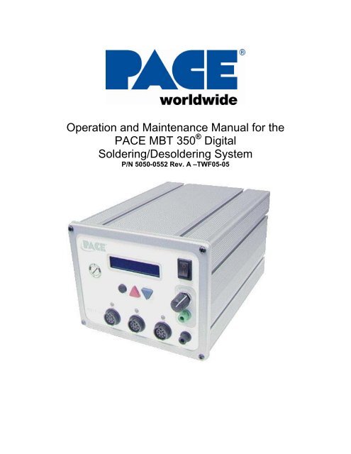
Operation and Maintenance <strong>Manual</strong> for the<br />
<strong>PACE</strong> <strong>MBT</strong> <strong>350</strong> ® Digital<br />
Soldering/Desoldering System<br />
P/N 5050-0552 Rev. A –TWF05-05
INDEX<br />
TITLE PAGE<br />
General Information<br />
Introduction.................................................................................3<br />
Specifications .............................................................................3<br />
EOS / ESD .................................................................................4<br />
Capabilities.................................................................................4<br />
<strong>MBT</strong> <strong>350</strong> Compatible Handpieces .............................................4<br />
Handpiece Tips ..........................................................................4<br />
Parts Identification................................................................................5<br />
Safety Guidelines.................................................................................7<br />
Safety ...................................................................................................8<br />
Usage Warnings/Cautions .........................................................8<br />
Servicing Precautions.................................................................9<br />
System Set-Up.....................................................................................9<br />
Attaching Tip & Tool Stand .......................................................11<br />
Instant Set Back Cubby.............................................................11<br />
Tip Removal ..............................................................................11<br />
Definitions ...........................................................................................11<br />
System Power Up ...............................................................................12<br />
LED Operation ....................................................................................13<br />
Operation ............................................................................................13<br />
Accessing Programming Menu .................................................16<br />
Password Menu.........................................................................13<br />
Setting Temperature C /F..........................................................13<br />
Set Upper Limit..........................................................................14<br />
Set Lower Limit..........................................................................14<br />
Setback Time ............................................................................14<br />
Set Auto Off...............................................................................14<br />
Scan Enable / Disable...............................................................14<br />
Set LCD Contrast ......................................................................15<br />
Set LED Backlite .......................................................................15<br />
Exiting the Programming Menu.................................................15<br />
Temperature Adjust Mode ..................................................................15<br />
Setting Channel Offset........................................................................15<br />
Accessing Calibration Menu ...............................................................15<br />
Hello Message ....................................................................................16<br />
Corrective Maintenance ......................................................................16<br />
Packing List.........................................................................................17<br />
Spare Parts .........................................................................................17<br />
Service ................................................................................................17<br />
LIMITED WARRANTY STATEMENT .................................................18<br />
Contact Information.............................................................................19<br />
©2012 <strong>PACE</strong> Inc., Southern Pines North Carolina. All Rights Reserved Page 2 of 19
General Information<br />
Introduction<br />
Thank you for purchasing the <strong>PACE</strong> model <strong>MBT</strong> <strong>350</strong> Soldering/Desoldering System. This manual will<br />
provide you with the information necessary to properly set up, operate and maintain the <strong>MBT</strong> <strong>350</strong>.<br />
Please read this manual thoroughly before using the unit. The <strong>MBT</strong> <strong>350</strong> system is designed for the<br />
most demanding soldering applications. The <strong>MBT</strong> <strong>350</strong> allows either SENSATEMP or TEMPWISE<br />
technology handpieces to be plugged into any of 3, continuously active, handpiece channels. The<br />
<strong>MBT</strong> <strong>350</strong> offers the benefits of SENSATEMP and TEMPWISE in a single system.<br />
<strong>PACE</strong>’s legendary SENSATEMP technology is renowned for its temperature stability and ability to<br />
handle high mass applications. For smaller components and when throughput is important, there is<br />
TEMPWISE. TEMPWISE is a patented technology that boasts the best response time for high<br />
volume applications and easily keeps up in a fast paced environment.<br />
The <strong>MBT</strong> <strong>350</strong> unit is available in either the 115 VAC or 230 VAC versions. The 230 VAC version<br />
system bears the CE Conformity Marking which assures the user that it conforms to all the<br />
requirements of (EU) directive EMC 89/336/EEC & 73/23/EEC.<br />
Specifications<br />
POWER REQUIREMENTS<br />
<strong>MBT</strong> <strong>350</strong> - Version operates on 97-127 VAC, 50/60 Hz.<br />
240 Watts, 2 Amp max, 100% Duty Cycle, Motor on.<br />
<strong>MBT</strong> <strong>350</strong>E - Version operates on 196-253 VAC, 50 Hz.<br />
240 Watts, 2 Amp max, 100% Duty Cycle, Motor on.<br />
PHYSICAL PARAMETERS<br />
Size: 13.5 cm H x 16.5 cm W x 26 cm D (5.3"H x 6.5"W x 10.25"D)<br />
Weight: 5 Kg. (11 Lbs.)<br />
VACUUM AND AIR Measurements at front panel AUTO SNAP-VAC and CONTROLLABLE<br />
PRESSURE Port.<br />
Vacuum Rise Time: Evacuates 200 ms Average as measured with <strong>PACE</strong> Process Monitor<br />
Vacuum: 26 in. Hg. (Nominal)<br />
Pressure: (4 P.S.I.) (Nominal MAXIMUM setting)<br />
Air Flow: 9 SLPM (0.32 SCFM) MAXIMUM<br />
TEMPERATURE SPECIFICATIONS<br />
Tip Temperature Range: 37-482 °C (100-900 °F) SensaTemp<br />
205-454 °C (400-850 °F) TempWise<br />
Nominal (see note).<br />
Digital Readout Resolution: ±1° (°C or °F)<br />
Tip Temperature Stability: ±1.1°C (2°F) at Idle from Set Tip Temperature.<br />
Temperature Accuracy: Meets or exceeds ANSI JSTD 001<br />
NOTE<br />
Actual minimum and maximum Operating Tip Temperatures may vary<br />
depending on handpiece & tip selection.<br />
©2012 <strong>PACE</strong> Inc., Southern Pines North Carolina. All Rights Reserved Page 3 of 19
EOS/ESD<br />
Tip-To-Ground Resistance: Less than 5 ohms.<br />
AC Leakage: Less than 2 millivolts RMS from 50Hz to 500Hz<br />
ENVIRONMENTAL REQUIREMENTS<br />
Ambient Operating Temperature: 0°C to 50°C (32°F to 120°F)<br />
Storage Temperature: -40°C to 100°C (-40°F to 212°F)<br />
Capabilities<br />
All capabilities are dependent upon the use of the appropriate Functional Accessories or Work Aids (refer<br />
to Basic Operation section). Available SensaTemp and TempWise handpieces and their associated<br />
assembly and repair functions are listed below. An Operations and Maintenance <strong>Manual</strong> is provided<br />
separately with each handpiece which describes the applications and recommended procedures for that<br />
particular tool.<br />
The <strong>MBT</strong> <strong>350</strong> allows either SENSATEMP or TEMPWISE technology handpieces to be plugged into any<br />
of 3, continuously active, handpiece channels. The new dual-purpose vacuum/pressure pump and<br />
delivery system with <strong>PACE</strong>’s patented SNAP-VAC Technology, provides the most vacuum available for<br />
desoldering applications. When used with an air pencil, the high resolution, pressure control valve allows<br />
for precise adjustment when working on the smallest components.<br />
<strong>MBT</strong> <strong>350</strong> Handpieces (Blue Connector)<br />
TD-100 handpiece - The most responsive soldering iron available. Uses tip-heater cartridges. TD-100 Kit<br />
P/N 6993-0263-P1 Handpiece only P/N 6010-0147-P1<br />
TD-100N handpiece – A nitrogen compatible version of the TD-100. Requires 6993-0271. TD-100N Kit<br />
P/N 6993-0272-P1 Handpiece only P/N 6010-0156-P1<br />
MT-100 handpiece – Tip heater cartridge tweezers for SMD removal. MT-100 Kit P/N 6993-0264-P1<br />
Handpiece only P/N 6010-0148-P1<br />
PS-90 Soldering Iron- Provides a wide range of SMD and thru-hole installation and removal capability as<br />
well as unsurpassed thermal performance on heavy, multilayer thru-hole assemblies at safe, lower<br />
working temperatures. A wide variety of 3/16" shank, quick change thru-hole and SMD tips (for chip<br />
components, SOTs, SOICs and other components) are available. PS-90 Kit P/N 6993-0267-P1<br />
Handpiece only P/N 6010-0150-P1<br />
PS-90N Soldering Iron- A nitrogen compatible version of the PS-90. Requires Nitrogen regulator kit P/N<br />
6993-0271. PS-90N Kit P/N 6993-0274-P1 Handpiece only P/N 6010-0157-P1<br />
SX-80 Sodr-X-Tractor handpiece - Air handpiece ideal for thru-hole desoldering on extra high mass<br />
multilayer boards. SX-80 Kit P/N 6993-0266-P1 Handpiece only P/N 6010-0149-P1<br />
TT-65 ThermoTweez handpiece - Performs removal of PLCC (J Leaded), LCCC (leadless) and other<br />
surface mount devices. TT-65 Kit P/N 6993-0268-P1 Handpiece only P/N 6010-0151-P1<br />
TJ-80 Mini Thermo Jet handpiece – Foot pedal activated precision air pencil for the installation or<br />
removal of SMDs. TJ-80 Kit P/N 6993-0271-P1 Handpiece only P/N 6010-0153-P1<br />
<strong>MBT</strong> <strong>350</strong> Handpieces tips<br />
A complete list of available handpiece tip is available from your local <strong>PACE</strong> distributor or online at<br />
www.paceworldwide.com.<br />
©2012 <strong>PACE</strong> Inc., Southern Pines North Carolina. All Rights Reserved Page 4 of 19
Parts Identification<br />
1<br />
2<br />
3<br />
4<br />
5<br />
Figure 1<br />
Listed below is a description of the Control Panel features. Use Figures 1 & 2 as a guide.<br />
1. LCD DISPLAY - Provides temperature information for all three channels. This includes: Operating Tip<br />
Temperature in Temperature Display Mode (normal operation), Tip Offset Constant in Tip Offset Mode,<br />
Set Tip Temperature in Tip Set Mode and other information in Calibration (CAL) Mode.<br />
2. PROGRAM KEY – Access tip offset feature and scroll through system channels.<br />
3. SCROLL UP KEY - Increases the Set Tip Temperature (in Tip Set Mode) and the Tip Offset Constant<br />
(in Tip Offset Mode) in one, then ten-degree increments. Also used in (Calibration) Mode.<br />
4. SCROLL DOWN KEY - Decreases the Set Tip Temperature (in Tip Set Mode) and the Tip Offset<br />
Constant (in Tip Offset Mode) in one then ten-degree increment. Also used in “CAL” (Calibration) Mode<br />
5. LED; CH 1, CH 2 or CH 3 Illuminated LED’s change color to reflect handpiece connectivity. GREEN<br />
(circuit complete) AMBER (in process) RED (no connection / error)<br />
6. POWER SWITCH - Turns system ON ("1") and OFF ("0"); controls input power to the system.<br />
7. PRESSURE ADJUSTMENT - Controls variable airflow pressure delivery.<br />
8. AUTO SNAP-VAC PORT - Quick connect fitting provides quick-rise vacuum for Sodr-X-Tractor,<br />
and ThermoPik handpieces. Vacuum is present when handpiece finger switch or optional foot pedal is<br />
actuated. Vacuum ceases 1.2 seconds after switch (or foot pedal) released.<br />
9. PRESSURE PORT – Quick connect fitting with provides airflow for Mini ThermoJet handpiece (in Hot<br />
Jet Mode) and Sodr-X-Tractor handpiece. Air pressure is present when handpiece finger switch or<br />
optional foot pedal is actuated. Air pressure ceases 1.2 seconds after switch (or foot pedal) is released<br />
10. CH 1 POWER RECEPTACLE - Provides power, tip ground, sensing circuitry and finger switch<br />
connection from <strong>MBT</strong> system to handpiece connected to Channel 1 (CH 1).<br />
CH 2 POWER RECEPTACLE - Provides power, tip ground, sensing circuitry and finger switch<br />
connection from <strong>MBT</strong> system to handpiece connected to Channel 2 (CH 2).<br />
CH 3 POWER RECEPTACLE - Provides power, tip ground, sensing circuitry and finger switch<br />
connection from <strong>MBT</strong> system to handpiece connected to Channel 3 (CH 3).<br />
©2012 <strong>PACE</strong> Inc., Southern Pines North Carolina. All Rights Reserved Page 5 of 19<br />
6<br />
7<br />
8<br />
9<br />
10
11<br />
12<br />
13<br />
14<br />
15<br />
Figure 2<br />
11. INSTANT-SETBACK CUBBY INPUT CHANNEL 1. Links handpiece on channel 1 to Instant-Setback<br />
Cubby. For use with TD-100 handpiece only.<br />
12. INSTANT-SETBACK CUBBY INPUT CHANNEL 2. Links handpiece on channel 2 to Instant-Setback<br />
Cubby. For use with TD-100 handpiece only.<br />
13. EARTH GROUND RECEPTACLE - Provides positive earth ground to which a ground cable can be<br />
connected from the work piece or work surface as part of a static control program.<br />
14. AC POWER RECEPTACLE / FUSE HOLDER - Receptacle for providing power to the system from<br />
AC outlet through power cord. Location of Fuse (F1), which protects system from over current conditions.<br />
15. FUSE - Provides overload protection for system.<br />
16. FOOT PEDAL RECEPTACLE - Input for Foot Pedal (optional), which activates vacuum or pressure<br />
to the air-operated handpieces.<br />
©2012 <strong>PACE</strong> Inc., Southern Pines North Carolina. All Rights Reserved Page 6 of 19<br />
16
If you require assistance in the use of this product, contact your local authorized <strong>PACE</strong> dealer or<br />
<strong>PACE</strong> directly as shown on page 15 of this manual<br />
Safety Guidelines<br />
The following are safety precautions that personnel must understand and follow when using or servicing this<br />
product.<br />
1. POTENTIAL SHOCK HAZARD - Repair procedures on <strong>PACE</strong> products should be performed by Qualified<br />
Service Personnel only. Line voltage parts may be exposed when the equipment is disassembled.<br />
Service personnel must avoid contact with these parts when troubleshooting the product.<br />
2. To prevent personnel injury, adhere to safety guidelines in accordance with OSHA and other<br />
applicable safety standards.<br />
3. Handpiece heaters and installed tips are hot when the handpiece is powered on and for a period of<br />
time after power off. DO NOT touch either the heater or the tip. Severe burns may result.<br />
4. <strong>PACE</strong> Tip & Tool Stands and handpiece cubbies are designed specifically for use with the<br />
associated handpiece and houses it in a manner that protects the user from accidental burns.<br />
Always store the handpiece in its holder. Be sure to place the handpiece in its holder after use and<br />
allow to cool before storing.<br />
5. Always use <strong>PACE</strong> systems in a well ventilated area. A fume extraction system such as those<br />
available from <strong>PACE</strong> are highly, recommended to help protect personnel from solder flux<br />
fumes.<br />
6. Exercise proper precautions when using chemicals (e.g., solder paste).Refer to the Material<br />
Safety Data Sheet (MSDS) supplied with each chemical and adhere to all safety precautions<br />
recommended by the manufacturer.<br />
©2012 <strong>PACE</strong> Inc., Southern Pines North Carolina. All Rights Reserved Page 7 of 19
Safety<br />
<strong>PACE</strong> adheres to the following Heading Guidelines (based on OSHA guidelines) when listing special<br />
information or precautions to be taken. Especially important are all procedures and practices which, if not<br />
strictly observed, could result in injury or loss of life. These "NOTES", "CAUTIONS","WARNINGS" and<br />
"DANGERS" are inserted in this manual whenever deemed necessary. They appear in a blocked off form<br />
with double outline and a shaded background to highlight the information as shown below.<br />
“NOTE”<br />
Used to indicate a statement of company recommendation or policy. The message may relate<br />
directly or indirectly to the safety of personnel or protection of property. NOTE is not associated<br />
directly with a hazard or hazardous situation and is not used in place of "CAUTION", "WARNING"<br />
or "DANGER".<br />
“CAUTION”<br />
Used to indicate a hazardous situation, which may result in minor or moderate injury. May also be<br />
used to alert personnel to conditions, procedures and practices which, if not observed, could<br />
result in damage to or destruction of the product or other equipment.<br />
“WARNING”<br />
Used to define additional information that if not closely followed might result in serious damage to<br />
equipment and represent a potential for serious personnel injury.<br />
“DANGER”<br />
Defines additional information that if not closely followed might result in severe personnel injury or<br />
death. Danger is not used for property damage unless personal injury risk is present.<br />
Usage Warnings/Cautions<br />
WARNINGS<br />
NOTE<br />
1. A fire hazard may arise if the <strong>MBT</strong> <strong>350</strong> is used improperly.<br />
2. Do not use the <strong>MBT</strong> <strong>350</strong> in the presence of an explosive atmosphere.<br />
3. Be careful when using the <strong>MBT</strong> <strong>350</strong> in places where there are combustible materials.<br />
Heat may be conducted to combustible materials, which are out of sight.<br />
4. Do not apply heat from the <strong>MBT</strong> <strong>350</strong> to one place for a long time.<br />
5. Do not leave the <strong>MBT</strong> <strong>350</strong> unattended while powered on.<br />
©2012 <strong>PACE</strong> Inc., Southern Pines North Carolina. All Rights Reserved Page 8 of 19
CAUTIONS<br />
1. Utilize all standard electrical safety precautions when using this or any other electrical<br />
equipment.<br />
2. Always use this system in a well-ventilated area. A fume extraction system such as those<br />
available from <strong>PACE</strong> are highly recommended to protect personnel from solder flux<br />
fumes.<br />
5. Exercise proper precautions when using chemicals (e.g., solder paste). Refer to the<br />
Material Safety Data Sheet (MSDS) supplied with each chemical and adhere to all safety<br />
precautions recommended by the manufacturer.<br />
Servicing Precautions<br />
DANGERS<br />
POTENTIAL SHOCK HAZARD - Repair procedures performed on this product should be<br />
performed by qualified service personnel only. Line voltage parts will be exposed when<br />
equipment is disassembled. Service personnel must avoid contact with these parts when<br />
troubleshooting.<br />
Precautions<br />
The following are general safety precautions that personnel must understand and follow when<br />
using or servicing this product. These precautions may or may not be included elsewhere in this<br />
manual.<br />
Safety<br />
System Set-Up<br />
Power Source<br />
Electrical Requirements<br />
The <strong>MBT</strong> <strong>350</strong> unit draws approximately 240 VA (240Watts), which is listed on the nameplate<br />
on the power source rear panel. A separate, dedicated AC supply line circuit may be required<br />
to adequately power the unit/system. If your power outlet cannot provide suitable power,<br />
arrange for a qualified, licensed electrician to install one for you.<br />
Set up the <strong>MBT</strong> <strong>350</strong> system using the following steps and associated drawings.<br />
1. Remove the <strong>MBT</strong> <strong>350</strong> from its shipping container(s). Store the shipping container(s) in a<br />
convenient location. Reuse of these containers will prevent damage if you ship or store<br />
the system.<br />
2. Set the <strong>MBT</strong> <strong>350</strong> unit on a convenient workbench.<br />
3. Place the POWER Switch (on power source front panel) in the "OFF"<br />
or "0" position.<br />
©2012 <strong>PACE</strong> Inc., Southern Pines North Carolina. All Rights Reserved Page 9 of 19
4. Inspect all system components, check for shipping damage, and ensure that all<br />
purchased components (standard and options) are present. Use the drawings provided<br />
in the following pages as a guide for checking the parts that come with the unit.<br />
5. Assemble Tip & Tool Stands. Attach to the power source if desired. Assembly<br />
instructions are enclosed with each Tip & Tool Stand.<br />
6. Connect blue handpiece connector plug(s) to<br />
the blue power receptacle(s) CH 1, CH 2<br />
and/or CH 3 in the following manner. See Fig.<br />
3a.<br />
a) With the Connector Key end facing the<br />
power source, turn the Locking Ring fully<br />
counterclockwise.<br />
b) Orient guide on connector with slot of<br />
power receptacle.<br />
c) Insert connector into power receptacle.<br />
d) Turn Locking Ring fully clockwise to lock<br />
in place.<br />
7. To avoid confusion among handpieces, <strong>PACE</strong><br />
recommends the use of colored cable markers<br />
Figure 3a<br />
(P/N 6993-0136 Cable Marker Kit) to identify<br />
the particular handpiece. Attach any two like<br />
colored markers, one to each end of the<br />
handpiece power cable or air hose. Select and<br />
use a different colored marker for each<br />
handpiece. Labels are also provided to mark<br />
Tip & Tool Stands with the name of the<br />
associated handpiece.<br />
8. If you have purchased an optional foot pedal,<br />
insert the connector plug into the PEDAL<br />
Receptacle on the rear panel of the power<br />
source. See Fig. 3b. Install additional<br />
handpieces and accessories as necessary.<br />
9. Plug the prong end of the power cord into a<br />
convenient three wire grounded AC power<br />
Figure 3b<br />
outlet. The system is now ready for operation.<br />
10. Read the "OPERATION" section of this manual thoroughly before operating the system.<br />
©2012 <strong>PACE</strong> Inc., Southern Pines North Carolina. All Rights Reserved Page 10 of 19
Attaching Tip & Tool Stand to <strong>MBT</strong> <strong>350</strong><br />
Attach the stand to the power source, using the following procedure. Refer to illustration.<br />
1. Insert the 2 enclosed hex head Mounting Screws into the slot on the side of the Power Source. Some<br />
kits may contain 4 mounting screws; 2 with small heads and 2 with large heads. Use the 2 screws that fit<br />
properly in the slot. Also, some Power Source cases have more than 1 slot; use the lower slot.<br />
2. Position the Mounting Screws to the rear of the power source and<br />
spaced approximately 2 inches apart. Refer to illustration.<br />
3. Place the Tip & Tool Stand beside the power source. Insert ends<br />
of the 2 Mounting Screws into the 2 adjacent Tip & Tool<br />
Stand mounting holes.<br />
4. Install a Thumb Nut onto the end of each Mounting Screw. Tighten<br />
Thumb Nuts to secure the Tip & Tool Stand in position.<br />
You may wish to set the Power Source on its side and remove the<br />
drip tray to ease installation of the Thumb Nut.<br />
5. Additional Tip & Tool Stands or “cubby’s” may be secured to each<br />
other by aligning mounting holes on stand sides. Use hex head<br />
screws and thumb nuts to mount cubbys together.<br />
Optional Instant-Setback Cubby<br />
Figure 4<br />
The optional Instant SetBack Cubby is available for use with the <strong>MBT</strong> <strong>350</strong> and will only function with the<br />
TD-100 handpiece. When connected, it automatically puts the system into Setback mode when the TD-<br />
100 is placed in the cubby. The Instant Setback Cubby will only function with the TD-100 Handpiece. The<br />
<strong>MBT</strong> <strong>350</strong> is capable of using two Instant Setback Cubbys at the same time. The instant SetBack<br />
receptacles are located on the back panel. See figure 3. The instant setback cubby's function is to protect<br />
tips, not power off the system. Instant setback is a feature that lowers the temperature to <strong>350</strong>°F after 45<br />
seconds of inactivity. At <strong>350</strong>°F the solder has solidified so any iron erosion on the tips ceases, protecting<br />
the tip.<br />
Tip Removal<br />
WARNING<br />
Never remove a heated tip using bare hands. Use the Hot Grip Rubber Pad or Tip Tool.<br />
Never use a wrench or pliers when removing a handpiece tips.<br />
©2012 <strong>PACE</strong> Inc., Southern Pines North Carolina. All Rights Reserved Page 11 of 19
WARNING:<br />
1. Remove TD-100 and MT-100 handpieces while holding Tip Heater Cartridge with the Rubber<br />
Pad; gently pull the THC from handpiece. For PS-90, SX-80, TT-65, and TJ-80 handpieces,<br />
loosen heater set screw and remove iron tip with Rubber Pad.<br />
2. Place the tip (still hot) in tip / tool stand.<br />
Definitions<br />
Please read and become familiar with the definitions of each of the following terms that are used<br />
repeatedly in the following operational procedures.<br />
Auto-Off: Safety feature that turns power off (1-90 minutes, settable in 1 minute increments) after the<br />
system has entered Temperature Setback.<br />
Normal Operation: Normal operating mode of the system in which the Operating Tip<br />
Temperature is displayed.<br />
Password: The Password feature of the <strong>MBT</strong> <strong>350</strong> system will prevent unauthorized alteration of<br />
stored system temperature parameters and feature settings. If a Password has been installed,<br />
the LED Display will display an instruction to enter the password. Enter a four digit number selected<br />
using the scroll up /down keys on the system front panel) when a setting change is attempted.<br />
Programming Menu: The interface used to program the system features parameters (e.g.,<br />
temperature limits, password, setback time).<br />
Set Tip Temperature: The operator selected idle tip temperature entered into the system memory.<br />
Temperature Adjust Mode: Mode of operation where the Set Tip Temperature may be adjusted.<br />
Temperature Setback: System feature that will independently set back the Set Tip Temperature to<br />
177°C (<strong>350</strong>°F) after a user selected or preset period of handpiece inactivity.<br />
System Power Up<br />
1. Insert the female end of the power cord into the AC Power Receptacle on the rear panel of<br />
the power source.<br />
2. Plug the prong end (male end) of the power cord into an appropriate 3 wire grounded AC<br />
supply receptacle.<br />
CAUTION<br />
To insure operator and ESD/EOS safety, the AC power supply receptacle must be checked for<br />
proper grounding before initial operation.<br />
©2012 <strong>PACE</strong> Inc., Southern Pines North Carolina. All Rights Reserved Page 12 of 19
LED Operation<br />
The Green colored Temperature LED on the power source front panel indicates System Status.<br />
Operation<br />
LED Green - Indicates that the set tip temperature has been reached. Power to the handpiece is<br />
cycling Off and On to maintain set temperature.<br />
LED Amber - Continuous power is being delivered to the handpiece. This condition is evident<br />
when the system is first powered up (handpiece heater cold) or the Variable Temperature Control<br />
setting is increased.<br />
LED Red - No power is being delivered to the handpiece heater. If the LED never illuminates,<br />
check for a faulty handpiece heater (see Corrective Maintenance section).<br />
Accessing Programming Menu<br />
The menu driven LED Display of the <strong>MBT</strong> <strong>350</strong> system allows you to easily customize your system. By<br />
accessing the programming menu, you can:<br />
• Enter, remove or change a Password.<br />
• Set the Default Temperature scale to °F or °C as desired.<br />
• Change the Upper and Lower Temperature limits.<br />
• Enable or disable the Temperature Setback feature.<br />
• Enable or disable the Auto Off feature.<br />
• Enable or disable the Scan feature.<br />
• Enable or disable the display contrast and backlight settings.<br />
To access set up mode, press and hold the PROGRAM Key while powering on unit. Release key<br />
when “Software Version” appears. Pressing the PROGRAM Key will scroll through each menu<br />
option without changing the stored setting.<br />
Follow the <strong>MBT</strong> <strong>350</strong>’s on screen prompts to review or set each menu option starting with the<br />
password feature.<br />
1. Password Menu<br />
Same Retains previous password and move to the next step.<br />
Yes Prompts the operator to enter a new password. Use the scroll up / down keys on the<br />
system front panel to select a four digit password. Once password is entered, press the<br />
PROGRAM Key to accept the password and move to the next step. Entering “0000” as<br />
a password will disable the password feature.<br />
No Selecting “NO” bypasses the password feature and moves to the next step.<br />
2. Setting Temperature C /F<br />
The LED Display now shows the stored default Temperature Scale °C or °F temperature shown on<br />
LED Display). Choose one of the following:<br />
a) Press the PROGRAM Key to keep the stored default Temperature Scale.<br />
b) Press and release the UP Key to change the default Temperature Scale.<br />
Press and release the PROGRAM Key to move to the next step.<br />
©2012 <strong>PACE</strong> Inc., Southern Pines North Carolina. All Rights Reserved Page 13 of 19
3. Set Upper Limit<br />
Press the UP and DOWN to set the upper temperature limit. 900°F is the upper limit for<br />
SensaTemp handpieces. The Upper limit for TempWise handpieces is 850°F. Press and release the<br />
PROGRAM Key to move to the next step. The upper limit feature will limit the temperature range<br />
that an operator may work within. Setting a password will lock out unwanted changes to this feature.<br />
4. Set Low Limit<br />
Press the UP and DOWN to set the upper temperature limit. 100°F is the upper limit for<br />
SensaTemp handpieces. The Upper limit for TempWise handpieces is 400°F. Press and release the<br />
PROGRAM Key to move to the next step. The lower limit feature will limit the temperature range<br />
that an operator may work within. Setting a password will lock out unwanted changes to this feature.<br />
Adjusting the working temperature below the set lower limit will turn power off to the selected channel.<br />
5. SetBack Time<br />
Choose one of the following:<br />
a) Press and release the PROGRAM Key to keep the currently stored Temperature Setback<br />
time.<br />
b) Press and release the Scroll UP Key to enable or increase the stored Temperature Setback<br />
time. Press and release the PROGRAM Key to proceed to the next step. Set back may be<br />
disabled by entering (00). The maximum set back time is 90 minutes.<br />
c) Press and release the Scroll Down Key to decrease or enter “00” to disable the stored<br />
Temperature Setback time. Press and release the PROGRAM Key to proceed to the next<br />
step.<br />
The LED Display now shows the stored Temperature Setback time in minutes<br />
6. Set Auto Off<br />
Press the UP Key to enter increase the auto-off time. When enabled, the Auto Off safety system of<br />
the <strong>MBT</strong> <strong>350</strong> system turns off the power to the Handpiece 10- 90 minutes after entering Temperature<br />
Setback. When the system has entered Temperature Setback, an Auto Off timer within the system<br />
circuitry will start running if Auto Off is turned on. When Auto Off has activated, the LED Display will<br />
blink “OFF”. To disable the Auto-Off feature, enter “00”. If any key is pressed during the selected time<br />
out period, the Auto Off timer is reset. The system will return to normal operation. At the end of the<br />
time out period, the system will enter Auto Off. Power is turned off to the heater and the LED Display<br />
will show a flashing “OFF ” and the LED indicator will turn red. Press and release the PROGRAM Key<br />
to move to the next step.<br />
7. Scan Enable / Disable<br />
Press and release the Scroll UP Key to enable or disable the scan mode feature. When enabled<br />
the scan feature of the <strong>MBT</strong> <strong>350</strong> scans each channel and display it’s information individually for 3<br />
seconds than continually repeats the order. Press and release the PROGRAM Key to move to the<br />
next step.<br />
©2012 <strong>PACE</strong> Inc., Southern Pines North Carolina. All Rights Reserved Page 14 of 19
8. Set LCD Contrast<br />
Press the UP and DOWN to enter increase or decrease LCD contrast. The range of contrast is<br />
1 to 100. Press and release the PROGRAM Key to move to the next step.<br />
9. Set LED Backlite<br />
Press the UP and DOWN to enter increase or decrease LCD contrast. The range of backlite is<br />
1 to 100. Press and release the PROGRAM Key to move to the next step.<br />
7. Exiting the Programming Menu<br />
The LED Display now reads "End". The Set-Up Mode procedure is now complete. Choose one of the<br />
following steps:<br />
a) Press and release the UP Key to exit Set-Up Mode and return to normal operation.<br />
b) Press and release the DOWN Key to return to the start of the Set-Up Mode procedure.<br />
Temperature Adjust Mode<br />
To increase of decrease handpiece temperature, press the UP or DOWN arrow key once. The<br />
display will show the current temperature setting for channel “1”. Press the UP or DOWN arrow<br />
keys to increase of decrease handpiece temperature for channel “1”. Or press the PROGRAM Key<br />
to move the next channel. After a period of 10 seconds of inactivity, the display will return to normal<br />
operation.<br />
Setting Channel Offset<br />
To increase of decrease handpiece temperature offset, press the PROGRAM Key once. The display<br />
will show the current temperature offset setting for channel “1”. Press the UP or DOWN arrow keys<br />
to increase of decrease offset temperature for channel “1”. Or press the PROGRAM Key to move the<br />
next channel. After a period of 10 seconds of inactivity, the display will return to normal operation.<br />
Accessing Calibration Menu<br />
Press and hold the PROGRAM Key and the UP keys while powering on unit. Release keys<br />
when “Software Version” appears. Follow the instructional prompts to review or set each menu<br />
option.<br />
Calibration Instructions<br />
The steps for the procedure are:<br />
1. Remove any offset from the system by disconnecting the handpiece from the system. Reconnecting<br />
the handpiece and proceed to step 2.<br />
2. LED should go to amber. Set the <strong>MBT</strong> <strong>350</strong>°F to (700°C).<br />
3. Record the actual temperature of the tip from your temperature verification device.<br />
4. Place the <strong>MBT</strong> <strong>350</strong> into the Calibration mode. Start with the system power switch in the off<br />
position. Press and hold the PROGRAM Key and the UP key while turning the<br />
system on. Release both keys when the display reads version E.9 or higher.<br />
5. The display will now read Channel “1” System Cal? Press the UP key to enter a temperature<br />
for channel “1”. Press key / NO to move to the next channel.<br />
6. Use the UP and DOWN keys to enter the temperature that you recorded by the temperature<br />
verification device. For example, your temperature verification device reads 695 °F. Scroll through<br />
until the display reads 695.<br />
7. Press the PROGRAM Key to save calibration and move to the next channel. Upon exiting,<br />
LED will illuminate green and the display will return to normal operation mode.<br />
©2012 <strong>PACE</strong> Inc., Southern Pines North Carolina. All Rights Reserved Page 15 of 19
Hello Message<br />
The Hello Message feature of the <strong>MBT</strong> <strong>350</strong> allows the operator to enter a message that will be<br />
displayed when the system is turned on. To access the Hello Message menu, press and hold the<br />
PROGRAM Key and DOWN arrow keys while powering on unit. Release keys when “Software<br />
Version” appears. The <strong>MBT</strong> <strong>350</strong> will display “ Do you want to input a Hello Message? Using the UP<br />
key, scroll through the characters pausing on your selection. Press the PROGRAM Key once to<br />
move the cursor to the next character. Press the setup key twice to exit the Hello Message menu.<br />
If a hello message has been entered, the display will prompt the user to delete the hello message.<br />
Press the UP key to change the hello message or press the DOWN arrow key to exit and return<br />
the normal operation mode.<br />
Corrective Maintenance<br />
Power Source<br />
Refer to the table below. Most malfunctions are simple and easy to correct.<br />
Symptom Probable Cause Solution<br />
No power to system<br />
Blown Fuse Inspect and replace the fuse(s) located on the power source<br />
rear panel<br />
Line cord unplugged Plug line cord into the appropriate AC outlet<br />
Heater Assembly does not<br />
heat<br />
Open Heater Contact <strong>PACE</strong> for assistance<br />
Little or no air flow, heater<br />
heats and blower is running<br />
Kinked air hose<br />
Change routing of air hose to remove<br />
kinks<br />
Little or no vacuum Worn vacuum pump Replace vacuum pump. Contact <strong>PACE</strong> for assistance.<br />
Vacuum Cup will not hold Worn or broken Replace vacuum cup<br />
component<br />
vacuum cup<br />
Vacuum Pickup Rod binding<br />
Vacuum Pickup rod is<br />
bent<br />
NOTE<br />
Before calibration is attempted, the system should be allowed to reach set temperature and<br />
stabilize for at least 15 seconds before calibrating.<br />
Contact <strong>PACE</strong> for assistance<br />
©2012 <strong>PACE</strong> Inc., Southern Pines North Carolina. All Rights Reserved Page 16 of 19
Packing List<br />
Item # Description Part Number <strong>MBT</strong> <strong>350</strong> <strong>MBT</strong> <strong>350</strong> E <strong>MBT</strong> <strong>350</strong> <strong>MBT</strong> <strong>350</strong> E<br />
Only Only System System<br />
1 System Power Supply 8007-0452 1 0 1 0<br />
2 System Power Supply (Export) 8007-0453 0 1 0 1<br />
3 Power Cord, 115V 1332-0094-P1 1 0 1 0<br />
4 Power Cord, 230V 1332-0093-P1 0 1 0 1<br />
5 Hot Grip Removal Pad 1100-0307-P1 0 0 1 1<br />
6 Fiber Cleaning Tool 1100-0232 0 0 1 1<br />
7 Cleaning Sponge Tool 1100-0233 0 0 1 1<br />
8 Wire Brush 3/16 Diameter 1127-0014 0 0 1 1<br />
9 Cable Marker Kit 6993-0136-P1 0 0 1 1<br />
10 Angle Bracket Kit 6018-0097-P1 0 0 1 1<br />
11 <strong>PACE</strong> Screwdriver 1100-0230 0 0 1 1<br />
12 SX-80 (Blue Connector) Kit 6993-0266-P1 0 0 1 1<br />
13 MT-100 ((Blue Connector) Kit 6993-0264-P1 0 0 1 1<br />
14 TD-100 (Blue Connector) Kit 6993-0264-P1 0 0 1 1<br />
15 Operations <strong>Manual</strong> CD 5050-0459 0 0 1 1<br />
Spare Parts<br />
Service<br />
Item # Description <strong>PACE</strong> Part Number<br />
1 Fuse, 2.0 A, 125 V, Lag Time (<strong>MBT</strong> <strong>350</strong>) 1159-0247<br />
2 Fuse, 1.25 A, 230 V, Lag Time (<strong>MBT</strong> <strong>350</strong>E) 1159-0217<br />
Please contact <strong>PACE</strong> or your local distributor for service and repair.<br />
©2012 <strong>PACE</strong> Inc., Southern Pines North Carolina. All Rights Reserved Page 17 of 19
<strong>PACE</strong> WORLDWIDE LIMITED WARRANTY<br />
<strong>PACE</strong> warrants to the first user that products manufactured by it and supplied hereunder are free of<br />
defects in materials and workmanship for a period of one (1) year from the date of receipt by such user.<br />
This Warranty as applied to blowers and motor pumps is limited to a period of one (1) year. Monitors,<br />
computers and other brand equipment supplied but not manufactured by <strong>PACE</strong> are covered under their<br />
respective manufacturer’s warranty in lieu of this Warranty.<br />
This warranty does not cover wear and tear under normal use, repair or replacement required as a result<br />
of misuse, improper application, mishandling or improper storage. Consumable items such as tips,<br />
heaters, filters, etc. which wear out under normal use are excluded. Failure to perform recommended<br />
routine maintenance, alterations or repairs made other than in accordance with <strong>PACE</strong>’s directions, or<br />
removal or alteration of identification markings in any way will void this warranty. This warranty is<br />
available only to the first user, but the exclusions and limitations herein apply to all persons and entities.<br />
<strong>PACE</strong> MAKES NO OTHER WARRANTY, EXPRESS OR IMPLIED, AND MAKES NO WARRANTY OF<br />
MERCHANTABILITY OR FITNESS FOR A PARTICULAR PURPOSE.<br />
<strong>PACE</strong> will, at its option, repair or replace any defective products at its facility or other location approved<br />
by it at no charge to user, or provide parts without charge for installation by the user in the field at user’s<br />
expense and risk. User will be responsible for all costs of shipping equipment to <strong>PACE</strong> or other location<br />
for warranty service.<br />
EXCEPT FOR THE REMEDY ABOVE DESCRIBED, UNLESS OTHERWISE REQUIRED BY<br />
APPLICABLE LAW, <strong>PACE</strong> WILL HAVE NO OTHER OBLIGATION WITH REGARD TO ANY BREACH<br />
OF WARRANTY OR OTHER CLAIM WITH RESPECT TO THE PRODUCTS, OR LIABILITY FOR ANY<br />
DIRECT, INDIRECT, CONSEQUENTIAL, OR INCIDENTAL LOSS OR DAMAGE CAUSED BY OR<br />
OCCURRING IN CONNECTION WITH ANY OF THE PRODUCTS.<br />
Warranty service may be obtained by contacting the appropriate <strong>PACE</strong> Company or local Authorized<br />
<strong>PACE</strong> distributor as set forth below to determine if return of any item is required, or if repairs can be made<br />
by the user in the field.<br />
Defective products may not be returned to <strong>PACE</strong> without a Service Authorization (“SA”) Number.<br />
Any warranty or other claim with respect to the products must be made in writing delivered to <strong>PACE</strong> (or<br />
local Authorized <strong>PACE</strong> distributor for Buyers outside the USA and the United Kingdom) within a<br />
reasonable time of the expiration date of this warranty with sufficient evidence of purchase and date of<br />
receipt, otherwise user’s rights under this warranty shall be deemed waived.<br />
<strong>PACE</strong> Incorporated retains the right to make changes to specifications contained herein at any time,<br />
without notice. Contact your local authorized <strong>PACE</strong> Distributor or <strong>PACE</strong> Incorporated to obtain the latest<br />
specifications.<br />
The following are trademarks and/or service marks of <strong>PACE</strong>, Incorporated, MD, USA:<br />
INSTACAL , FUMEFLO , HEATWISE , <strong>PACE</strong>WORLDWIDE , PERMAGROUND ,<br />
POWERPORT , POWERMODULE , TEMPWISE , TIP-BRITE , AUTO-OFF , and<br />
TEKLINK .<br />
The following are registered trademarks and/or service marks of <strong>PACE</strong> Incorporated, Annapolis Junction<br />
Maryland U.S.A.<br />
ARM-EVAC ® , FLO-D-SODR ® , MINIWAVE ® , <strong>PACE</strong> ® , SENSATEMP ® , SNAP-VAC ® ,<br />
SODRTEK ® , SODR-X-TRACTOR ® , THERMOFLO ® , THERMOJET ® , THERMOTWEEZ ® ,<br />
VISIFILTER ® , THERMO-DRIVE ® , and TOOLNET ® .<br />
©2012 <strong>PACE</strong> Inc., Southern Pines North Carolina. All Rights Reserved Page 18 of 19
<strong>PACE</strong> products meet or exceed all applicable military and civilian EOS/ESD, temperature stability and<br />
other specifications including MIL STD 2000, ANSI/JSTD 001, IPC7711, and IPC A-610.<br />
www.paceworldwide.com<br />
<strong>PACE</strong> Incorporated Pace Europe<br />
255 Air Tool Drive 11 Holdom Avenue<br />
Southern Pines, Bletchley, Milton Keynes,<br />
North Carolina, 28387 United Kingdom, MK1 1QU<br />
Tel: (877) 882-<strong>PACE</strong> Tel: 011 44 1908 277666<br />
Tel: (910) 695-7223 Fax: 011 44 1908 277777<br />
Fax: (910) 695-1594<br />
©2012 <strong>PACE</strong> Inc., Southern Pines North Carolina. All Rights Reserved Page 19 of 19