
You also want an ePaper? Increase the reach of your titles
YUMPU automatically turns print PDFs into web optimized ePapers that Google loves.
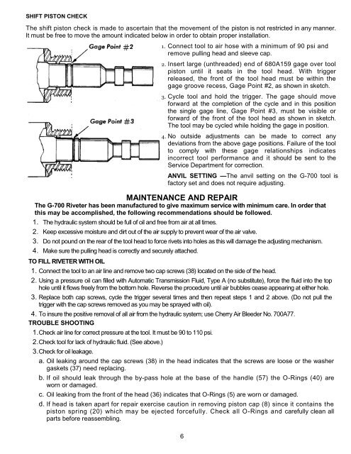
SHIFT PISTON CHECK<br />
The shift piston check is made to ascertain that the movement of the piston is not restricted in any manner.<br />
It must be free to move the amount indicated below in order to obtain proper installation.<br />
1. Connect tool to air hose with a minimum of 90 psi and<br />
remove pulling head and sleeve cap.<br />
2. Insert large (unthreaded) end of 680A159 gage over tool<br />
piston until it seats in the tool head. With trigger<br />
released, the front of the tool head must be within the<br />
gage groove recess, Gage Point #2, as shown in sketch.<br />
3. Cycle tool and hold the trigger. The gage should move<br />
forward at the completion of the cycle and in this position<br />
the single gage line, Gage Point #3, must be visible or<br />
forward of the front of the tool head as shown in sketch.<br />
The tool may be cycled while holding the gage in position.<br />
4. No outside adjustments can be made to correct any<br />
deviations from the above gage positions. Failure of the tool<br />
to comply with these gage relationships indicates<br />
incorrect tool performance and it should be sent to the<br />
Service Department for correction.<br />
ANVIL SETTING —The anvil setting on the G-700 tool is<br />
factory set and does not require adjusting.<br />
MAINTENANCE AND REPAIR<br />
The G-700 <strong>Rivet</strong>er has been manufactured to give maximum service with minimum care. In order that<br />
this may be accomplished, the following recommendations should be followed.<br />
1. The hydraulic system should be full of oil and free from air at all times.<br />
2. Keep excessive moisture and dirt out of the air supply to prevent wear of the air valve.<br />
3. Do not pound on the rear of the tool head to force rivets into holes as this will damage the adjusting mechanism.<br />
4. Make sure the pulling head is correctly and securely attached.<br />
TO FILL RIVETER WITH OIL<br />
1. Connect the tool to an air line and remove two cap screws (38) located on the side of the head.<br />
2. Using a pressure oil can filled with Automatic Transmission Fluid, Type A (no substitute), force the fluid into the top<br />
hole until it flows freely from the bottom hole. Reverse the procedure until air bubbles cease appearing at either hole.<br />
3. Replace both cap screws, cycle the trigger several times and then repeat steps 1 and 2 above. (Do not pull the<br />
trigger with the cap screws removed as you may be sprayed with oil).<br />
4. To insure the positive removal of all air from the hydraulic system; use Cherry Air Bleeder No. 700A77.<br />
TROUBLE SHOOTING<br />
1.Check air line for correct pressure at the tool. It must be 90 to 110 psi.<br />
2.Check tool for lack of hydraulic fluid. (See above.)<br />
3.Check for oil leakage.<br />
a. Oil leaking around the cap screws (38) in the head indicates that the screws are loose or the washer<br />
gaskets (37) need replacing.<br />
b. If oil should leak through the by-pass hole at the base of the handle (57) the O-Rings (40) are<br />
worn or damaged.<br />
c. Oil leaking from the front of the head (36) indicates that O-Rings (5) are worn or damaged.<br />
d. If head is taken apart for repair exercise caution in removing piston cap (8) since it contains the<br />
piston spring (20) which may be ejected forcefully. Check all O-Rings and carefully clean all<br />
parts before reassembling.<br />
6