ORIGINAL INSTRUCTIONS HAND HYDRAULIC RIVETER NSN ...
ORIGINAL INSTRUCTIONS HAND HYDRAULIC RIVETER NSN ...
ORIGINAL INSTRUCTIONS HAND HYDRAULIC RIVETER NSN ...

You also want an ePaper? Increase the reach of your titles
YUMPU automatically turns print PDFs into web optimized ePapers that Google loves.
<strong>ORIGINAL</strong> <strong>INSTRUCTIONS</strong><br />
Patent Number 5425164<br />
1<br />
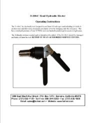
<strong>HAND</strong> <strong>HYDRAULIC</strong> <strong>RIVETER</strong><br />
<strong>NSN</strong> 5120-01-432-9361<br />
1224 East Warner Ave,<br />
Santa Ana, CA 92705<br />
Tel: 1-714-545-5511<br />
Fax: 1-714-850-6093<br />
www.cherryaerospace.com
Description<br />
The Cherry G750A hand hydraulic riveting tool provides<br />
the versatility of a pneumatic-hydraulic riveter but with the<br />
lightweight, high pull strength ratio not found in other<br />
hand riveters.<br />
It has a unique 2-stage hydraulic power cylinder that<br />
provides the user with the ease of pulling the handle<br />
without the strain normally endured to install a high<br />
strength fastener. This patented 2-stage power feature<br />
allows the user to squeeze the handle throughout the<br />
increase power requirement, without feeling the need<br />
to squeeze harder to install the fastener.<br />
The Cherry G750A hand riveter can install a variety of<br />
blind fastener styles, diameters, head configurations,<br />
and material combinations without changing the pulling<br />
head or adjusting the tool. With the standard pulling head<br />
it can install CherryMAX ® and SST ® blind rivets in -4, -5,<br />
-6, diameters. It is also capable of installing -8 dia<br />
CherryMAX ® , -04, -05, -06 dia. MaxiBolt blind bolts or<br />
threaded inserts by simply changing the pulling head.<br />
Specifications<br />
Weight 1.9 lbs.<br />
Stroke .750"<br />
Pulling Capacity 3800/4400 lbs.<br />
Overall Height 6.4"<br />
Overall Length 7.5"<br />
Fluid used<br />
Use automatic transmission fluid Type “A” (no substitutes). CHERRY® recommends using ATF, Dexron III oil.<br />
FIRST AID<br />
PROPERTIES<br />
Specific gravity 0.863<br />
Weight per gallon 7.18 lbs.<br />
Open flash point >200°C (392°F)<br />
DEXRON III OIL SAFETY DATA<br />
Skin: Wash thoroughly with soap and water as soon as possible. Casual contact requires no immediate attention.<br />
If irritation develops, consult a physician.<br />
Ingestion: Seek medical attention immediately. DO NOT INDUCE VOMITING.<br />
Eyes: Flush with copious amounts of water. If irritation develops, consult a physician.<br />
Inhalation: No significant adverse health effects are expected to occur on short term exposure. Remove from contaminated area.<br />
Apply artificial respiration if needed. If unconscious, consult physician.<br />
FIRE: Suitable extinguishing media: CO2, dry powder, foam or water fog. DO NOT use water jets.<br />
ENVIRONMENT: Waste Disposal: In accordance with local, state and federal regulations.<br />
Spillage: Prevent entry into drains, sewers and water courses. Soak up with diatomaceous earth or other inert material.<br />
Store the spent fluid in appropriate containers for disposal.<br />
<strong>HAND</strong>LING: Eye protection required. Protective gloves recommended. Chemically resistant boots and apron recommended. Use in well ventilated area.<br />
COMBUSTIBILITY: It is slightly combustible when heated above flash point. It will release flammable vapors which can burn in open or be explosive<br />
in confined spaces if exposed to source of ignition.<br />
STORAGE: Avoid storage near open flame or other sources of ignition.<br />
2
1. For CherryMAX ® and Maxibolt Use<br />
HOW TO USE THE G750A<br />
A. Make sure tool is configured to the correct fastener. See pages 4, 9 & 10.<br />
B. The piston should be fully retracted by depressing the return valve on the left side of the tool.<br />
Caution: Jaw damage may result if the piston is not fully retracted before installing a rivet.<br />
TIP: When reattaching the H750A-456 pulling head to the G750A, it is necessary to align the jaws, first pump the<br />
handle several times. Second, place a rivet stem into the H750A-456 pulling head. Last, fully retract the piston<br />
while the rivet stem is in the H750A-456 pulling head.<br />
C. Insert the rivet into the nosepiece of the pulling head, then insert the rivet into the prepared hole.<br />
D. Cycle the tool until the rivet stem breaks. TIP: Using short strokes makes it easier to operate the<br />
tool.<br />
E. Depress the return valve allowing the piston to fully retract, permitting the stem to fall from the front of the tool.<br />
2. Use with the threaded Insert “Rivnuts”<br />
A. Be sure you have the proper size adapter for the threaded insert to be installed—the difference is the pull-up stud<br />
and the anvil. See page 10.<br />
B. If tool is of pressure regulator type 750-112 (see pg.6), adjust the pressure regulator by loosening the locknut on the<br />
right side of tool. Rotate counterclockwise, all the way out. This will leave the pressure regulator wide open—no<br />
pulling action will take place.<br />
C. Screw the threaded insert into the pull up stud.<br />
D. Place the threaded insert into the prepared hole in a test plate of the proper thickness.<br />
E. Rotate the knob of the pressure regulator clockwise in small increments and begin cycling the tool. You will notice<br />
the insert starting to collapse. The amount of upset will be determined by the amount of pressure established by<br />
the control valve. You can fine tune the adjustment until the proper upset is achieved. At this point, lock in the setting<br />
with the locknut.<br />
F. The tool is now ready to be used in a production environment and will perform consistently.<br />
3
USING THE ADAPTER<br />
(See page 9 for G750A assembly drawings)<br />
When installing the 750A-088 adapter, remove the outer<br />
sleeve (66) and collet (65) with spring (27), Jaws (64), jaw<br />
follower (63), and jaw follower spring (61).<br />
The large collet spring (27) must be positioned over the drawbar<br />
extension adapter before threading on the drawbar (17). (This<br />
spring can be removed from the collet by turning<br />
counterclockwise.) Install the outer portion of the adapter sleeve<br />
making certain of full thread engagement on both parts.<br />
When replacing the outer sleeve (750-016), cycle the lever one or<br />
two times allowing easier thread engagement.<br />
Before installing the accessory heads, make certain the drawbar<br />
is fully extended to ensure full thread engagement.<br />
The tool is now ready to accept the H753A-456 or H781-456.<br />
(See page 6)<br />
MAINTENANCE DISASSEMBLY<br />
To facilitate assembly, it is recommended that you have on hand<br />
a Cherry G750KT Tool Kit. The G750KS Service Kit contains<br />
replacement O-rings, jaws, jaw follower, bumper, bladder, seals<br />
and springs to replace worn or damaged parts.<br />
For complete disassembly of the G750A tool, please follow the<br />
instructions indicated.<br />
Unscrew sleeve (66) and remove. If piston rotates while loosening<br />
sleeve, pump tool to end of stroke and continue to remove.<br />
Carefully remove screws (4) and (33) vent plug (35), and bladder<br />
(34). CAUTION: Screws (4) & (33) are under pressure and<br />
will spray.<br />
Drain the remaining fluid by depressing release knob (44).<br />
Use collet cap (750-045) to remove collet (65) and remove nut<br />
lock (18) spring base (26) piston return spring (27) jaw follower<br />
spring (61) bumper ring (62) jaw follower (63) and jaws (64).<br />
Screw the sleeve (66) into the piston (19) and pull the piston out<br />
of the housing. Using a 7/8" hex deep socket wrench, unscrew nut<br />
(30) then unscrew drawbar (17) and remove. Note: The drawbar<br />
(17) has a left hand thread. (Turn clockwise to remove).<br />
When removing the drawbar from the housing, usually the nut<br />
(30) and the insert (14) will stay with it. These items can be<br />
separated once removed from the housing. Remove the spring<br />
(60). Depress the lever (6) to push the plunger (8) through the<br />
housing, then remove the plunger. Remove screw (29) and<br />
remove shell (28). Remove screw (31) pin (5) and lever (6).<br />
If necessary, remove screw (58), ball (11), ball guide (54) spring<br />
(57) and O-ring (3). Remove cartridge cover (48) using 7/8"<br />
wrench. Remove spacer (47), spring (46) and shift pin (45).<br />
Using a small, flat screw driver to hold the poppet (40) to prevent<br />
rotation, unscrew the knob (44) and remove the spring (43).<br />
NOTE: The knob (44) is Lock-Tite sealed at the factory and<br />
may require extra effort to unscrew. Using a 3/8" diameter<br />
rod, push gently on shift spool (37) and remove with poppet (40)<br />
seals (10,9,38,39,41) and (42). Poppet (40) can be separated<br />
from the shift spool once removed from the housing by<br />
applying<br />
4<br />
thumb pressure on the threaded end. NOTE: seals (41, 42) must<br />
be removed from the small diameter end of the spool.<br />
If necessary, unscrew spring retainer screw (51) and remove<br />
spring (52) and ball (53).<br />
CAUTION: Do not open or remove set screws (2). These<br />
are permanently factory sealed plugs.<br />
All parts should be cleaned and inspected for damage or wear.<br />
O-rings, seals and springs should be replaced as needed.<br />
ASSEMBLY<br />
When replacing O-rings and seals use assembly tools from the<br />
G750KT Tool Kit to avoid damage to the seals. Lubricate all seals<br />
and O-rings before installation.<br />
Replace O-ring (36) on vent plug (35) pull bladder (34) over end<br />
of vent plug (35) then place O-ring (20) over bladder (34) and<br />
carefully insert into housing cavity. Thread vent plug into<br />
housing.<br />
Place O-ring (3) on screw (4) and screw into housing.<br />
Place O-ring (56) on insert (55) and screw the insert into the<br />
cavity located under the Cherry logo. Place ball (11) and ball<br />
guide (54) and washer (59) on the ball guide stem (54). Place<br />
spring (57) on top of the washer into the cavity of the insert (55).<br />
Place O-ring (3) on the screw (58) and place in the cavity to<br />
contain the above components. NOTE: If tool does not develop<br />
maximum power, additional washers (59) are required.<br />
NOTE: If your tool is the G750A- 080R, the adjustable<br />
knob (750-095), will replace the screw (58) and O-ring<br />
(3). This adjustable control valve is intended to prevent<br />
the stripping of the insert threads by restricting the<br />
pulling force.<br />
Place O-rings (39), (9) and back-up rings (38), (10) on<br />
shift spool (37). Make sure O-rings are toward the center of the<br />
spool and the back-up rings are toward the ends. Use<br />
assembly tool (750–043) to insert sub-assembly shift spool into<br />
the housing. Make sure that the spool is generously lubed and<br />
fully inserted to the end of the cavity.<br />
Place poppet (40) into shift spool (37) supporting with small<br />
screw driver while placing O-ring (41) and back-up ring (42) on<br />
poppet (40) from the left hand side of the tool. Carefully screw<br />
the release knob (44) without spring (43) to push and seat seal<br />
onto the poppet (40). Place spring (43) adding a small drop of<br />
#242 Lock-tite or equivalent on the threaded end of the poppet<br />
(40). Screw the release knob (44) onto poppet (40).<br />
Allow the Lock-tite to cure for 2 hours before use. There is no<br />
need to rotate the knob after assembly. To return or retract the<br />
piston to original position, push in the knob.<br />
Drop ball (53) and spring (52) in cartridge cover and secure with<br />
screw (51) with O-ring (3) on it. Place spring (46) on shift pin.<br />
With needle nose pliers, place the shift pin (45) in recess of the<br />
spool (37). Place spring (46) on shift pin. Apply lube to spacer (47)<br />
and place it in cartridge cover (48). Screw the cartridge cover<br />
assembly (48) into the housing.<br />
Place seals (21) and (20) on the drawbar (17) and insert O-ring<br />
(16) with back-up ring (15) into the drawbar (17). Plunger (8)<br />
with drawbar insert (14) can be used to facilitate this. Place
drawbar insert (14) in the drawbar (17). Torque (approximately 25<br />
ft. -lb.) this assembly into the housing. Tighten with a 3/8" wrench.<br />
NOTE: This is a left hand thread (turn counterclockwise to<br />
install).<br />
Using a 7/8" deep socket wrench and spacer (750-052), torque<br />
the nut (30) (approximately 10 ft. -lb.) Care should be exercised<br />
not to cross thread and not to damage seals.<br />
Place seals (25, 24) on the piston (19) and insert the seals (22,<br />
23) into the piston (19). O-rings should be placed away from<br />
the wrench flats end of the piston. From the Tool Kit, select tool<br />
assembly (750-046) and place on end of the drawbar. Slide the<br />
piston over the protected area until it bottoms out. Place spring<br />
base (28) over drawbar (17) place nut (18) and tighten.<br />
Install #10-32 by 1.50" long screw (not provided) into the hole of<br />
screw (31). Place plunger insertion sleeve (750-44 into rear of<br />
housing. Slide lubricated plunger assembly (8) with plunger<br />
spring (60) screw (13) check valve spring (12) check ball (11)<br />
and seals (9, 10) installed, through the sleeve and push the<br />
plunger down with 3/8" diameter rod. While holding the plunger<br />
down in place, lift plunger insertion sleeve to allow inserting of<br />
flat stock .060 x .250 x 2.0" long beyond the #10-32 screw<br />
to hold the plunger in place. At this time, remove the<br />
plunger insertion sleeve (750-044).<br />
Insert the lever (6) align and insert pin (5), squeeze lever (6) and<br />
remove flat stock. Release lever and remove #10-32 screw. Install<br />
screw (31) to retain pin (5). Install shell (28) with screw (29).<br />
CherryMAX ® Pulling Head<br />
Assembly Instructions<br />
Place the jaw follower spring (61) into the front end to the<br />
drawbar. Place the O-ring (62) over the jaw follower (63). Insert<br />
the jaw follower subassembly into the front end of the drawbar.<br />
Lube jaws (64) and place in collet (65). Place spring (27) over<br />
collet (65). Assemble collet on drawbar. Use assembly tool<br />
(750-045) from Tool Kit to facilitate installation. NOTE: Collet<br />
must always be fully threaded on drawbar. Screw nosepiece<br />
(67) on outer sleeve (66) and thread into piston (19).<br />
TIP: When reattaching the H750A-456 pulling head to the<br />
G750A, it is necessary to align the jaws.<br />
To align the jaws, first pump the handle several times. Second,<br />
place the rivet stem into the H750A-456 pulling head. Last,<br />
fully retract the piston while the rivet stem is in the<br />
H750A-456 pulling head.<br />
5<br />
Rivnut Adapter Assembly<br />
Instructions<br />
Place the rivnut spindle 6 inside the collet 5 and screw as a<br />
sub-assembly on the drawbar (17). Screw sleeve 4 on the piston<br />
(19). Screw the pull-up stud 3 on the rivnut spindle 5 and<br />
tighten by holding the spindle 5. Use wrenches to tighten. Install<br />
O-ring (2 on the pull-up stud (2 and install on the anvil nut 1 on<br />
the pull-up stud 2. Changing from one size to another, it will only<br />
be necessary to change the anvil nut 3 and the pull-up stud 2.<br />
Filling/Bleeding Instructions<br />
Remove screw (4) and attach Air Bleeder 745A45 with adapter<br />
750-040 through the same hole.<br />
Remove screw (33) and force fluid into the tool while actuating<br />
the lever (6) and tilting the tool in different directions allowing the<br />
air to escape through the hole of screw (33). When bubbles no<br />
longer exit, replace screw (33) with O-ring (32) and continue<br />
forcing fluid into the tool while actuating the lever (6) until piston<br />
is fully extended.<br />
Place thumb over hole in vent plug (35) to create a seal and<br />
detach air bleeder and replaced screw (4) with O-ring (3).<br />
Push release knob (44) to force fluid from main cylinder to the<br />
reservoir. Normally the piston will not retract all the way because<br />
the tool was filled with excess fluid.<br />
Carefully loosen screw (33) to release excess fluid.<br />
CAUTION: Cover screw (33) as fluid is under pressure and<br />
will spray.<br />
When piston is fully retracted, tighten screw (33) and check<br />
tool performance. The tool should take from 10 to 12 pumps<br />
from lever (6) to travel the full stroke. If necessary,<br />
repeat bleeding procedure.<br />
NOTE: Set screws (2) (3 screws) are factory set and should<br />
not be removed
G750AKT TOOL KIT<br />
QTY. PART NO. DESCRIPTION<br />
1 745A45 CHERRY AIR BLEEDER<br />
1 750-040 ADAPTER FOR AIR BLEEDER<br />
1 750-043 ASSEMBLY SLEEVE FOR SHIFT SPOOL<br />
1 750-044 SLEEVE, PLUNGER INSERTION<br />
1 750-045 COLLET CAP<br />
1 750-046 SLEEVE, PISTON ASSEMBLY<br />
1 P-1349 SOCKET WRENCH<br />
1 750-052 WRENCH SPACER<br />
G750AKTR RIVNUT TOOL KIT<br />
QTY. PART NO. & DESCRIPTION<br />
1 G750A-080R-06 RIVNUT TOOL<br />
1 H750A-456 CHERRYMAX PULLING HEAD<br />
1 750-086-08 ANVIL NUT<br />
1 750-086-10 ANVIL NUT<br />
1 750-086-25 ANVIL NUT<br />
1 750-086-31 ANVIL NUT<br />
1 750-086-37 ANVIL NUT<br />
1 750-086-M6 ANVIL NUT<br />
1 750-087-08 PULL-UP STUD<br />
1 750-087-10 PULL-UP STUD<br />
1 750-087-25 PULL-UP STUD<br />
1 750-087-31 PULL-UP STUD<br />
1 750-087-37 PULL-UP STUD<br />
1 750-087-M6 PULL-UP STUD<br />
1 P-1350 PACKING BOX<br />
1 435-80 G750 NAMEPLATE<br />
1 TLC865 CHERRYMAX POCKET CARD<br />
1 TMAN-G750A-G750A MANUAL<br />
1 269C3 SELECTOR FOR CHERRYMAX GAUGE<br />
G750A TOOL KITS<br />
7<br />
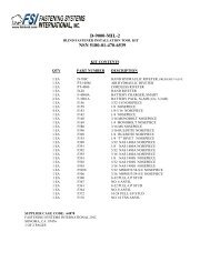
G750AKS SERVICE KIT<br />
QTY. PART NO. DESCRIPTION<br />
1 750A-033 BLADDER<br />
3 P-383 O-RING<br />
1 P-1313 SPRING<br />
2 P-112 O-RING<br />
2 P-650 BACK-UP RING<br />
1 P-1344 O-RING<br />
1 P-1345 BACK-UP RING<br />
1 P-299 O-RING<br />
1 P-869 BACK-UP RING<br />
1 P-1315 SPRING<br />
1 P-313 O-RING<br />
1 P-1347 BACK-UP RING<br />
1 P-1331 O-RING<br />
1 P-832 O-RING<br />
1 P-706 O-RING<br />
1 P-925 O-RING<br />
1 P-945 O-RING<br />
1 P-621 O-RING<br />
1 P-1007 O-RING<br />
1 P-1346 BACK-UP RING<br />
1 P-1294 O-RING<br />
1 P-1328 SPRING, RELEASE KNOB<br />
1 P-1365 SPRING, BYPASS<br />
1 P-1321 SPRING, VALVE CHECK<br />
1 P-1324 O-RING<br />
1 P-1324 O-RING<br />
1 P-1320 SPRING, SHIFT PRESSURE<br />
1 P-231 O-RING<br />
1 P-919 BACK-UP RING<br />
1 P-1381 SPRING<br />
1 P-1383 SPRING<br />
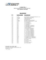
G750ACMR <strong>HAND</strong> <strong>RIVETER</strong><br />
<strong>NSN</strong> 5120-01-432-6190<br />
The Cherry G750ACMR hydraulic riveter tool kit includes the G750A with<br />
an H750A-456 pulling head, an adapter assembly, a right angle pulling<br />
head, an offset pulling head and a sturdy plastic carrying case.<br />
ITEM NO. QTY. PART NO. DESCRIPTION<br />
1 1 G750A <strong>HAND</strong> <strong>RIVETER</strong> (INCLUDES HEAD)<br />
2 1 H781-456 OFFSET PULLING HEAD<br />
3 1 H753A-456 RIGHT ANGLE PULLING HEAD<br />
4 1 750A-088 ADAPTER ASSEMBLY<br />
5 1 TLIT H781-456 H781-456 TOOL SET<br />
6 1 TLIT H753A-456 H753A-456 TOOL SET
ITEM N0. / DESCRIPTION QTY<br />
750-060 <strong>HAND</strong>LE SUBASSEMBLY<br />
1 750-061 MACHINED HOUSING 1<br />
2 P-510 SET SCREW 3<br />
3 P-383 O-RING 3<br />
4 P-1322 CAP SCREW 1<br />
5 750-031 PIN 1<br />
6 750-012 LEVEL 1<br />
7 P-1342 VINYL GRIP 1<br />
750-008 PLUNGER SUBASSEMBLY<br />
8 750-029 PLUNGER 1<br />
9 P-112 O-RING 2<br />
10 P-650 BACK-UP RING 1<br />
11 P-164 BALL 1<br />
12 P-1332 SPRING 1<br />
13 P-1333 HOLLOW LOCK 1<br />
14 750-013 DRAWBAR INSERT 1<br />
15 P-1346 BACK-UP RING 1<br />
16 P-1007 O-RING 1<br />
17 750-049 DRAWBAR 1<br />
18 750-111 NUT, LOCK 1<br />
19 750-015 PISTON 1<br />
20 P-621 0-RING 1<br />
21 P-945 0-RING 1<br />
22 P-1344 O-RING 1<br />
23 P-1345 BACK-UP RING 1<br />
24 P-869 BACK-UP RING 1<br />
25 P-299 0-RING 1<br />
26 750-020 SPRING BASE 1<br />
27 P-1315 SPRING, PISTON RETURN 1<br />
28 750-028 SHELL 1<br />
29 P-153 SOCKET HD. CAP SCREW 1<br />
30 750-030 NUT 1<br />
31 P-99 SET SCREW 1<br />
32 P-1294 O-RING 1<br />
33 P-573 CAP SCREW 1<br />
750-107 BLADDER SUB-ASSEMBLY<br />
34 750-033 BLADDER 1<br />
20 P-621 O-RING 1<br />
35 750-091 VENT PLUG 1<br />
36 P-1331 O-RING 1<br />
G750A PARTS LIST<br />
8<br />
ITEM N0. / DESCRIPTION QTY<br />
750-060 <strong>HAND</strong>LE SUBASSEMBLY<br />
750 -108 VALVE, RETURN SUBASSEMBLY<br />
37 750-022 SHIFT SPOOL 1<br />
38 P-919 BACK-UP RING 1<br />
39 P-231 O-RING 1<br />
40 750-023 POPPET 1<br />
41 P-313 O-RING 1<br />
42 P-1347 BACK-UP RING 1<br />
9 P-112 O-RING I<br />
10 P-650 BACK-UP RING 1<br />
43 P-1328 SPRING 1<br />
44 750-024 RELEASE KNOB 1<br />
45 750-025 SHIFT PIN 1<br />
46 P-1320 SHIFT PRESSURE SPRING 1<br />
47 750-036 SHIFT SPACER 1<br />
750-109 VALVE, CHECK SUB-ASSEMBLY<br />
48 750-026 CARTRIDGE COVER 1<br />
49 P-1324 O-RING 1<br />
50 P-1334 O-RING 1<br />
3 P-383 O-RING 1<br />
51 750-027 SCREW 1<br />
52 P-1321 VALVE CHECK SPRING 1<br />
53 P-117 BALL 1<br />
750-106 PRESSURE RELIEF VALVE<br />
54 750-065 BALL GUIDE 1<br />
11 P-164 BALL 1<br />
55 750-059 CHECK INSERT 1<br />
56 P-925 O-RING 1<br />
57 P-1383 SPRING 1<br />
58 750-064 SAFETY CHECK SCREW 1<br />
3 P-383 O-RING 1<br />
59 P-1384 WASHER 1<br />
60 P-1313 SPRING 1<br />
750-071 PULLING HEAD CHERRYMAX<br />
OTHER ATTACHMENTS AVAILABLE<br />
61 P-1381 SPRING 1<br />
62 P-832 O-RING 1<br />
63 750-067 JAW FOLLOWER 1<br />
64 701B18 JAWS, SET OF 2 1<br />
65 750-066 COLLET 1<br />
66 750-062 SLEEVE 1<br />
67 750-019 NOSE PIECE 1
G750A EXPLODED VIEW<br />
9
Note:<br />
This adapter is mounted on the G750A before<br />
attaching the H753A–456 Right Angle Pulling Head<br />
or the H781–456 Offset Pulling Head.<br />
ADAPTERS & PULLING HEADS<br />
10<br />
H750A-080 RIVNUT ADAPTER ASSEMBLY<br />
FOR G750A <strong>HAND</strong> <strong>RIVETER</strong><br />
750A-088 ADAPTER
H750A-8 PULLING HEAD FOR - 8<br />
DIA. CHERRYMAX ® INSTALLATIONS<br />
H750A-5MB/H750A-6MB PULLING HEADS FOR -5 AND<br />
-6 DIA. INSTALLATION OF MAXIBOLT BLIND BOLTS<br />
11
H782-( ) OFFSET PULLING HEAD<br />
The offset nose assembly permits installation of different<br />
sizes of:<br />
Pull through rivets, Bulb Type Blind Fasteners, Self<br />
Plugging Rivets, Blind Bolts, Single Action Wiredraw in<br />
limited access areas. See tool sheet for details.<br />
LOCTITE ® is a registered trademark of Henkel Corporation<br />
DEXRON ® is a registered trademark of GM Corporation.<br />
PARKER ® is a trademark of Parker Hannifin Corporation<br />
LUBRRIPLATE ® is a trademark of Fiske Brothers Refining Co.<br />
G750A WITH RIVNUT ADAPTER<br />
The G750A with Rivnut adapter permits installation of<br />
threaded inserts.<br />
H753A-456 RIGHT ANGLE PULLING HEAD<br />
The right angle nose assembly permits installation<br />
of -4, -5, -6 CherryMAX ® rivets in many applications that<br />
are inaccessible to a straight head.<br />
<strong>NSN</strong> 5130-01-393-2926<br />
H781-456 OFFSET PULLING HEAD<br />
The offset nose assembly permits installation of -4, -5, -6<br />
CherryMAX ® rivets in limited access areas.<br />
<strong>NSN</strong> 5130-01-393-2925<br />
WARRANTY<br />
Seller warrants the goods conform to applicable specifications and drawings and will be manufactured and inspected according to generally accepted practices of<br />
companies manufacturing industrial or aerospace fasteners. In the event of any breach of the foregoing warranty, Buyer’s sole remedy shall be to return defective<br />
goods (after receiving authorization from Seller) for replacement or refund of the purchase price, at the Seller’s option. Seller agrees to any freight costs in<br />
connection with the return of any defective goods, but any costs relating to removal of the defective or nonconforming goods or installation of replacement goods<br />
shall be Buyer’s responsibility. SELLER’S WARRANTY DOES NOT APPLY WHEN ANY PHYSICAL OR CHEMICAL CHANGE IN THE FORM OF THE<br />
PRODUCT IS MADE BY BUYER.<br />
THE FOREGOING EXPRESS WARRANTY AND REMEDY ARE EXCLUSIVE AND ARE IN LIEU OF ALL OTHER WARRANTIES AND REMEDIES;<br />
ANY IMPLIED WARRANTY AS TO QUALITY, FITNESS FOR PURPOSE, OR MERCHANTABILITY IS HEREBY SPECIFICALLY DISCLAIMED AND<br />
EXCLUDED BY SELLER. THIS WARRANTY IS VOID IF SELLER IS NOT NOTIFIED IN WRITING OF ANY REJECTION OF THE GOODS WITHIN ONE<br />
(1) YEAR AFTER INITIAL USE BY BUYER OF ANY POWER <strong>RIVETER</strong> OR NINETY (90) DAYS AFTER INITIAL USE OF ANY OTHER PRODUCT.<br />
Seller shall not be liable under any circumstances for incidental, special or consequential damages arising in whole or in part from any breach by Seller, AND SUCH<br />
INCIDENTAL, SPECIAL, OR CONSEQUENTIAL DAMAGES ARE HEREBY EXPRESSLY EXCLUDED.<br />
For more information please contact our Technical Services Department at Tel. 714-850-6022<br />
1224 East Warner Ave,<br />
Santa Ana, CA 92705<br />
Tel: 1-714-545-5511<br />
Fax: 1-714-850-6093<br />
www.cherryaerospace.com<br />
© 2007 Cherry Aerospace Supplier’s Federal Identification Code: 11815 TM-G750A<br />
Rev.: D<br />
12<br />
Date: 10/25/07<br />
CR# 07-0376