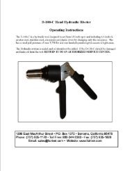
ORIGINAL INSTRUCTIONS HAND HYDRAULIC RIVETER NSN ...
ORIGINAL INSTRUCTIONS HAND HYDRAULIC RIVETER NSN ...
ORIGINAL INSTRUCTIONS HAND HYDRAULIC RIVETER NSN ...

Create successful ePaper yourself
Turn your PDF publications into a flip-book with our unique Google optimized e-Paper software.
USING THE ADAPTER<br />
(See page 9 for G750A assembly drawings)<br />
When installing the 750A-088 adapter, remove the outer<br />
sleeve (66) and collet (65) with spring (27), Jaws (64), jaw<br />
follower (63), and jaw follower spring (61).<br />
The large collet spring (27) must be positioned over the drawbar<br />
extension adapter before threading on the drawbar (17). (This<br />
spring can be removed from the collet by turning<br />
counterclockwise.) Install the outer portion of the adapter sleeve<br />
making certain of full thread engagement on both parts.<br />
When replacing the outer sleeve (750-016), cycle the lever one or<br />
two times allowing easier thread engagement.<br />
Before installing the accessory heads, make certain the drawbar<br />
is fully extended to ensure full thread engagement.<br />
The tool is now ready to accept the H753A-456 or H781-456.<br />
(See page 6)<br />
MAINTENANCE DISASSEMBLY<br />
To facilitate assembly, it is recommended that you have on hand<br />
a Cherry G750KT Tool Kit. The G750KS Service Kit contains<br />
replacement O-rings, jaws, jaw follower, bumper, bladder, seals<br />
and springs to replace worn or damaged parts.<br />
For complete disassembly of the G750A tool, please follow the<br />
instructions indicated.<br />
Unscrew sleeve (66) and remove. If piston rotates while loosening<br />
sleeve, pump tool to end of stroke and continue to remove.<br />
Carefully remove screws (4) and (33) vent plug (35), and bladder<br />
(34). CAUTION: Screws (4) & (33) are under pressure and<br />
will spray.<br />
Drain the remaining fluid by depressing release knob (44).<br />
Use collet cap (750-045) to remove collet (65) and remove nut<br />
lock (18) spring base (26) piston return spring (27) jaw follower<br />
spring (61) bumper ring (62) jaw follower (63) and jaws (64).<br />
Screw the sleeve (66) into the piston (19) and pull the piston out<br />
of the housing. Using a 7/8" hex deep socket wrench, unscrew nut<br />
(30) then unscrew drawbar (17) and remove. Note: The drawbar<br />
(17) has a left hand thread. (Turn clockwise to remove).<br />
When removing the drawbar from the housing, usually the nut<br />
(30) and the insert (14) will stay with it. These items can be<br />
separated once removed from the housing. Remove the spring<br />
(60). Depress the lever (6) to push the plunger (8) through the<br />
housing, then remove the plunger. Remove screw (29) and<br />
remove shell (28). Remove screw (31) pin (5) and lever (6).<br />
If necessary, remove screw (58), ball (11), ball guide (54) spring<br />
(57) and O-ring (3). Remove cartridge cover (48) using 7/8"<br />
wrench. Remove spacer (47), spring (46) and shift pin (45).<br />
Using a small, flat screw driver to hold the poppet (40) to prevent<br />
rotation, unscrew the knob (44) and remove the spring (43).<br />
NOTE: The knob (44) is Lock-Tite sealed at the factory and<br />
may require extra effort to unscrew. Using a 3/8" diameter<br />
rod, push gently on shift spool (37) and remove with poppet (40)<br />
seals (10,9,38,39,41) and (42). Poppet (40) can be separated<br />
from the shift spool once removed from the housing by<br />
applying<br />
4<br />
thumb pressure on the threaded end. NOTE: seals (41, 42) must<br />
be removed from the small diameter end of the spool.<br />
If necessary, unscrew spring retainer screw (51) and remove<br />
spring (52) and ball (53).<br />
CAUTION: Do not open or remove set screws (2). These<br />
are permanently factory sealed plugs.<br />
All parts should be cleaned and inspected for damage or wear.<br />
O-rings, seals and springs should be replaced as needed.<br />
ASSEMBLY<br />
When replacing O-rings and seals use assembly tools from the<br />
G750KT Tool Kit to avoid damage to the seals. Lubricate all seals<br />
and O-rings before installation.<br />
Replace O-ring (36) on vent plug (35) pull bladder (34) over end<br />
of vent plug (35) then place O-ring (20) over bladder (34) and<br />
carefully insert into housing cavity. Thread vent plug into<br />
housing.<br />
Place O-ring (3) on screw (4) and screw into housing.<br />
Place O-ring (56) on insert (55) and screw the insert into the<br />
cavity located under the Cherry logo. Place ball (11) and ball<br />
guide (54) and washer (59) on the ball guide stem (54). Place<br />
spring (57) on top of the washer into the cavity of the insert (55).<br />
Place O-ring (3) on the screw (58) and place in the cavity to<br />
contain the above components. NOTE: If tool does not develop<br />
maximum power, additional washers (59) are required.<br />
NOTE: If your tool is the G750A- 080R, the adjustable<br />
knob (750-095), will replace the screw (58) and O-ring<br />
(3). This adjustable control valve is intended to prevent<br />
the stripping of the insert threads by restricting the<br />
pulling force.<br />
Place O-rings (39), (9) and back-up rings (38), (10) on<br />
shift spool (37). Make sure O-rings are toward the center of the<br />
spool and the back-up rings are toward the ends. Use<br />
assembly tool (750–043) to insert sub-assembly shift spool into<br />
the housing. Make sure that the spool is generously lubed and<br />
fully inserted to the end of the cavity.<br />
Place poppet (40) into shift spool (37) supporting with small<br />
screw driver while placing O-ring (41) and back-up ring (42) on<br />
poppet (40) from the left hand side of the tool. Carefully screw<br />
the release knob (44) without spring (43) to push and seat seal<br />
onto the poppet (40). Place spring (43) adding a small drop of<br />
#242 Lock-tite or equivalent on the threaded end of the poppet<br />
(40). Screw the release knob (44) onto poppet (40).<br />
Allow the Lock-tite to cure for 2 hours before use. There is no<br />
need to rotate the knob after assembly. To return or retract the<br />
piston to original position, push in the knob.<br />
Drop ball (53) and spring (52) in cartridge cover and secure with<br />
screw (51) with O-ring (3) on it. Place spring (46) on shift pin.<br />
With needle nose pliers, place the shift pin (45) in recess of the<br />
spool (37). Place spring (46) on shift pin. Apply lube to spacer (47)<br />
and place it in cartridge cover (48). Screw the cartridge cover<br />
assembly (48) into the housing.<br />
Place seals (21) and (20) on the drawbar (17) and insert O-ring<br />
(16) with back-up ring (15) into the drawbar (17). Plunger (8)<br />
with drawbar insert (14) can be used to facilitate this. Place