
You also want an ePaper? Increase the reach of your titles
YUMPU automatically turns print PDFs into web optimized ePapers that Google loves.
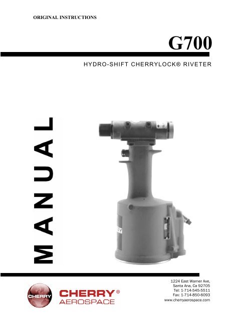
ORIGINAL INSTRUCTIONS<br />
G700<br />
HYDRO-SHIFT CHERRYLOCK® RIVETER<br />
1224 East Warner Ave,<br />
Santa Ana, Ca 92705<br />
Tel: 1-714-545-5511<br />
Fax: 1-714-850-6093<br />
www.cherryaerospace.com
G700 HYDRO-SHIFT INSTRUCTIONS<br />
TABLE OF CONTENTS<br />
Description ......................................................................................... 1<br />
Tool Capacity Chart ............................................................................. 1<br />
Safety Warnings ................................................................................ 2<br />
G700 Exploded View........................................................................... 3<br />
G700 Component List ......................................................................... 4<br />
Fill and Bleed Instructions ..................................................................... 4<br />
Adjustment Instructions ........................................................................ 5<br />
Shift Point Setting ...................................................................... 5<br />
Shift Piston Check .................................................................... 5<br />
Operating Instructions .......................................................................... 6<br />
Installing H681 Series Pulling Heads on <strong>Rivet</strong>er ............................ 6<br />
Maintenance and repair ....................................................................... 6<br />
Fill and bleed ...................................................................................... 6<br />
Trouble Shooting ................................................................................. 6<br />
Warranty and Contact Information......................................................... 7
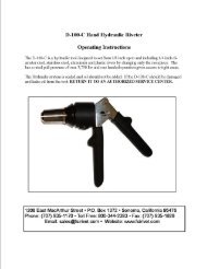
The Cherry G-700 Hydro-Shift <strong>Rivet</strong>er is a<br />
pneumatic-hydraulic tool designed<br />
specifically for the most efficient installation<br />
of Cherry-lock <strong>Rivet</strong>s. It weighs only 5 3/4<br />
lbs. and can be operated in any position with<br />
one hand.<br />
The G-700 is 10 5/8" high, has a 29/32"<br />
stroke and will install all the rivets shown<br />
below on 90 to 120 psi of air pressure at the<br />
tool.<br />
Pulling heads are not furnished with<br />
this tool but must be ordered<br />
separately. In ordering heads be sure<br />
to specify the shank diameter and<br />
head style (universal or countersunk)<br />
of the rivets to be installed.<br />
H681 Series pulling heads fit directly on<br />
this tool to install both bulbed and<br />
standard NAS type 2000 Series Cherrylock <strong>Rivet</strong>s.<br />
DESCRIPTION<br />
TOOL C AP AC I TY CH AR T<br />
The numbers shown in the rivet columns below are the maximum grip length that can be installed with this<br />
tool. Dashes indicate those rivet sizes which cannot be installed in any grip length.<br />
PULLING<br />
HEAD<br />
H681<br />
DIAMETER<br />
ALUMINUM MONEL ST STEEL<br />
2163<br />
2263<br />
2162<br />
2262<br />
2563 2562<br />
2643<br />
2653<br />
2663<br />
1<br />
2642<br />
2652<br />
2662<br />
UNI CTSK UNIV. CTSK. UNIV. CTSK<br />
V. . HEAD HEAD HEAD .<br />
-4 8HEA HEA 9 8 9 8 HEAD 9<br />
-5 8 9 8 9 8* 9*<br />
-6 8 9 - - - -<br />
-8 - - - - - -<br />
*May require 95 lbs. psi air pressure at tool.<br />
PULLING<br />
HEAD<br />
H681<br />
BULBED CHERRYLOCK<br />
(NAS 1738 & 1739)<br />
RIVET<br />
DIAM.<br />
ALUMINUM MONEL<br />
2239<br />
2249<br />
UNIV.<br />
HEAD<br />
2238<br />
2248<br />
2539 2538<br />
CTSK. UNIV.<br />
HEAD HEAD<br />
CTSK.<br />
HEAD<br />
-4 ALL ALL ALL ALL<br />
-5 - - - -<br />
-6 - - - -
SAFETY WARNINGS<br />
Approved eye protection should be worn when operating, repairing, or overhauling this tool.<br />
Do not use beyond the design intent.<br />
Do not use substitute components for repair.<br />
Any modification to the tool, pulling heads, accessories or any component supplied by CHERRY ® , or<br />
their representatives, shall be the customer’s entire responsibility.<br />
CHERRY ® will be pleased to advise on any proposed modification.<br />
The tool must be maintained in a safe working condition at all times and examined at regular intervals for<br />
damage.<br />
Before disassembling the tool for repair, refer to the maintenance instructions.<br />
All repairs shall be undertaken only by personnel trained in CHERRY ® installation tools.<br />
Contact CHERRY ® with your training requirement.<br />
Always disconnect the air line from the tool inlet before attempting to service, adjust, fit or remove any<br />
accessory.<br />
Do not operate the tool when it is directed at any person.<br />
Ensure that the vent holes do not become blocked or covered and that air line hoses are always in good<br />
condition.<br />
Excessive contact with the hydraulic oil should be avoided to minimize the possibility of rashes. Care should be<br />
taken to wash thoroughly.<br />
Operating air pressure should not exceed 110 psi (7,6 bar).<br />
Do not operate the tool without the pulling head in place.<br />
Do not operate the tool unless the handle base (48) is fully secured by the retaining ring (49).<br />
All retaining rings, screwed end caps, air fittings, trigger valves and pulling heads should be attached<br />
securely and examined at the end of each working shift.<br />
Do not pull rivet in the air.<br />
The precautions to be used when using this tool must be explained by the customer to all operators. Any<br />
question regarding the correct operation of the tool and operator safety should be directed to CHERRY ® .<br />
Do not pound on the rear of the tool head to force rivets into holes as this will damage the tool.<br />
Do not depress the trigger while disconnecting the air bleeder and replacing the cap screws (38) when<br />
bleeding the tool.<br />
Do not release the trigger after installing a CherryLOCK ® rivet until the tool is positioned away from the<br />
structure or personnel. Upon release of the trigger the stem will eject from the front of the pulling head with<br />
moderate force.<br />
2
G700 – EXPLODED VIEW<br />
3
REF<br />
PARTS LIST FOR THE G-700 RIVETER<br />
PART<br />
NUMBER<br />
DESCRIPTION QTY<br />
1 680A103 Sleeve Cap 1<br />
2 680A105 Spring 1<br />
3 700B32 Front Cap 1<br />
4 P652 Back-Up Ring 1<br />
5 P826 O-Ring, Disogrin (No Subs.) 1<br />
6 P837 O-Ring, Disogrin (No Subs.) 4<br />
7 700A38 Piston Stop 1<br />
8 700B37 Shift Piston Cap 1<br />
9 P724 O-Ring 1<br />
10 P651 Back-Up Ring 1<br />
11 P828 O-Ring, Disogrin (No Subs.) 1<br />
12 700B34 Head Piston 1<br />
13 P216 Quad Ring 1<br />
14 P676 Back-Up Ring 1<br />
15 680A111 Valve Spring 1<br />
16 *700A41 Valve Stem 1<br />
17 P706 O-Ring 1<br />
18 P194 O-Ring 1<br />
19 *700A40 Valve Seat 1<br />
20 700A35 Spring, Head Piston 1<br />
21 700B36 Shift Piston 1<br />
22 P814 Retaining Ring, 1<br />
23 *700A57 Stroke Adjuster 1<br />
24 P650 Back-Up Ring, 1<br />
25 P829 O-Ring, Disogrin 4<br />
26 700A58 Adjuster Pin 1<br />
27 700A72 Release Assembly 1<br />
28 P723 O-Ring 1<br />
29 700B33 Rear Cap 1<br />
30 P841 Set Screw 1<br />
31 P728 O-Ring 1<br />
32 P732 Back-Up Ring 1<br />
33 700A48 Adjuster Ring 1<br />
34 700A49 Adjuster Knob 1<br />
35 P831 O-Ring, Disogrin (No Subs.) 1<br />
36 700C2 Head Cylinder 1<br />
* These three parts cannot be purchased separately<br />
but must be ordered as a set, part number 700A56<br />
Valve Assembly (which also includes P829, P194,<br />
P650 & P706).<br />
4<br />
REF PART<br />
DESCRIPTION<br />
NUMBER<br />
QTY<br />
37 P572 Stat-O-Seal 2<br />
38 P573 Button Head Screw 2<br />
39 P838 O-Ring, Disogrin (No Subs.) 2<br />
40 P115 Back-Up Ring 2<br />
41 P727 O-Ring 1<br />
42 700B93 Packing Plug 1<br />
43 P731 Back-Up Ring 2<br />
44 P730 Quad Ring 1<br />
45 700B6 Air Piston 1<br />
46 P737 Conelok Nut,1/8-20 1<br />
47 P725 O-Ring 1<br />
48 70084 Handle Base 1<br />
49 P735 Retaining Ring, Spir-O-Lox 1<br />
50 70085 Base Cover 1<br />
51 P736 Retaining Ring, Spir-O-Lox 1<br />
52 P832 O-Ring, Disogrin (No Subs.) 1<br />
53 700A22 Gasket 1<br />
54 703A33 Trigger Assembly (Includes P223) 1<br />
55 P223 O-Ring 1<br />
56 P27 Soc. Hd. Cap Screw 4<br />
57 700D3 Handle 1<br />
58 P734 Retaining Ring, Spir-O-Lox 1<br />
59 700B7 Power Cylinder 1<br />
60 P833 O-Ring, Disogrin (No Subs.) 2<br />
61 P739 Back-Up Ring 1<br />
62 P294 O-Ring 1<br />
63 700A8 Power Piston & Rod 1<br />
64 P653 O-Ring 4<br />
65 700873 Valve Sleeve 1<br />
66 700A67 Spring 1<br />
67 700A15 Valve Spool 1<br />
68 P834 O-Ring, Disogrin<br />
2<br />
69 700A16 (No Valve Substitutes) Plug 1<br />
70 700A17 Muffler 1<br />
71 P279 Retaining Ring, Spir-O-Lox 1
1. Remove knurled cap (A) from front of riveter head.<br />
2. Place jaw assembly (D) inside collet (C).<br />
3. Insert spring end of jaw assembly into hole in<br />
head piston (12). Apply enough pressure to<br />
engage collet threads. Turn until the collet<br />
bottoms on shoulder of piston and the “collet<br />
lock” snaps into the slot in piston.<br />
Hand tightening is sufficient.<br />
SHIFT POINT SETTING<br />
OPERATING INSTRUCTIONS<br />
INSTALLING H681 PULLING HEAD ON RIVETER<br />
6 8 0 A1 5 9 S e t t i n g G a g e<br />
5<br />
Note: To remove the collet, push the lock back<br />
into collet (using a blunt pointed tool) while turning<br />
the collet counterclockwise.<br />
4. Place sleeve assembly (B) over the collet<br />
and head piston. Slip knurled cap (A) over the<br />
sleeve assembly and hand tighten onto end of<br />
riveter head. Extensions for the H681 pulling heads<br />
can be ordered in lengths of 2", 6", 12" and 24".<br />
This adjustment determines the flushness of break of the rivet stem. The setting controls the point at which the reac- tion<br />
load is transferred from the rivet head to the lock ring of the rivet. After the lock ring is inserted the rivet stem will break<br />
flush. The setting gage (680A159) is included with the tool. To adjust setting:<br />
AD J U S TM E N T I N STRUCTI O N S<br />
1. Connect tool to air hose with a minimum of 90 psi and<br />
remove pulling head and sleeve cap.<br />
2. Screw small end of 680A159 gage onto head piston<br />
(12) until hand-tight.<br />
3. Cycle tool and hold trigger so that the gage is pulled into<br />
the tool head. Gage Point #1 should be flush with the<br />
front of tool head as shown in the sketch.<br />
4. Release trigger and turn adjuster knob (34) clockwise to<br />
increase gage protrusion or counter-clockwise to decrease<br />
gage protrusion. Cycle the tool after each adjustment and<br />
check the gage point until it lines up flush with tool head. A<br />
limit pin restricts adjustment to one-half turn of knob in either<br />
direction from factory setting.<br />
CAUTION: Always release the tool trigger before turning knob.<br />
G-700 HEAD
SHIFT PISTON CHECK<br />
The shift piston check is made to ascertain that the movement of the piston is not restricted in any manner.<br />
It must be free to move the amount indicated below in order to obtain proper installation.<br />
1. Connect tool to air hose with a minimum of 90 psi and<br />
remove pulling head and sleeve cap.<br />
2. Insert large (unthreaded) end of 680A159 gage over tool<br />
piston until it seats in the tool head. With trigger<br />
released, the front of the tool head must be within the<br />
gage groove recess, Gage Point #2, as shown in sketch.<br />
3. Cycle tool and hold the trigger. The gage should move<br />
forward at the completion of the cycle and in this position<br />
the single gage line, Gage Point #3, must be visible or<br />
forward of the front of the tool head as shown in sketch.<br />
The tool may be cycled while holding the gage in position.<br />
4. No outside adjustments can be made to correct any<br />
deviations from the above gage positions. Failure of the tool<br />
to comply with these gage relationships indicates<br />
incorrect tool performance and it should be sent to the<br />
Service Department for correction.<br />
ANVIL SETTING —The anvil setting on the G-700 tool is<br />
factory set and does not require adjusting.<br />
MAINTENANCE AND REPAIR<br />
The G-700 <strong>Rivet</strong>er has been manufactured to give maximum service with minimum care. In order that<br />
this may be accomplished, the following recommendations should be followed.<br />
1. The hydraulic system should be full of oil and free from air at all times.<br />
2. Keep excessive moisture and dirt out of the air supply to prevent wear of the air valve.<br />
3. Do not pound on the rear of the tool head to force rivets into holes as this will damage the adjusting mechanism.<br />
4. Make sure the pulling head is correctly and securely attached.<br />
TO FILL RIVETER WITH OIL<br />
1. Connect the tool to an air line and remove two cap screws (38) located on the side of the head.<br />
2. Using a pressure oil can filled with Automatic Transmission Fluid, Type A (no substitute), force the fluid into the top<br />
hole until it flows freely from the bottom hole. Reverse the procedure until air bubbles cease appearing at either hole.<br />
3. Replace both cap screws, cycle the trigger several times and then repeat steps 1 and 2 above. (Do not pull the<br />
trigger with the cap screws removed as you may be sprayed with oil).<br />
4. To insure the positive removal of all air from the hydraulic system; use Cherry Air Bleeder No. 700A77.<br />
TROUBLE SHOOTING<br />
1.Check air line for correct pressure at the tool. It must be 90 to 110 psi.<br />
2.Check tool for lack of hydraulic fluid. (See above.)<br />
3.Check for oil leakage.<br />
a. Oil leaking around the cap screws (38) in the head indicates that the screws are loose or the washer<br />
gaskets (37) need replacing.<br />
b. If oil should leak through the by-pass hole at the base of the handle (57) the O-Rings (40) are<br />
worn or damaged.<br />
c. Oil leaking from the front of the head (36) indicates that O-Rings (5) are worn or damaged.<br />
d. If head is taken apart for repair exercise caution in removing piston cap (8) since it contains the<br />
piston spring (20) which may be ejected forcefully. Check all O-Rings and carefully clean all<br />
parts before reassembling.<br />
6
Be sure to make any replacements with the exact O-Rings shown in the parts list to insure that the<br />
correct material and hardness is used.<br />
4.Tighten the end caps (3&29) securely at 150/ 180 ft –lbs.<br />
CAUTION: Valve parts (16, 19 & 23) are matched parts and must be kept together or replaced as a complete unit.<br />
Check air valve for leakage. If air is escaping, remove retaining ring (71) and muffler (70) Insert a 5/16"-18 threaded<br />
rod or bolt into end of valve plug (69) and pull it out. Using the same procedure pull out spool (67). Replace O-Rings<br />
(25) & 68) and reassemble.<br />
Note: It should never be necessary to remove the valve sleeve (65) unless the air supply has become so<br />
badly contaminated that the ports in the sleeve are plugged up. If this unlikelihood should occur, carefully<br />
remove spring (66) from its groove, using extreme caution not to distort the coils of the spring. Remove<br />
sleeve (65), clean thoroughly, replace O-Rings (64) and reassemble, making sure that spring (66) is seated in<br />
its groove correctly, otherwise valve will not function.<br />
5.Check movement of piston (12). If it does not move freely or is slow in operation:<br />
a. Valve (16) may be held off its seat (19) by contaminants, allowing oil to by-pass. Drain gun,<br />
flush thoroughly and refill with fresh oil.<br />
b. O-Rings (13) or (62) may be damaged and require replacement.<br />
c. Piston (12) may be mechanically locked due to damaged parts.<br />
d. Power piston may - be held off its seat on rod (63) allowing oil to by-pass; see above for<br />
cleaning (paragraph a)<br />
e. Muffler (70) or air filter inside spool (67) may be plugged with dirt.<br />
Clean them thoroughly with normal solvent and back-blow with compressed air.<br />
6. Check movement of shift piston (21).<br />
If it does not move freely:<br />
a. Small holes in screen in piston (27) may be plugged preventing oil flow; see above (5a).<br />
b. Hole through valve (16) may be plugged; see above (5a).<br />
NOTE: We recommend the purchase of a<br />
G-700KS Service Kit which contains various gaskets, O-Rings, washers and similar parts likely to need<br />
replacing in time.<br />
WARRANTY<br />
Seller warrants the goods conform to applicable specifications and drawings and will be manufactured and inspected according to generally accepted practices of<br />
companies manufacturing industrial or aerospace fasteners. In the event of any breach of the foregoing warranty, Buyer’s sole remedy shall be to return defective<br />
goods (after receiving authorization from Seller) for replacement or refund of the purchase price, at the Seller’s option. Seller agrees to any freight costs in<br />
connection with the return of any defective goods, but any costs relating to removal of the defective or nonconforming goods or installation of replacement goods<br />
shall be Buyer’s responsibility. SELLER’S WARRANTY DOES NOT APPLY WHEN ANY PHYSICAL OR CHEMICAL CHANGE IN THE FORM OF THE<br />
PRODUCT IS MADE BY BUYER.<br />
THE FOREGOING EXPRESS WARRANTY AND REMEDY ARE EXCLUSIVE AND ARE IN LIEU OF ALL OTHER WARRANTIES AND REMEDIES;<br />
ANY IMPLIED WARRANTY AS TO QUALITY, FITNESS FOR PURPOSE, OR MERCHANTABILITY IS HEREBY SPECIFICALLY DISCLAIMED AND<br />
EXCLUDED BY SELLER. THIS WARRANTY IS VOID IF SELLER IS NOT NOTIFIED IN WRITING OF ANY REJECTION OF THE GOODS WITHIN ONE<br />
(1) YEAR AFTER INITIAL USE BY BUYER OF ANY POWER RIVETER OR NINETY (90) DAYS AFTER INITIAL USE OF ANY OTHER PRODUCT.<br />
Seller shall not be liable under any circumstances for incidental, special or consequential damages arising in whole or in part from any breach by Seller, AND SUCH<br />
INCIDENTAL, SPECIAL, OR CONSEQUENTIAL DAMAGES ARE HEREBY EXPRESSLY EXCLUDED.<br />
For more information please contact our Technical Services Department at Tel. 714-850-6022<br />
LOCTITE ® is a registered trademark of Henkel Corporation<br />
DEXRON ® is a registered trademark of GM corporation.<br />
PARKER ® is a trademark of Parker Hannifin Corporation<br />
LUBRRIPLATE ® is a trademark of Fiske Brothers Refining Co.<br />
1224 East Warner Ave,<br />
Santa Ana, Ca 92705<br />
Tel: 1-714-545-5511<br />
Fax: 1-714-850-6093<br />
www.cherryaerospace.com<br />
© 2007 Cherry Aerospace Supplier’s Federal Identification Code: 11815 TM-G700<br />
7<br />
Rev.: A<br />
Date: 05/09/07<br />
CR# 07-0097