FABRICATION TOOLS FOR CORRUGATED WEB I-BEAMS - AISC
FABRICATION TOOLS FOR CORRUGATED WEB I-BEAMS - AISC
FABRICATION TOOLS FOR CORRUGATED WEB I-BEAMS - AISC

You also want an ePaper? Increase the reach of your titles
YUMPU automatically turns print PDFs into web optimized ePapers that Google loves.
<strong>FABRICATION</strong> <strong>TOOLS</strong> <strong>FOR</strong><br />
<strong>CORRUGATED</strong> <strong>WEB</strong> I-<strong>BEAMS</strong><br />
A machine tool manufacturer in Austria has developed<br />
an economical method to positively weld light gauge<br />
corrugated webs to hot rolled steel plate flanges<br />
Modern Steel Construction / July 1999<br />
ONE OF THE FUTURE DEVEL-<br />
OPMENTS IN STRUCTURAL<br />
STEEL OFTEN TOUTED at<br />
steel conferences during the past<br />
few years has been the imminent<br />
availability of corrugated web Ibeams.<br />
One Austrian company,<br />
Zeman + Co in Vienna, is now<br />
manufacturing machinery to economically<br />
produce built-up girders<br />
consisting of plate flanges<br />
welded to a corrugated web.<br />
Engineers have long realized<br />
that corrugations in webs enormously<br />
increase their stability<br />
against buckling and can result<br />
in very economical designs.<br />
Therefore, Corrugated Web I-<br />
Beams have the potential to<br />
eliminate many costly web stiffeners.<br />
In addition, the use of<br />
thinner webs results in less raw<br />
material cost—with savings estimated<br />
at 10-30% compared with<br />
conventional built-up sections<br />
and more than 30% compared<br />
with standard I-beams.<br />
Corrugated Web I-Beams provide<br />
a high strength-to-weight<br />
ratio and reduce the depth of<br />
steel when compared to truss<br />
systems—while also reducing<br />
costs as the clear spans increase.<br />
Finally, erection costs may be<br />
reduced. Since the corrugation in<br />
the web provides the members<br />
with a higher resistance against<br />
bending over the weak axis and<br />
rotation, none of the auxiliary<br />
lifting equipment normally needed<br />
is required when unloading<br />
the beam and lifting it into its<br />
final position. The same resistance<br />
against rotation also<br />
reduces the need for brace angles
or tubes, further reducing erection<br />
cost and time.<br />
The newly available method of<br />
producing these members, consisting<br />
of light gage corrugated<br />
webs welded to hot-rolled plate<br />
flanges, is a continuous process<br />
for high volume requirements.<br />
Corrugated Web I-Beams have<br />
been used in a variety of applications,<br />
ranging from a simple<br />
span in a one-story building to a<br />
load-bearing component in a<br />
multi-story building. In addition,<br />
the rigidity of the webs makes<br />
the Corrugated Web I-Beam<br />
effective in the crane beam market<br />
and may even be usable as<br />
box girders for the design of<br />
bridge cranes. Finally, it is<br />
expected that Corrugated Web I-<br />
Beams will prove useful in the<br />
highly competitive short-span<br />
bridge market.<br />
Using the Zeman + Co. system,<br />
the flanges of Corrugated<br />
Web I-Beams are made from<br />
steel plate or bar material. The<br />
flange width may be different<br />
between the upper and the bottom<br />
flange; however, each width<br />
has to be maintained over the<br />
length of the beam. They may<br />
have step downs in the flange<br />
thickness and the flange dimensions<br />
vary between 120 mm<br />
width by 5 mm thickness up to a<br />
flange size of 450 mm width by<br />
30 mm thickness.<br />
The webs are taken from coil<br />
material that is continuously<br />
corrugated to a sine curve. The<br />
depth of the corrugation should<br />
measure between 30 mm and 45<br />
mm, but can also have other<br />
dimensions. The web sizes may<br />
range from 1.5 mm to 3 mm in<br />
thickness and 200 mm to 1500<br />
mm in height.<br />
The minimum length of a<br />
Corrugated Web I-Beam is 6.00<br />
m and the maximum length is<br />
20.00 m.<br />
DESIGN PREMISES<br />
The corrugation of the web<br />
generally avoids failure of the<br />
beam due to loss of web stability<br />
before the plastic limit-loading is<br />
reached. However as a result of<br />
the corrugation the web does not<br />
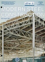
The European projects shown above and on the opposite page (bottom) utilize<br />
Corrugated Web I-Beams for both columns and girders. The Corrugated Web I-<br />
Beams have been used in Europe on a wide range of projects, ranging from<br />
supermarkets to industrial buildings.<br />
Pictured on the opposite page (top) is the machinery used to produce the corrugated<br />
webs.<br />
Modern Steel Construction / July 1999
participate in the transfer of longitudinal<br />
normal forces from<br />
bending. This means that the<br />
Corrugated Web I-Beam behaves<br />
like a lattice girder in which the<br />
bending moments and the normal<br />
forces are transferred via<br />
the flanges, while the transverse<br />
forces are transferred through<br />
the diagonals and verticals of the<br />
lattice girder (in this case, the<br />
corrugated web.)<br />
On the basis of static analogy<br />
dimensioning and testing, the<br />
verification of the load carrying<br />
capacity is ideally provided at<br />
the level of internal forces and<br />
the cross section properties of<br />
the individual cross section components—flange<br />
and web.<br />
Modern Steel Construction / July 1999<br />
Zeman + Co. has developed<br />
substantial design information<br />
to aid engineers in calculating<br />
load capacities and member<br />
dimensions. For more information,<br />
contact the authors via the<br />
information at the end of this<br />
article.<br />
<strong>FABRICATION</strong><br />
The Corrugated Web I-Beam<br />
is being assembled in the course<br />
of a continuous and highly automated<br />
manufacturing process.<br />
At the beginning of the assembly<br />
line a decoiler feeds the thin web<br />
material into a stretch leveler for<br />
stress reduction before the flat<br />
material is fed into the corrugating<br />
unit. After the corrugation<br />
has been induced and after the<br />
desired length of the web has<br />
been fabricated, the web is cut<br />
off by means of a flying shear.<br />
While the finished web is<br />
transported through the assembly<br />
line continuously, both<br />
flanges—which were preassembled<br />
in a separate process—are<br />
put in place and fixed to the web<br />
by means of a hydraulic device.<br />
Together they pass the welding<br />
unit where the flanges and the<br />
web are welded together under<br />
submerged arc. Speed and angle<br />
of the welding pistol are automatically<br />
controlled in order to<br />
achieve a high quality one sided<br />
weld. The entire manufacturing<br />
process takes place at a speed of<br />
2 m/minute.<br />
Splice plates or other accessories<br />
then complete the finished<br />
beam before it receives its corrosion<br />
protection.<br />
Walter Siokola is General<br />
Manager of Zeman + Co. in<br />
Vienna, Austria. Hans Poeter is<br />
an engineering consultant in<br />
Siegen, Germany.