Pressure Booster Pumps - Pure Aqua Inc
Pressure Booster Pumps - Pure Aqua Inc
Pressure Booster Pumps - Pure Aqua Inc

Create successful ePaper yourself
Turn your PDF publications into a flip-book with our unique Google optimized e-Paper software.
Installation (Continued)<br />
!<br />
Hazardous<br />
voltage. Can<br />
shock, burn or<br />
cause death.<br />
Ground pump<br />
before connecting<br />
to power supply.<br />
Ground motor<br />
before connecting to<br />
electrical power supply.<br />
Failure to ground<br />
motor can cause<br />
severe or fatal electrical<br />
shock hazard.<br />
Do not ground to<br />
a gas supply line.<br />
Proper rotation of<br />
pump impeller is critical on three phase<br />
motors. See Motor Rotation under<br />
Operation section and Figure 12.<br />
WIRING<br />
1. Install, ground, wire and maintain<br />
this pump in accordance with your<br />
local electrical code and all other<br />
codes and ordinances that apply.<br />
Consult your local building inspector<br />
for local code information.<br />
2. Ground the pump permanently using<br />
a wire of size and type specified<br />
by local or United States National<br />
Electrical Code. Do not ground to<br />
a gas supply line.<br />
3.Connect ground wire first. Connect<br />
to ground first, then to green grounding<br />
terminal provided on the motor<br />
frame, identified as GRD. Ground connection<br />
MUST be made to this terminal.<br />
Do not connect motor to electrical<br />
power supply until unit is permanently<br />
grounded; otherwise serious or fatal<br />
electrical shock hazard may be caused.<br />
4. Connect the other end of the ground<br />
wire to a properly grounded service<br />
panel or to a control panel ground<br />
bar if it is connected to the power<br />
supply ground.<br />
IMPORTANT: Check local and/or<br />
United States National Electric Codes<br />
for proper grounding information.<br />
Make certain that<br />
the power supply conforms to the electrical<br />
specifications of the motor supplied.<br />
See Motor Data Charts.<br />
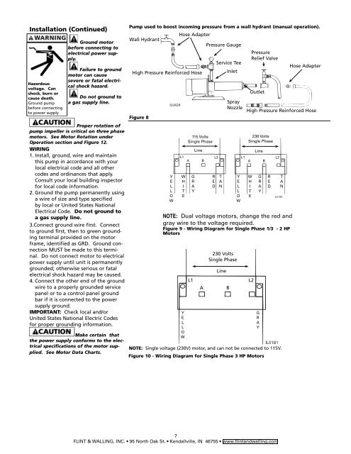
Pump used to boost incoming pressure from a wall hydrant (manual operation).<br />
Wall Hydrant<br />
Figure 8<br />
IL0424<br />
Hose Adapter<br />
High <strong>Pressure</strong> Reinforced Hose<br />
Y<br />
E<br />
L<br />
L<br />
O<br />
W<br />
115 Volts<br />
Single Phase<br />
<strong>Pressure</strong> Gauge<br />
Service Tee<br />
Spray<br />
Nozzle<br />
<strong>Pressure</strong><br />
Relief Valve<br />
Outlet<br />
7<br />
FLINT & WALLING, INC. 95 North Oak St. Kendallville, IN 46755 www.flintandwalling.com<br />
Inlet<br />
230 Volts<br />
Single Phase<br />
Line<br />
L1 L2<br />
A B<br />
Hose Adapter<br />
High <strong>Pressure</strong> Reinforced Hose<br />
230 Volts<br />
Single Phase<br />
Line Line<br />
L1<br />
A B<br />
L2 L1<br />
A B<br />
L2<br />
W<br />
H<br />
I<br />
T<br />
E<br />
G<br />
R<br />
A<br />
Y<br />
R<br />
E<br />
D<br />
T<br />
A<br />
N<br />
IL0180<br />
NOTE: Dual voltage motors, change the red and<br />
gray wire to the voltage required.<br />
Figure 9 - Wiring Diagram for Single Phase 1/3 - 2 HP<br />
Motors<br />
Y<br />
G<br />
E<br />
R<br />
L<br />
A<br />
L<br />
Y<br />
O<br />
W<br />
IL0181<br />
NOTE: Single voltage (230V) motor, and can not be connected to 115V.<br />
Figure 10 - Wiring Diagram for Single Phase 3 HP Motors<br />
Y<br />
E<br />
L<br />
L<br />
O<br />
W<br />
W<br />
H<br />
I<br />
T<br />
E<br />
G<br />
R<br />
A<br />
Y<br />
R<br />
E<br />
D<br />
T<br />
A<br />
N