Pressure Booster Pumps - Pure Aqua Inc
Pressure Booster Pumps - Pure Aqua Inc
Pressure Booster Pumps - Pure Aqua Inc

You also want an ePaper? Increase the reach of your titles
YUMPU automatically turns print PDFs into web optimized ePapers that Google loves.
Installation (Continued)<br />
5.Specific Wiring Procedure (Refer to Figures 9, 10, & 11<br />
and Minimum Wire Size Chart).<br />
a. Select the voltage you are to use, either 115V or 230V<br />
single phase, 230V or 460V three phase.<br />
b. The 1/3, 1/2 and 3/4 HP single phase pumps are factory<br />
connected for 115V at the motor. The 1, 11/2, 2 and 3<br />
HP pumps are factory connected for 230V at the motor.<br />
Three phase models are factory connected for 230V at<br />
the motor.<br />
c. If the motor wiring must be changed to conform to your<br />
specific voltage requirements then the motor, pressure<br />
switch or other controls should be rewired to conform<br />
to one of the wiring diagrams (either 115V or 230V,<br />
single phase; 230V or 460V, three phase). Single phase 3<br />
HP motors are 230V only and cannot be wired for 115V<br />
service.<br />
d. The motor wiring diagrams are Figures 9, 10, & 11 and<br />
also are located on the motor label of the pump.<br />
6. Remove the rear access cover of the motor.<br />
7. Make the wiring change and replace the rear access cover.<br />
!<br />
Replace rear access cover before starting<br />
or operating pump. Failure to do so can result in personal<br />
injury.<br />
IMPORTANT: Do not use an extension cord or splice wires.<br />
Joints should be made in an approved junction box. If the<br />
above information or the following wiring diagrams are confusing,<br />
consult a licensed electrician.<br />
8. All units are not supplied with pressure switches, float<br />
devices, on/off switches, or the like (control devices).<br />
Controls should be wired in at this time, utilizing whatever<br />
instructions come with the controls. All units supplied<br />
with cords, will run whenever cord is plugged into power<br />
and will turn off whenever cord is disconnected from<br />
power.<br />
MOTOR PROTECTION<br />
All single phase motors have built in thermal protection for<br />
all voltages. The overload protects the motor against burnout<br />
from overload of low voltage, high voltage and other<br />
causes. The device is automatic and resets itself once the<br />
temperature has dropped to a safe point. Frequent tripping<br />
of the device indicates trouble in the motor or power lines<br />
and immediate attention is needed.<br />
!<br />
Never examine, make wiring changes or<br />
touch the motor before disconnecting the main electrical<br />
supply switch. The thermal device may have opened the<br />
electrical circuit.<br />
Three phase motors do not have a built in thermal protection.<br />
It is recommended that a properly sized magnetic or<br />
manual starter (both with properly sized heaters) be used<br />
with all three phase motors. Install starters following instructions<br />
of the starter manufacturer. See Motor Rotation under<br />
Operation Section for changing rotation on three phase<br />
motors.<br />
All motors (single and three phase) should be equipped<br />
with a correctly fused disconnect switch to provide protection.<br />
Consult local or United States National Electric Codes<br />
for proper fuse protection based on motor data chart (See<br />
Charts C, D and Wire chart F).<br />
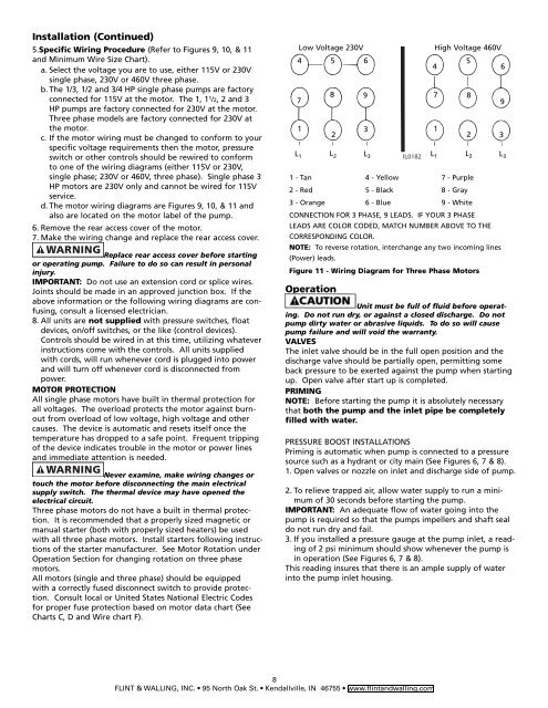
Low Voltage 230V High Voltage 460V<br />
4 5 6<br />
4<br />
5<br />
6<br />
Operation<br />
IL0182<br />
Unit must be full of fluid before operating.<br />
Do not run dry, or against a closed discharge. Do not<br />
pump dirty water or abrasive liquids. To do so will cause<br />
pump failure and will void the warranty.<br />
VALVES<br />
The inlet valve should be in the full open position and the<br />
discharge valve should be partially open, permitting some<br />
back pressure to be exerted against the pump when starting<br />
up. Open valve after start up is completed.<br />
PRIMING<br />
NOTE: Before starting the pump it is absolutely necessary<br />
that both the pump and the inlet pipe be completely<br />
filled with water.<br />
PRESSURE BOOST INSTALLATIONS<br />
Priming is automatic when pump is connected to a pressure<br />
source such as a hydrant or city main (See Figures 6, 7 & 8).<br />
1. Open valves or nozzle on inlet and discharge side of pump.<br />
2. To relieve trapped air, allow water supply to run a minimum<br />
of 30 seconds before starting the pump.<br />
IMPORTANT: An adequate flow of water going into the<br />
pump is required so that the pumps impellers and shaft seal<br />
do not run dry and fail.<br />
3. If you installed a pressure gauge at the pump inlet, a reading<br />
of 2 psi minimum should show whenever the pump is<br />
in operation (See Figures 6, 7 & 8).<br />
This reading insures that there is an ample supply of water<br />
into the pump inlet housing.<br />
8<br />
FLINT & WALLING, INC. 95 North Oak St. Kendallville, IN 46755 www.flintandwalling.com<br />
7<br />
1<br />
8 9<br />
2<br />
3<br />
L 1 L 2 L 3<br />
7 8<br />
1<br />
2<br />
9<br />
3<br />
L 1 L 2 L 3<br />
1 - Tan 4 - Yellow 7 - Purple<br />
2 - Red 5 - Black 8 - Gray<br />
3 - Orange 6 - Blue 9 - White<br />
CONNECTION FOR 3 PHASE, 9 LEADS. IF YOUR 3 PHASE<br />
LEADS ARE COLOR CODED, MATCH NUMBER ABOVE TO THE<br />
CORRESPONDING COLOR.<br />
NOTE: To reverse rotation, interchange any two incoming lines<br />
(Power) leads.<br />
Figure 11 - Wiring Diagram for Three Phase Motors