FP 405-11 - Bermad
FP 405-11 - Bermad
FP 405-11 - Bermad

You also want an ePaper? Increase the reach of your titles
YUMPU automatically turns print PDFs into web optimized ePapers that Google loves.
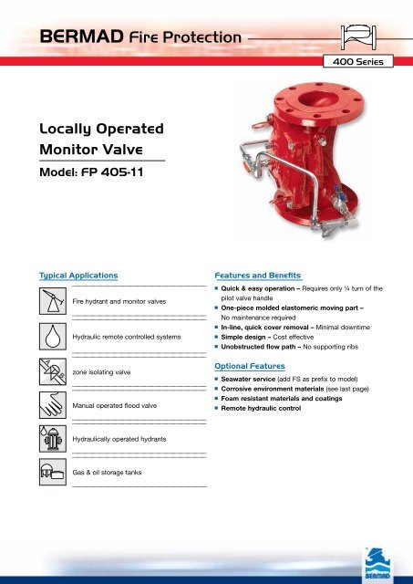
BERMAD Fire Protection<br />
Locally Operated<br />
Monitor Valve<br />
Model: <strong>FP</strong> <strong>405</strong>-<strong>11</strong><br />
Typical Applications Features and Benefits<br />
A B<br />
Fire hydrant and monitor valves<br />
Hydraulic remote controlled systems<br />
zone isolating valve<br />
Manual operated flood valve<br />
Hydraulically operated hydrants<br />
Gas & oil storage tanks<br />
400 Series<br />
■ Quick & easy operation ־ Requires only ¼ turn of the<br />
pilot valve handle<br />
■ One-piece molded elastomeric moving part ־<br />
No maintenance required<br />
■ In-line, quick cover removal ־ Minimal downtime<br />
■ Simple design ־ Cost effective<br />
■ Unobstructed flow path ־ No supporting ribs<br />
Optional Features<br />
■ Seawater service (add FS as prefix to model)<br />
■ Corrosive environment materials (see last page)<br />
■ Foam resistant materials and coatings<br />
■ Remote hydraulic control
BERMAD Fire Protection<br />
Model: <strong>FP</strong> <strong>405</strong>-<strong>11</strong><br />
Operation<br />
400 Series<br />
The BERMAD Model <strong>FP</strong> <strong>405</strong>-<strong>11</strong> is a simply designed, manually operated, on/off valve. It is particularly suited for<br />
monitors and industrial high capacity hydrants.<br />
The Model <strong>FP</strong> <strong>405</strong>-<strong>11</strong> is held closed by line-pressure [1] applied to the control chamber [2] of the valve. The closed<br />
valve prevents the water (or water foam) from passing through the valve, keeping the downstream piping dry.<br />
In the set position, the line pressure is applied to the control chamber of the valve. The pressure holds the main<br />
valve’s diaphragm and plug against the valve seat [3]. Seal is drip tight. The Check Valve [4] traps high pressure peaks<br />
ensuring that the valve remains locked in the closed position to maintain drip tight sealing.<br />
To open, a ¼ turn of the Manual Release Pilot [5] handle releases pressure from the control chamber through the<br />
opened Manual Release Valve. The diaphragm plug is then pushed open by the upstrim force at its bottom, allowing<br />
water to flow into the system.<br />
[1]<br />
Engineer Specifications<br />
[4] [5]<br />
[2]<br />
[3]<br />
Valve Closed (set position) Valve Open (operating condition)<br />
■ The valve shall be a hydraulic controlled, elastomeric type globe valve with a rolling-diaphragm.<br />
■ The valve shall have an unobstructed flow path, with no stem guide or supporting ribs.<br />
■ Valve actuation shall be accomplished by a fully peripherally supported, one-piece balanced rolling-diaphragm,<br />
vulcanized with a rugged radial seal disk. The diaphragm assembly shall be the only moving part.<br />
■ The valve shall have a removable cover for quick in-line service enabling all necessary inspection and servicing.<br />
■ The control trim shall consist of non-corrosive tubing and fittings, Manual Release Pilot, Check Valve and Y strainer.<br />
■ The valve trim shall be supplied as an assembly, pre-assembled and hydraulically tested at an<br />
ISO 9000 and 9001 certified factory.<br />
to drain
BERMAD Fire Protection<br />
Model: <strong>FP</strong> <strong>405</strong>-<strong>11</strong><br />
Local Manually Operated<br />
Monitor Valve Model <strong>FP</strong> <strong>405</strong>-<strong>11</strong><br />
This line pressure powered on/off valve replaces<br />
mechanical valves that often stick after long<br />
periods<br />
in the closed position. This valve is built to react<br />
smoothly and easily following any passage of time,<br />
from either the closed or open position.<br />
System Components<br />
1 - Main Valve, <strong>Bermad</strong> Model <strong>FP</strong>-<strong>405</strong>-<strong>11</strong><br />
2 - Manual Release Pilot<br />
3 - Fire Monitor<br />
2<br />
Note: Graphics are for illustration only<br />
1<br />
3<br />
2<br />
1<br />
400 Series<br />
Remote Controlled Monitor System<br />
(with Foam Concentrate Injection)<br />
Monitors located in hazardous areas should be<br />
operated from a remote panel in order to ensure<br />
their<br />
safe activation under fire conditions.<br />
Applying the <strong>Bermad</strong> Model <strong>FP</strong> 400E-5X to control<br />
Oscillating, Elevated and Pre-cooling spraying<br />
Monitors ensures quick response to any situation<br />
by an easy ¼ turn of the valve remoted pilot handle.<br />
System Components<br />
1 - Main Valve, BERMAD Model 400E-5X<br />
2 - Remote Manual Release Pilot<br />
3 - Remote Fire Monitor<br />
3
BERMAD Fire Protection<br />
Model: <strong>FP</strong> <strong>405</strong>-<strong>11</strong><br />
Technical Data<br />
Dimensions<br />
Size<br />
L 1<br />
L 4<br />
Tw<br />
L 1<br />
L 4<br />
R<br />
Th<br />
400 Series<br />
1½”, 2” 2½” 3” 4” 6” 8” 10”<br />
mm inch mm inch mm inch mm inch mm inch mm inch mm inch<br />
(1) L1 205 81 /16 205 81 /16 257 101 /8 320 125 /8 415 165 /16 500 19<strong>11</strong> /16 605 2313 /16<br />
(2) L4 205 81 /16 N/A N/A 250 913 /16 320 125 /8 N/A N/A 500 19<strong>11</strong> /16 N/A N/A<br />
Tw 318 12 1 /2 329 12 15 /16 340 13 3 /8 352 13 13 /16 393 15 1 /2 423 16 5 /8 443 17 7 /16<br />
Th 232 9 1 /8 244 9 5 /8 265 10 3 /8 285 <strong>11</strong> 1 /4 360 14 3 /16 415 16 5 /16 413 16 1 /4<br />
R 78 3 1 /16 89 3 1 /2 100 3 15 /16 <strong>11</strong>2 4 7 /16 140 5 1 /2 170 6 <strong>11</strong> /16 203 8<br />
Notes:<br />
1. L 1 is for flanged ANSI #150 and ISO PN16.<br />
2. L 4 is for grooved end connections (Ductile Iron Only).<br />
Connection Standard<br />
• Flanged: ANSI B16.42 (Ductile Iron),<br />
B16.5 (Steel & Stainless Steel),<br />
B16.24 (Bronze)<br />
• ISO PN16<br />
• Grooved: ANSI/AWWA C606 for 2, 3, 4, 6 & 8”<br />
Manufacturers Standard Materials<br />
Main valve body and cover<br />
• Ductile Iron ASTM A-536<br />
Main valve internals<br />
• Stainless Steel & elastomer<br />
Control Trim System<br />
• Brass control components/accessories<br />
• Forged Brass fittings & Copper tubing<br />
Elastomers<br />
• Nylon fabric reinforced polyisoprene NR<br />
Coating<br />
• Electrostatic Power Coating Polyester,<br />
Red (RAL 3002)<br />
Water Temperature<br />
• 0.5 – 50°C (33 – 122°F)<br />
Available Sizes<br />
• 1½, 2, 2½, 3, 4, 6, 8, 10 & 12"<br />
Pressure Rating<br />
• Max. working pressure: 235 psi (16 bar)<br />
Optional Materials<br />
Main valve body<br />
• Carbon Steel ASTM A-216-WCB<br />
• Stainless Steel 316<br />
• Ni-Al-Bronze ASTM B-148<br />
Control Trim<br />
• Stainless Steel 316<br />
• Monel) and Al-Bronze<br />
• Hastalloy C-276<br />
Elastomers<br />
• NBR<br />
• EPDM<br />
Coating<br />
• High Build Epoxy Fusion-Bonded<br />
with UV Protection, Anti-Corrosion<br />
bermadfire@bermad.com • www.bermad.com<br />
The information herein is subject to change without notice. BERMAD shall not be held<br />
liable for any errors. All rights reserved. © Copyright by BERMAD. PE4PE-5<strong>11</strong> <strong>11</strong><br />
3. Provide adequate space around valve for maintenance.<br />
4. Data is for envelope dimensions, specific component positioning may vary.