
Create successful ePaper yourself
Turn your PDF publications into a flip-book with our unique Google optimized e-Paper software.
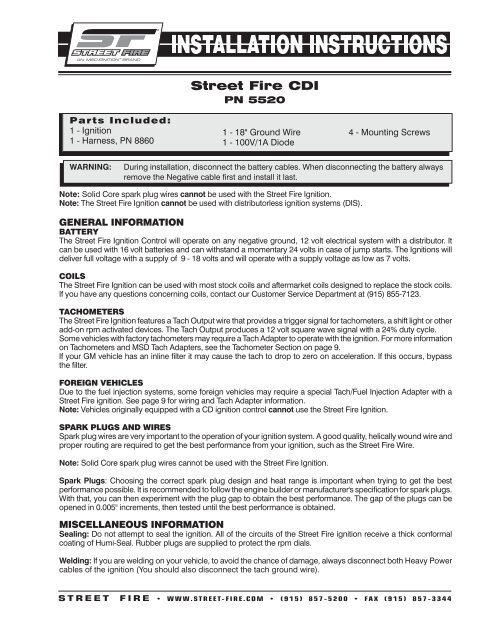
Parts Included:<br />
1 - <strong>Ignition</strong><br />
1 - Harness, PN 8860<br />
®<br />
<strong>Street</strong> <strong>Fire</strong> <strong>CDI</strong><br />
PN 5520<br />
1 - 18" Ground Wire<br />
1 - 100V/1A Diode<br />
WARNING: During installation, disconnect the battery cables. When disconnecting the battery always<br />
remove the Negative cable first and install it last.<br />
Note: Solid Core spark plug wires cannot be used with the <strong>Street</strong> <strong>Fire</strong> <strong>Ignition</strong>.<br />
Note: The <strong>Street</strong> <strong>Fire</strong> <strong>Ignition</strong> cannot be used with distributorless ignition systems (DIS).<br />
GENERAL INFORMATION<br />
BATTERY<br />
The <strong>Street</strong> <strong>Fire</strong> <strong>Ignition</strong> Control will operate on any negative ground, 12 volt electrical system with a distributor. It<br />
can be used with 16 volt batteries and can withstand a momentary 24 volts in case of jump starts. The <strong>Ignition</strong>s will<br />
deliver full voltage with a supply of 9 - 18 volts and will operate with a supply voltage as low as 7 volts.<br />
COILS<br />
The <strong>Street</strong> <strong>Fire</strong> <strong>Ignition</strong> can be used with most stock coils and aftermarket coils designed to replace the stock coils.<br />
If you have any questions concerning coils, contact our Customer Service Department at (915) 855-7123.<br />
TACHOMETERS<br />
The <strong>Street</strong> <strong>Fire</strong> <strong>Ignition</strong> features a Tach Output wire that provides a trigger signal for tachometers, a shift light or other<br />
add-on rpm activated devices. The Tach Output produces a 12 volt square wave signal with a 24% duty cycle.<br />
Some vehicles with factory tachometers may require a Tach Adapter to operate with the ignition. For more information<br />
on Tachometers and <strong>MSD</strong> Tach Adapters, see the Tachometer Section on page 9.<br />
If your GM vehicle has an inline filter it may cause the tach to drop to zero on acceleration. If this occurs, bypass<br />
the filter.<br />
FOREIGN VEHICLES<br />
Due to the fuel injection systems, some foreign vehicles may require a special Tach/Fuel Injection Adapter with a<br />
<strong>Street</strong> <strong>Fire</strong> ignition. See page 9 for wiring and Tach Adapter information.<br />
Note: Vehicles originally equipped with a CD ignition control cannot use the <strong>Street</strong> <strong>Fire</strong> <strong>Ignition</strong>.<br />
SPARK PLUGS AND WIRES<br />
Spark plug wires are very important to the operation of your ignition system. A good quality, helically wound wire and<br />
proper routing are required to get the best performance from your ignition, such as the <strong>Street</strong> <strong>Fire</strong> Wire.<br />
Note: Solid Core spark plug wires cannot be used with the <strong>Street</strong> <strong>Fire</strong> <strong>Ignition</strong>.<br />
4 - Mounting Screws<br />
Spark Plugs: Choosing the correct spark plug design and heat range is important when trying to get the best<br />
performance possible. It is recommended to follow the engine builder or manufacturer's specification for spark plugs.<br />
With that, you can then experiment with the plug gap to obtain the best performance. The gap of the plugs can be<br />
opened in 0.005" increments, then tested until the best performance is obtained.<br />
MISCELLANEOUS INFORMATION<br />
Sealing: Do not attempt to seal the ignition. All of the circuits of the <strong>Street</strong> <strong>Fire</strong> ignition receive a thick conformal<br />
coating of Humi-Seal. Rubber plugs are supplied to protect the rpm dials.<br />
Welding: If you are welding on your vehicle, to avoid the chance of damage, always disconnect both Heavy Power<br />
cables of the ignition (You should also disconnect the tach ground wire).<br />
S T R E E T F I R E • www.STREET- FIRE.com • (915) 857-5200 • FAX (915) 857-3344
INSTALLATION INSTRUCTIONS<br />
MOUNTING<br />
The <strong>Street</strong> <strong>Fire</strong> <strong>Ignition</strong> can be mounted in most positions, except directly upside down (if upside down, moisture or<br />
water cannot escape). It can be mounted in the engine compartment as long as it is away from direct engine heat<br />
sources. It is not recommended to mount the unit in an enclosed area such as the glove box.<br />
When you find a suitable location to mount the unit, make sure the wires of the ignition reach their connections.<br />
Hold the <strong>Ignition</strong> in place and mark the location of the mounting holes. Use an 1/8" drill bit to drill the holes. Use the<br />
supplied self tapping screws to mount the box.<br />
CYLINDER SELECT<br />
The Rev Limiter that is built into the ignition is programmed for operation<br />
on a 8-cylinder engine. If you are installing one of these units on a 4 or<br />
6-cylinder even-fire engine, the cylinder count must be selected. This is<br />
easily achieved through the cylinder select wire loops on the side of the<br />
ignition. To program the unit cut the loops as shown in Figure 1.<br />
LED<br />
There is a diagnostic LED next to the rpm dials. The LED will blink with<br />
each trigger signal. It will appear On when the engine is running. If the<br />
input voltage drops below 9 volts it will flash at idle speed.<br />
WIRING<br />
Wire Length: All of the wires of the ignition may be shortened as long as<br />
quality connectors are used or soldered in place. To lengthen the wires,<br />
use one size bigger gauge wire (10 gauge for the power leads and 16<br />
gauge for the other wires) with the proper connections.<br />
Grounds: A poor ground connection can cause many frustrating problems.<br />
When a wire is specified to go to ground, it should be connected to the battery negative terminal, engine block or<br />
chassis. There should always be a ground strap between the engine and the chassis. Always securely connect the<br />
ground wire to a clean, paint free metal surface.<br />
WIRE FUNCTIONS<br />
PoWeR LeAdS<br />
HeAvy Red<br />
HeAvy BLAck<br />
Red<br />
oRANGe<br />
BLAck<br />
GRAy<br />
TRIGGeR<br />
WIReS<br />
WHITe<br />
vIoLeT ANd<br />
GReeN (Magnetic<br />
Pickup connector)<br />
These are the two heavy gauge wires (14 gauge) and are responsible for getting direct battery<br />
voltage to the <strong>Ignition</strong>.<br />
This wire connects directly to the battery positive (+) terminal or to a positive battery junction or<br />
the positive side of the starter solenoid.<br />
Note: Never connect to the alternator.<br />
This wire connects to a good ground, either at the battery negative (-) terminal or to the<br />
engine.<br />
Connects to a switched 12 volt source. Such as the ignition key or switch.<br />
Connects to the positive (+) terminal of the coil.<br />
This is the only wire that makes electrical contact with the coil positive terminal.<br />
Connects to the negative (-) terminal of the coil.<br />
This is the only wire that makes electrical contact with the coil negative terminal.<br />
Tach output wire. Connect to the tachometer or other rpm device.<br />
CYLINDER SELECT<br />
LOOPS<br />
Figure 1 Selecting the number of<br />
Cylinders.<br />
There are two circuits that can be used to trigger the <strong>Street</strong> <strong>Fire</strong> <strong>Ignition</strong>; a Points circuit (White<br />
wire) and a Magnetic Pickup circuit (Violet and Green wires). The two circuits will never be used<br />
together.<br />
This wire is used to connect to the points or electronic ignition amplifier output .<br />
These wires are routed together in one harness to form the Magnetic Pickup connector. The<br />
connector plugs directly into an <strong>MSD</strong> Distributor. It will also connect to factory magnetic pickups<br />
or other aftermarket pickups. The Violet wire is positive (+) and the Green is negative (-). When<br />
these wires are used, the White wire is not.<br />
S T R E E T F I R E • www.STREET- FIRE.com • (915) 857-5200 • FAX (915) 857-3344
INSTALLATION INSTRUCTIONS<br />
The chart in Figure 2 shows the polarity of other common<br />
magnetic pickups.<br />
Ballast Resistor: If your vehicle has a ballast resistor in line with<br />
the coil wiring, it is recommended to bypass it.<br />
ROUTING WIRES<br />
The <strong>Street</strong> <strong>Fire</strong> wires should be routed away from direct heat<br />
sources such as exhaust manifolds and headers and any sharp<br />
edges. The trigger wires should be routed separate from the<br />
other wires and spark plug wires. It is best if they are routed along<br />
a ground plane such as the block or firewall which creates an<br />
electrical shield. The magnetic pickup wires should always be<br />
routed separately and should be twisted together to help reduce<br />
extraneous interference.<br />
REV LIMITER<br />
The <strong>Street</strong> <strong>Fire</strong> <strong>Ignition</strong> features an adjustable rev limiter. This feature will protect<br />
your engine from overrev damge in the event of driveline failure or a missed<br />
gear. The rev limit is adjustable from 2,000 - 9,900 rpm in 100 rpm increments<br />
(Figure 3).<br />
PRESTART CHECK LIST<br />
• The only wires connected to the coil terminals are the <strong>Street</strong> <strong>Fire</strong> Orange to<br />
coil positive and Black to coil negative.<br />
• The small Red wire of the <strong>CDI</strong> is connected to a switched 12 volt source.<br />
• If running a 4 or 6-cylinder engine the cylinder select must be modified.<br />
• The power leads are connected directly to the battery positive and negative<br />
terminals.<br />
common Mag Pickup Wires<br />
colors<br />
Mag+ Mag-<br />
MSd distributor org/Blk vio/Blk<br />
MSd crank Trigger violet Green<br />
Ford orange violet<br />
Accel 46/48000 Series org/Blk vio/Blk<br />
Accel 51/61000 Series Red Black<br />
chrysler org/Wht Black<br />
Mallory org/Blk vio/Blk<br />
<strong>Street</strong> <strong>Fire</strong> cdI violet Green<br />
Figure 2 Common Mag Pickup Wires.<br />
WARNING: The <strong>Street</strong> <strong>Fire</strong> <strong>CDI</strong> is a capacitive discharge ignition. High voltage is present at the coil primary<br />
terminals. Do not touch the coil or connect test equipment to the terminals.<br />
STREET FIRE SYSTEMS Installing to Points/Amplifier Style <strong>Ignition</strong>.<br />
NOTE: On dual point setups, it is recommended<br />
to remove the trailing set of points.<br />
NOTE: Ballast Resistor is not necessary.<br />
TO<br />
TACH<br />
®<br />
<strong>CDI</strong> MULTI-SPARK<br />
IGNITION<br />
PN 5520<br />
WWW.STREET-FIRE.COM<br />
GRAY<br />
SMALL<br />
RED<br />
S T R E E T F I R E • www.STREET- FIRE.com • (915) 857-5200 • FAX (915) 857-3344<br />
WHITE<br />
ORANGE<br />
BLACK<br />
COIL<br />
CYLINDER SELECT<br />
LOOPS<br />
Figure 3 Adjusting the Rev Limiter.<br />
NOTE: Remove the coil<br />
terminal wires.The negative<br />
wire connects to the <strong>Street</strong><br />
<strong>Fire</strong> White.The positive wire<br />
connects to the <strong>Street</strong> <strong>Fire</strong><br />
Red.The <strong>Street</strong> <strong>Fire</strong> Orange<br />
connects to the coil positive<br />
terminal, Black connects to<br />
the coil negative terminal.
<strong>MSD</strong> SYSTEMS Installing to an <strong>MSD</strong> Distributor.<br />
NOTE: SEE FIGURE 2 FOR COMMON MAGNETIC PICKUPS.<br />
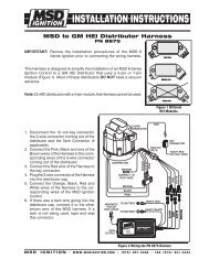
GM IGNITIONS Wiring with an <strong>MSD</strong> Wiring Harness.<br />
TO<br />
TACH<br />
<strong>CDI</strong> MULTI-SPARK<br />
IGNITION<br />
PN 5520<br />
WWW.STREET-FIRE.COM<br />
TO<br />
TACH<br />
®<br />
®<br />
<strong>CDI</strong> MULTI-SPARK<br />
IGNITION<br />
PN 5520<br />
WWW.STREET-FIRE.COM<br />
GRAY<br />
GRAY<br />
SMALL<br />
RED<br />
WHITE<br />
SMALL RED<br />
INSTALLATION INSTRUCTIONS<br />
WHITE (NOT USED)<br />
ORANGE<br />
GM IGNITIONS Wiring a Dual Connector Coil.<br />
BOTH PINKS<br />
TO<br />
TACH<br />
®<br />
<strong>CDI</strong> MULTI-SPARK<br />
IGNITION<br />
PN 5520<br />
WWW.STREET-FIRE.COM<br />
GRAY<br />
RED<br />
RED<br />
SMALL<br />
RED<br />
WHITE<br />
ORANGE<br />
BLACK<br />
BLACK<br />
DISTRIBUTOR<br />
WITH<br />
MAGNETIC PICKUP<br />
NOTE: For a direct plug-in, use <strong>MSD</strong><br />
Harness PN 8876.<br />
NOTE: Cut and splice the two Pink wires<br />
(coil positive) together and connect<br />
to Orange wire of the ignition. Cut<br />
and splice the twoWhite wires (coil<br />
negative) together and connect<br />
to the White of the ignition. If the<br />
vehicle is not equipped with a<br />
factory tach, there will only be one<br />
White wire.<br />
Harness PN 8876 - Dual Connector Coil.<br />
Harness PN 8877 - 1996-on GM Vehicles.<br />
S T R E E T F I R E • www.STREET- FIRE.com • (915) 857-5200 • FAX (915) 857-3344
INSTALLATION INSTRUCTIONS<br />
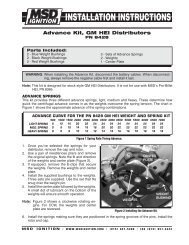
GM IGNITIONS GM Large Cap HEI Distributors<br />
There are three different large cap HEI distributors. To identify which of the following diagrams fit your specific application, remove the distributor<br />
cap and rotor and locate the ignition module at the base of the distributor. Count the number of terminals on both ends of the module and follow<br />
the corresponding diagram. GM used 4, 5 and 7-pin modules in these distributors.<br />
NOTE: Some 5-pin models may experience a hesitation or stall on deceleration. If this occurs, contact <strong>MSD</strong> Tech Line for the required bolt-in<br />
diode to correct the problem. <strong>MSD</strong> Tech Line (915) 855-7123.<br />
GM IGNITIONS Wiring an HEI 4-pin Module (Magnetic Pickup Trigger).<br />
TO<br />
TACH<br />
®<br />
<strong>CDI</strong> MULTI-SPARK<br />
IGNITION<br />
PN 5520<br />
WWW.STREET-FIRE.COM<br />
GRAY<br />
SMALL RED<br />
NOTE: The GM <strong>Ignition</strong> Module is removed<br />
and replaced with the supplied PN<br />
8861 Wire Harness.<br />
S T R E E T F I R E • www.STREET- FIRE.com • (915) 857-5200 • FAX (915) 857-3344
GM IGNITIONS Wiring an HEI 5 or 7-pin Module (Amplifier Trigger).<br />
NOTE: Some 5-pin models may experience a<br />
hesitation or stall on deceleration. If this<br />
occurs, contact <strong>MSD</strong>Tech Line for the required<br />
bolt-in diode to correct the problem. <strong>MSD</strong> Tech<br />
Line (915) 855-7123.<br />
FORD IGNITIONS Wiring a Ford DuraSpark using White Wire Trigger.<br />
TO<br />
TACH<br />
<strong>CDI</strong> MULTI-SPARK<br />
IGNITION<br />
PN 5520<br />
WWW.STREET-FIRE.COM<br />
TO<br />
TACH<br />
®<br />
®<br />
<strong>CDI</strong> MULTI-SPARK<br />
IGNITION<br />
PN 5520<br />
WWW.STREET-FIRE.COM<br />
GRAY<br />
GRAY<br />
INSTALLATION INSTRUCTIONS<br />
S T R E E T F I R E • www.STREET- FIRE.com • (915) 857-5200 • FAX (915) 857-3344<br />
SMALL RED<br />
COIL
INSTALLATION INSTRUCTIONS<br />
FORD IGNITIONS Wiring a Ford DuraSpark using Magnetic Pickup Trigger.<br />
INDICATES CONNECTION<br />
MAGNETIC PICKUP<br />
CONNECTOR<br />
TO<br />
TACH<br />
®<br />
<strong>CDI</strong> MULTI-SPARK<br />
IGNITION<br />
PN 5520<br />
WWW.STREET-FIRE.COM<br />
GRAY<br />
FORD<br />
DISTRIBUTOR<br />
GREEN<br />
PN 8860<br />
HARNESS<br />
BLACK<br />
(NOT USED)<br />
+<br />
VIOLET<br />
DISTRIBUTOR<br />
CONNECTOR-<br />
DISCONNECT FROM<br />
ORIGINAL HARNESS<br />
+<br />
ORANGE<br />
VIOLET<br />
WHITE<br />
(NOT USED)<br />
COVER W/TAPE<br />
S T R E E T F I R E • www.STREET- FIRE.com • (915) 857-5200 • FAX (915) 857-3344<br />
TACH<br />
C+<br />
NOT USED<br />
FORD IGNITIONS Wiring a Ford TFI with Harness, PN 8874.<br />
TO<br />
TACH<br />
®<br />
<strong>CDI</strong> MULTI-SPARK<br />
IGNITION<br />
PN 5520<br />
WWW.STREET-FIRE.COM<br />
GRAY<br />
WHITE<br />
SMALL RED<br />
FORD IGNITIONS Wiring a Ford TFI (without Harness).<br />
TO<br />
TACH<br />
<strong>CDI</strong> MULTI-SPARK<br />
IGNITION<br />
PN 5520<br />
WWW.STREET-FIRE.COM<br />
GRAY<br />
RED<br />
WHITE<br />
® SMALL<br />
NoTe: Use <strong>MSD</strong> Harness, PN 8874.<br />
BLACK<br />
SMALL RED<br />
ORANGE<br />
BLACK<br />
+<br />
ORANGE<br />
COIL<br />
+
INSTALLATION INSTRUCTIONS<br />
CHRYSLER IGNITIONS Wiring a Chrysler Electronic <strong>Ignition</strong> using Magnetic Pickup Trigger.<br />
TO<br />
TACH<br />
®<br />
<strong>CDI</strong> MULTI-SPARK<br />
IGNITION<br />
PN 5520<br />
WWW.STREET-FIRE.COM<br />
GRAY<br />
MAGNETIC<br />
PICKUP<br />
CONNECTOR<br />
WHITE<br />
(NOT USED)<br />
<strong>MSD</strong> SYSTEMS Installing to an <strong>MSD</strong> Distributor PN 8360.<br />
TO<br />
TACH<br />
®<br />
<strong>CDI</strong> MULTI-SPARK<br />
IGNITION<br />
PN 5520<br />
WWW.STREET-FIRE.COM<br />
AFTERMARKET COMPONENTS Wiring to a Pertronix Ignitor Kit.<br />
TO<br />
TACH<br />
<strong>CDI</strong> MULTI-SPARK<br />
IGNITION<br />
PN 5520<br />
WWW.STREET-FIRE.COM<br />
GRAY<br />
®<br />
DISTRIBUTOR<br />
WITH<br />
PERTRONIX<br />
GRAY<br />
BLACK<br />
SMALL RED<br />
SMALL RED<br />
S T R E E T F I R E • www.STREET- FIRE.com • (915) 857-5200 • FAX (915) 857-3344<br />
RED<br />
ORANGE<br />
BLACK<br />
COIL<br />
NOTE: The ignition module of the PN 8360<br />
still triggers the <strong>Street</strong> <strong>Fire</strong> <strong>Ignition</strong>.<br />
COIL
INSTALLATION INSTRUCTIONS<br />
AFTERMARKET COMPONENTS Wiring a Mallory Unilite or 9000 Series using Points Trigger.<br />
TO<br />
TACH<br />
®<br />
<strong>CDI</strong> MULTI-SPARK<br />
IGNITION<br />
PN 5520<br />
WWW.STREET-FIRE.COM<br />
GRAY<br />
TROUBLESHOOTING<br />
Every <strong>Street</strong> <strong>Fire</strong> <strong>Ignition</strong> undergoes numerous quality control checks including a four hour burn-in test. If you<br />
experience a problem with your ignition, our research has shown that the majority of problems are due to improper<br />
installation or poor connections.<br />
The Troubleshooting section has several checks and tests you can perform to ensure proper installation and operation<br />
of the <strong>Street</strong> <strong>Fire</strong> <strong>Ignition</strong>. If you have any questions, call our Customer Support Department at (915) 855-7123, 7<br />
- 6 mountain time.<br />
TACH/FUEL ADAPTERS<br />
If your tachometer does not operate correctly or if you experience a no-run situation with your foreign vehicle you probably<br />
need a Tach Adapter from <strong>MSD</strong> <strong>Ignition</strong>. The chart below lists common tachometers and if an Adapter is necessary.<br />
Tachometer Compatibility List<br />
AFTERMARKET TACHOMETER WHITE WIRE TRIGGER MAGNETIC TRIGGER CONNECTOR<br />
AUTOGAGE 8910 8920<br />
AUTOMETER NONE NONE<br />
FORD MOTORSPORTS NONE NONE<br />
MALLORY NONE NONE<br />
MOROSO NONE NONE<br />
STEWART (voltage triggered) 8910 8920<br />
S.W. & BI TORX NONE NONE<br />
SUN 8910 8920<br />
VDO 8910 8920<br />
AMC (JEEP) 8910 8920<br />
CHRYSLER 8910 8920<br />
FORD (voltage triggered) 8910 8920<br />
GENERAL MOTORS Bypass In-Line Filter Bypass In-line filter<br />
IMPORTS 8910 8920<br />
TOYOTA 8910EIS<br />
Note: On the list above, the trigger wire on tachometers that are marked NONE may be connected to the<br />
Tach Output wire on the <strong>Street</strong> <strong>Fire</strong> <strong>Ignition</strong>.<br />
S T R E E T F I R E • www.STREET- FIRE.com • (915) 857-5200 • FAX (915) 857-3344<br />
COIL
10 INSTALLATION INSTRUCTIONS<br />
NO-RUN ON FOREIGN VEHICLES<br />
Some foreign vehicles with fuel injection systems may require an <strong>MSD</strong> Tach/Fuel Injection Adapter to run with the<br />
<strong>Street</strong> <strong>Fire</strong> <strong>Ignition</strong>. This is because many of these systems use the same trigger source to operate the <strong>CDI</strong>, the<br />
tachometer and the fuel injection. This results in a voltage signal that is too low to accurately trigger the fuel injection.<br />
To fix this, an <strong>MSD</strong> Tach Adapter, PN 8910, will remedy the problem on the majority of vehicles. If the PN 8910 does<br />
not fix the problem, the PN 8910-EIS will be required.<br />
Note: Toyotas and Ford Probes will require the PN 8910-EIS Adapter.<br />
INOPERATIVE TACHOMETERS<br />
If your tachometer fails to operate with the <strong>CDI</strong> installed you may need a Tach Adapter from <strong>MSD</strong> <strong>Ignition</strong>. Before<br />
getting an Adapter, try connecting your tachometer trigger wire to the Gray Wire. This output produces a 12 volt, square<br />
wave (see page 1). If the tach still does not operate, you will need a Tach Adapter. There are two Tach Adapters:<br />
PN 8920: If you are using the Magnetic Pickup connector (Green<br />
and Violet wires) to trigger the <strong>CDI</strong>, you will need the<br />
PN 8920.<br />
PN 8910: If your tachometer was triggered from the coil negative<br />
terminal (voltage trigger) and you are using the White<br />
wire to trigger the cdi you will need the PN 8910.<br />
BALLAST RESISTOR<br />
If you have a current trigger tach (originally coil positive) and<br />
use the White wire of the <strong>CDI</strong>, you can purchase a Chrysler Dual<br />
Ballast Resistor (used from 1973 - 1976) and wire it as shown in<br />
Figure 4.<br />
SWITCHED 12V<br />
(original coil+ wire from tach)<br />
STREET FIRE<br />
RED<br />
CHRYSLER DUAL<br />
BALLAST RESISTOR<br />
FROM POINTS<br />
OR AMPLIFIER<br />
STREET FIRE<br />
WHITE<br />
Figure 4 Wiring the Dual Ballast Resistor.<br />
ENGINE RUN-ON<br />
If your engine continues to run even when the ignition is turned Off you are experiencing engine Run-On. This<br />
usually only occurs on older vehicles with an external voltage regulator. Because the <strong>CDI</strong> receives power directly<br />
from the battery, it does not require much current to keep the unit energized. If you are experiencing Run-On, it is<br />
due to a small amount of voltage going through the charging lamp indicator and feeding the small Red wire even<br />
if the key is turned off.<br />
early Ford and GM: To solve the Run-On problem, a Diode is supplied in the parts bag. By installing this Diode<br />
in-line of the wire that goes to the Charging indicator, the voltage is kept from entering the <strong>CDI</strong>. Figure 5 shows the<br />
proper installation for early Ford and GM vehicles.<br />
Note: Diodes are used to allow voltage to flow only one way. Make sure the Diode is installed facing the proper<br />
direction (as shown in Figure 5).<br />
Ford: Install the Diode in-line to the wire going to the #1 terminal.<br />
GM: Install the Diode in-line to the wire going to terminal #4.<br />
GM 1973 - 1983 with delcotron Alternators<br />
GM Delcotron Alternators use an internal voltage regulator. Install the Diode in-line on the smallest wire exiting the<br />
alternator (Figure 5). It is usually a Brown wire.<br />
S T R E E T F I R E • www.STREET- FIRE.com • (915) 857-5200 • FAX (915) 857-3344
INSTALLATION INSTRUCTIONS 11<br />
EARLY GM VEHICLES ATTACH DIODE TO TERMINAL "4"<br />
FORD VEHICLES<br />
ATTACH DIODE TO<br />
TERMINAL "1"<br />
1 2 3 4<br />
OR<br />
DELCOTRON<br />
ALTERNATOR<br />
Most other applications: On other applications<br />
where engine Run-On is experienced, a Resistor<br />
can be put in-line to the <strong>Street</strong> <strong>Fire</strong>'s small Red<br />
wire (Figure 6). This resistor will keep voltage from<br />
leaking through to the <strong>Street</strong> <strong>Fire</strong> unit.<br />
SPLICE HERE<br />
1A-400V DIODE<br />
WIRE LOOM<br />
TO CHARGING<br />
LIGHT<br />
Figure 5 Installing the Diode to fix Run-On.<br />
STREET FIRE<br />
GM 2-WIRE ALTERNATORS<br />
SMALLER OF THE 2-WIRES<br />
S T R E E T F I R E • www.STREET- FIRE.com • (915) 857-5200 • FAX (915) 857-3344<br />
DIODE<br />
Figure 6 Wiring the Dual Ballast Resistor for Run-On.<br />
MISSES AND INTERMITTENT PROBLEMS<br />
Experience at the races has shown that if your engine is experiencing a miss or hesitation at higher rpm, it is usually<br />
not directly ignition. Most probable causes include a coil or plug wire failure, arcing from the cap or boot plug to<br />
ground or spark ionization inside the cap. Several items to inspect are:<br />
• Always inspect the plug wires at the cap and at the plug for a tight connection and visually inspect for cuts,<br />
abrasions or burns.<br />
• Inspect the Primary Coil Wire connections. Because the <strong>Street</strong> <strong>Fire</strong> is a Capacitive Discharge<br />
ignition and it receives a direct 12 volt source from the battery, there will not be any voltage<br />
at the Coil Positive (+) terminal even with the key turned On. During cranking or while the engine is running, very<br />
high voltage will be present and no test equipment should be connected.<br />
WARNING: Do not touch the coil terminals during cranking or while the engine is running.<br />
• Make sure that the battery is fully charged and the connections are clean and tight. If you are not running an alternator<br />
this is an imperative check. If the battery voltage falls below 10 volts during a race, the <strong>CDI</strong> output voltage will drop.<br />
• Is the engine running lean? Inspect the spark plugs and complete fuel system.<br />
• Inspect all wiring connections for corrosion or damage. Remember to always use proper connections followed<br />
by soldering and seal the connections completely.<br />
If everything checks positive, use the following procedure to test the ignition for spark. <strong>MSD</strong> also offers an <strong>Ignition</strong><br />
Tester, PN 8998. This tool allows you to check your complete ignition system while it is in the car as well as the<br />
operation of rpm limits, activated switches and shift lights.
CHECKING FOR SPARK<br />
If triggering the ignition with the White wire:<br />
®<br />
1 Make sure the ignition switch is in the "Off" position.<br />
2. Remove the coil wire from the distributor cap and set the terminal<br />
approximately 1/2" from ground.<br />
3. Disconnect the White wire from the distributor's points or ignition<br />
amplifier.<br />
4. Turn the ignition to the On position. Do not crank the engine.<br />
5. Tap the White wire to ground several times. Each time you pull<br />
the wire from ground, a spark should jump from the coil wire to<br />
ground (the LED should also blink). If spark is present, the ignition<br />
is working properly. If there is no spark skip to step 6.<br />
If triggering with the Magnetic Pickup:<br />
1. Make sure the ignition switch is in the "Off" position.<br />
2. Remove the coil wire from the distributor cap and set the terminal<br />
approximately 1/2" from ground.<br />
3. Disconnect the magnetic pickup wires from the distributor.<br />
4. Turn the ignition to the On position. Do not crank the engine.<br />
5. With a small jumper wire, short the magnetic pickup Green and Violet<br />
wires together several times. Each time you break this short, a spark<br />
should jump from the coil wire to ground (the LED should also blink). If<br />
spark is present, the ignition is working properly. If there is no spark skip<br />
to step 6.<br />
<strong>CDI</strong> MULTI-SPARK<br />
IGNITION<br />
PN 5520<br />
WWW.STREET-FIRE.COM<br />
Figure 7 Checking for Spark with the White Wire.<br />
6. If there is no spark:<br />
A. Inspect all of the wiring.<br />
B. Substitute another coil and repeat the test. If there is now spark, the coil is at fault.<br />
C. If there is still no spark, check to make sure there is 12 volts on the small Red wire from the <strong>Street</strong> <strong>Fire</strong> <strong>Ignition</strong><br />
when the key is in the On position. If 12 volts is not present, find another switched 12 volt source and repeat<br />
the test.<br />
D. If, after following the test procedures and inspecting all of the wiring, there is still no spark, the <strong>Street</strong> <strong>Fire</strong><br />
<strong>Ignition</strong> is in need of repair. See the Warranty and Service section for information.<br />
Service<br />
In case of malfunction, this <strong>MSD</strong> component will be repaired free of charge according to the terms of the warranty. When<br />
returning <strong>MSD</strong> components for warranty service, Proof of Purchase must be supplied for verification. After the warranty<br />
period has expired, repair service is based on a minimum and maximum fee.<br />
All returns must have a Return Material Authorization (RMA) number issued to them<br />
before being returned. To obtain an RMA number please contact <strong>MSD</strong> Customer Service at 1 (888) <strong>MSD</strong>-7859<br />
or visit our website at www.msdignition.com/rma to automatically obtain a number and shipping information.<br />
When returning the unit for repair, leave all wires at the length in which you have them installed. Be sure to include a detailed<br />
account of any problems experienced, and what components and accessories are installed on the vehicle. The repaired<br />
unit will be returned as soon as possible using Ground shipping methods (ground shipping is covered by warranty). For<br />
more information, call <strong>MSD</strong> <strong>Ignition</strong> at (915) 855-7123. <strong>MSD</strong> technicians are available from 7:00 a.m. to 6:00 p.m. Monday<br />
- Friday (mountain time).<br />
Limited Warranty<br />
<strong>MSD</strong> IGNITION warrants this product to be free from defects in material and workmanship under its intended normal use*, when properly<br />
installed and purchased from an authorized <strong>MSD</strong> dealer, for a period of one year from the date of the original purchase. This warranty is<br />
void for any products purchased through auction websites. If found to be defective as mentioned above, it will be repaired or replaced at<br />
the option of <strong>MSD</strong> <strong>Ignition</strong>. Any item that is covered under this warranty will be returned free of charge using Ground shipping methods.<br />
This shall constitute the sole remedy of the purchaser and the sole liability of <strong>MSD</strong> <strong>Ignition</strong>. To the extent permitted by law, the foregoing is<br />
exclusive and in lieu of all other warranties or representation whether expressed or implied, including any implied warranty of merchantability<br />
or fitness. In no event shall <strong>MSD</strong> <strong>Ignition</strong> or its suppliers be liable for special or consequential damages.<br />
*Intended normal use means that this item is being used as was originally intended and for the original application as sold by <strong>MSD</strong><br />
<strong>Ignition</strong>. Any modifications to this item or if it is used on an application other than what <strong>MSD</strong> <strong>Ignition</strong> markets the product, the warranty will<br />
be void. It is the sole responsibility of the customer to determine that this item will work for the application they are intending. <strong>MSD</strong> <strong>Ignition</strong><br />
will accept no liability for custom applications.<br />
S T R E E T F I R E • www.mSdIgnITIon.com • (915) 857-5200 • FAX (915) 857-3344<br />
© 2007 Autotronic Controls Corporation<br />
FRM28899 Created 11/07 Printed in U.S.A.<br />
®<br />
WHITE WIRE TRIGGER<br />
MAGNETIC PICKUP TRIGGER<br />
®<br />
<strong>CDI</strong> MULTI-SPARK<br />
IGNITION<br />
PN 5520<br />
WWW.STREET-FIRE.COM<br />
GREEN<br />
JUMPER<br />
WIRE<br />
VIOLET<br />
Figure 8 Checking for Spark with<br />
Magnetic Pickup.