VITODENS 200 Troubleshooting Guide Before getting ... - Viessmann
VITODENS 200 Troubleshooting Guide Before getting ... - Viessmann
VITODENS 200 Troubleshooting Guide Before getting ... - Viessmann

You also want an ePaper? Increase the reach of your titles
YUMPU automatically turns print PDFs into web optimized ePapers that Google loves.
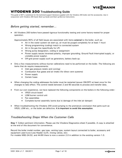
<strong>VITODENS</strong> <strong>200</strong> <strong>Troubleshooting</strong> <strong>Guide</strong><br />
This guide is NOT a substitute for the technical support literature supplied with the Vitodens <strong>200</strong> boiler and the accessories. Use in<br />
conjunction with Vitodens <strong>200</strong> Quick Start-up <strong>Guide</strong> and Start-up/Service Instructions.<br />
<strong>Before</strong> <strong>getting</strong> started, remember…<br />
• All Vitodens <strong>200</strong> boilers have passed rigorous functionality testing and come factory-tested for proper<br />
operation.<br />
Approximately 85% of all field issues are associated with items external to the boiler, such as:<br />
• Air in the water system (at start-up, air must be purged completely for at least 1 hour)<br />
• Wrong programming (coding) match to connected system<br />
• Air in the gas line (specifically for LP)<br />
• Wrong pump designation, coding or assignment<br />
• Power supply issues (reversed polarity, improper grounding, Ground Fault Interrupted supply, or<br />
unstable power supply).<br />
• Off-grid power supply such as generators, battery back-up.<br />
• Only a few measurements without burner calibrations need to be performed on the boiler. The following are<br />
items that do require measurements:<br />
• Inlet gas pressure (static and running)<br />
• Combustion flue gases and air intake (for direct vent systems)<br />
• Power supply<br />
• Certain fuses<br />
• When changing the coding addresses the boiler must be restarted (power ON/OFF) at least once for the<br />
changes to take effect. The control needs between 2 and 60 seconds to process and transfer data.<br />
• From our own experience, we have replaced the following components on the boilers in the following order:<br />
• VR20 circuit board<br />
• LGM burner control unit<br />
• Fan assemblies<br />
• Complete burner assembly (some due to damage of the inlet air damper)<br />
• When troubleshooting the Vitodens <strong>200</strong> avoid jumping to the premature conclusion that parts such as<br />
VR20, LGM etc., or the boiler are defective. It is important to avoid this assumption.<br />
<strong>Troubleshooting</strong> Steps When the Customer Calls<br />
Step 1 Collect pertinent information. Please use the Vitodens Diagnostics sheet if possible. A copy is attached<br />
at the end of this document for convenience.<br />
Record the boiler model number, gas type, venting type, system layout connected to boiler, accessory and<br />
equipment used (Low-Loss Header (LLH), mixing valves, etc).<br />
For models WB2-24/32, and 44/60 there is now a version 2.0 in addition to the existing version 1.0.<br />
5351 934 v1.7 09/2011 Page 1 of 16
Step 2 Follow start-up procedures<br />
For new installations, the first tool is always the Quick Start-up <strong>Guide</strong>. There are Quick Start-up <strong>Guide</strong>s for<br />
each respective boiler size and version. Following all steps in the Quick Start-up <strong>Guide</strong> would resolve up to<br />
90% of the issues. Copies of all Quick Start-up <strong>Guide</strong>s must be kept in the Vitodens <strong>200</strong> Service Binder.<br />
For boilers that have already been in service for some time, see the following steps.<br />
Step 3 Check the programming<br />
Using the information collected in Step 1, go over the programming of the control unit using the updated<br />
product manual. Pay special attention to the coding address “000:___”, “OB8:___”, “045:___”. Most problems<br />
can be solved using the Installation, Start-up/Service and respective accessory manuals that are supplied with<br />
the boiler.<br />
Step 4 Refer to the service guide supplement<br />
Use this <strong>Troubleshooting</strong> <strong>Guide</strong> to solve problems that could not be solved using the Quick Start-up <strong>Guide</strong> and<br />
product service manuals. This <strong>Troubleshooting</strong> <strong>Guide</strong> contains the knowledge and experience of our Service<br />
and Engineering Departments relating to unique and difficult-to-diagnose problems. This guide should help solve<br />
95% of the remaining problems that cannot be solved with steps 1 – 3.<br />
Step 5 Replace components<br />
Once steps 1 – 4 are completed, it may still be necessary to replace a part (e.g. VR20 circuit board, LGM<br />
burner control, etc.). Do not replace any parts prior to completing all previous steps. At this time the<br />
<strong>Viessmann</strong> Service Departments located in Waterloo, Warwick or Langley need to be consulted.<br />
Please avoid calling before having completed the previous steps.<br />
Who to contact…<br />
<strong>Viessmann</strong> Manufacturing<br />
Company Inc.<br />
Waterloo, ON<br />
Tel. (519) 885-6300<br />
Toll-Free (800) 387-7373<br />
<strong>Viessmann</strong> Manufacturing.<br />
Company (U.S.) Inc<br />
Warwick, RI<br />
Tel. (401) 732-0667<br />
Toll-Free (800) 288-0667<br />
<strong>Viessmann</strong> Manufacturing<br />
Company Inc.<br />
Langley, BC<br />
Tel. (604) 533-9445<br />
Toll-Free (877) 853-3288<br />
5351 934 v1.7 Page 2 of 16
5351 934 v1.7<br />
Check pressure transducer. Unplug harness from transducer, then<br />
plug it back in. If the boiler starts, replace the transducer.<br />
Check pressure transducer. Unplug harness from transducer, then<br />
plug it back in. If the boiler starts, replace the transducer.
Field Service Calls Suggested Solution<br />
5 Boiler short cycling on a<br />
short heating circuit<br />
(ie: connected directly<br />
to one mixing valve<br />
heating circuit only “B”)<br />
All model sizes<br />
6 Noise from boiler built-in<br />
bypass valve<br />
Model 6-24/8-32<br />
7 Fuse or circuit breaker<br />
tripping<br />
8 Accessories (HK1,<br />
…etc). BUS<br />
Communication<br />
Problems<br />
9 Ice build-up on outside<br />
vent termination<br />
10 Unusual or erratic<br />
operation of pumps, but<br />
relay test shows normal<br />
functioning<br />
5351 934 v1.7 Page 4 of 16<br />
Set heating curves for heating circuit A, in this case the boiler, equal<br />
to B (single circuit with mixing valve). Lower boiler factory default<br />
differential setting from 8°C to 2°C to 3°C/ 4°F to 5°F (differential<br />
temperature between A and B).<br />
Use of Low Loss Header eliminates this problem.<br />
Systems with zone valves, controlled by other means such as room<br />
thermostat, require separate pressure-activated bypass to be<br />
installed.<br />
See item 4.<br />
Check for hot/neutral polarity in the wall outlet.<br />
Check if GFI is installed (see item 40).<br />
For sizes 44/60 if 0.6 Amp fuse in PPM is blown replace with<br />
equivalent 0.8 Amp fuse. (<strong>Viessmann</strong> PN 9066825)<br />
Interference problem: Check proper connections using updated wiring<br />
diagram. Note: Boiler relay test does not work with <strong>Viessmann</strong> 2-wire<br />
BUS connection (additional mixing valves)<br />
Check all proper coding / scan.<br />
Use shielded/stranded wire.<br />
Usually associated with unusual boiler cycling.(see item 3,4)<br />
Check outdoor sensor for proper reading.<br />
Heating circuits A/B set points (see item 8).<br />
Vent pipe slope (should slope back to boiler).<br />
Replace VR20 board.<br />
Verify all proper coding addresses and timer schedules.<br />
Replace VR20 board.<br />
Model 11-44/15-60; Change coding address 013:001 To 013:000;<br />
pump runs during WWSD if left to 001 value<br />
11 Gas odor outside Check inlet gas pressure at highest input. Use relay test #11 or DHW<br />
call for heat to put boiler at highest input and adjust as required.<br />
Check inlet gas valve mesh screen for blockage, such as pipe debris<br />
and flakes. If this happens frequently, contact <strong>Viessmann</strong>.<br />
12 Boiler only operates<br />
when “Party” mode<br />
button is pressed<br />
Model 11-44/15-60<br />
Pressing the “Party” mode button will activate the DHW recirculation<br />
pump (#20 connection pump output). If heating pump #20A is<br />
mistakenly connected into #20 in an installation without LLH, boiler<br />
will fire only on “Party” mode. Note: If LLH is installed, there is no<br />
DHW recirculation operation since pump #20 becomes boiler pump.
Item Field Service Calls Suggested Solution<br />
13 Electrical Breakers<br />
Tripping and GFI's<br />
Tripping<br />
14 Boiler will not fire on<br />
relay test #10 & #11<br />
Model 11-44/15-60<br />
15 Noisy boiler operation /<br />
Coaxial vent damaged in<br />
shipping/transport.<br />
16 Maximum boiler<br />
temperature 75°C/<br />
167°F (does not go up<br />
to 82°C/ 180°F at<br />
design)<br />
17 Erratic operation of<br />
heating and DHW<br />
18 Boiler power switch not<br />
functional<br />
5351 934 v1.7 Page 5 of 16<br />
PPM Vitodens new Transformer Mar. 17/<strong>200</strong>4 SN:<br />
602026407116<strong>200</strong>4<br />
PM Vitodens new Transformer Apr. 16/<strong>200</strong>4 SN:<br />
602027364911<strong>200</strong>4<br />
Power/Pump modules produced before March 17, <strong>200</strong>4 and Power<br />
Modules produced before April 16, <strong>200</strong>4 have an 'autotransformer'<br />
style of transformer. These may cause breakers and/or GFCI's to trip<br />
if the Line/Neutral are reversed.<br />
Power/Pump modules produced after March 17, <strong>200</strong>4 and Power<br />
Modules produced after April 16, <strong>200</strong>4 have isolation transformer.<br />
These do not cause breakers and/or GFCI's to trip with Line/Neutral<br />
reversal.<br />
FYI: How to read serial number: First six numbers are product part<br />
number, last six numbers are week and year code. Digits in the<br />
middle are sequential numbers<br />
This occurs when Vitodens boiler is connected to one single circuit<br />
with mixing valve. To protect the heating circuit during all relay tests,<br />
mixing valve closes completely. As a result there will be no flow<br />
through the boiler. In this case, another way should be determined to<br />
get flow. Protect any RFH circuit from excessive water temperatures<br />
during relay test.<br />
Improper packaging and handling.<br />
May need packaging reinforcement to protect the vent pipe.<br />
Ensure that coaxial vent pipe adaptor is not deformed. This may<br />
cause air noise or whistling due to the reduced air gap.<br />
Boiler starts modulating down as boiler temperature approaches<br />
75°C/167°F (modulating boiler). Between 75°C/167F to 82°C/180F<br />
boiler operates (on min. fire) until load is satisfied – shut down at<br />
maximum adjustable setting (82°C/180°F) under coding address 042.<br />
Verify correct time and date settings of programming unit. Incorrectly<br />
programmed time clock or timer schedules can cause erratic boiler<br />
operation.<br />
Verify timer schedules when DHW is produced and DHW recirc pump<br />
operation.<br />
Sun and moon dial determines day- and night-time space heating<br />
room temperatures.<br />
When mounting Programming Assembly onto the boiler ensure the<br />
power switch is properly inserted into the rear opening provided on<br />
base of programming unit. Ensure switch (c/w spring) is moving<br />
freely.
<strong>Troubleshooting</strong> Fault Code 06<br />
5351 934 v1.7 Page 6 of 16
Field Service Calls Suggested Solution<br />
19 Problems with multiple<br />
Vitodens installations<br />
Section 2: Fault codes<br />
20 Fault A1<br />
21 Fault A4 (Also see<br />
Service Instructions)<br />
22 B1 fault code<br />
(leads to no Boiler temp<br />
display/no access to<br />
system menu or installer<br />
set up)<br />
23 Fault F4<br />
Model 6-24/8-32<br />
24 Fault 06<br />
Fault 07<br />
5351 934 v1.7 Page 7 of 16<br />
For custom projects, i.e. boilers with Vitocontrol-C, contact KW<br />
Electronic Service. For problems with Vitocontrol-S, refer to<br />
respective manuals and Quick Start-up <strong>Guide</strong> developed by KWE.<br />
Also refer to the issue of “Vitotalk”, addressing the operation of<br />
Cascade Controls.<br />
Acknowledge fault and reset.<br />
Power boiler on and off, remove VR20 circuit board and reinstall.<br />
Power boiler on and off again.<br />
If fault code A1 reappears, replace LGM.<br />
Verify coding address 0B8:006 and change value accordingly.<br />
Low battery charge or dip switch setting of programming unit (rear)<br />
are not set properly.<br />
Replace batteries or check dip switches and clear fault code.<br />
If fault code reappears, turn boiler off, remove VR20 circuit board,<br />
and power the boiler on.<br />
Reinstall VR20 circuit board ensuring that it makes positive contacts.<br />
If boiler starts (after a few seconds), but no temperature display is<br />
present, replace VR20 board and entire programming unit. Usually<br />
boiler operates in the background without proper communication with<br />
programming unit. For example, DHW production activates on a call<br />
for domestic hot water and boiler starts firing.<br />
Air in the system leads to pump racing. Observe boiler temperature;<br />
high temperature spikes may lead to fault 02 (fixed high limit switch);<br />
Bleed air from both systems (domestic hot water and space heating).<br />
Use yellow cap provided with the DHW solenoid valve. Bleed the<br />
pump itself using the screw pump head.<br />
Disconnect pump communication plug #145 and change coding<br />
address 013:001 to 013:000.<br />
If boiler is connected to OFF-grid power supply, contact <strong>Viessmann</strong>.<br />
Air supply to boiler is insufficient.<br />
Check for ice blockage on vent termination.<br />
Check maximum flue pipe length.<br />
Severe local wind conditions.<br />
Check location of side wall terminal (see compliance to all<br />
requirements stated in venting manual).<br />
Defective or blown fuse on orange electronic fan control box (for<br />
44/60 only). Replace entire box.<br />
Defective pressure transducer.
Item Field Service Calls Suggested Solution<br />
25 Fault 14 Gas line needs to be purged extensively on new propane installations<br />
or when boiler was not in operation for extended period of time.<br />
Verify gas regulator and working inlet gas pressure (not static<br />
pressure).<br />
Check ionization current. Check for gaps.<br />
Input voltage to ionization rod must be approx. 160 to 170 VAC (to<br />
ground). If it is not, check polarity (L, N, G) of the power supply.<br />
Check resistance of gas valve coils with power off.<br />
Terminals 1,2→~ 51.7Ω<br />
Terminals 1,3→~ 51.7Ω<br />
Terminals 2,3→~103.5Ω<br />
Check orifice size.<br />
Check spark and ignition transformer.<br />
See also item #11.<br />
26 Fault 14<br />
With two boilers<br />
installed, sometimes<br />
only one goes into lockout<br />
27 Outdoor Temperature<br />
Sensor Fault<br />
Section 3: Unusual screen displays<br />
28 “EXT. program 2,”<br />
appears on screen<br />
29 “Boiler enabling”<br />
appears on the display<br />
30 Boiler temperature<br />
display unit displays<br />
only in °C<br />
5351 934 v1.7 Page 8 of 16<br />
Verify gas pressure inlet with both boilers running high. Run relay test<br />
#11, if needed to simulate, or run DHW for high fire.<br />
If resistance is within limits, wiring is correct and sensor is not<br />
defective, replace VR20 circuit board.<br />
Usually appears at start-up.<br />
Verify all coding addresses.<br />
If problem persists, replace VR20 circuit board.<br />
If problem persists, replace LGM.<br />
If problem persists, replace programming unit control console.<br />
Verify all coding addresses, especially those designated for “Do not<br />
change”). These must stay in their factory default settings.<br />
Cannot be changed to °F when remotely mounting programming unit.
Item Field Service Calls Suggested Solution<br />
31 Dashes displayed<br />
instead of coding<br />
values, e.g. 000- - -.<br />
System address 000:<br />
and OB8: not displayed<br />
when in coding 2.<br />
32 Extreme low<br />
temperature conditions<br />
may cause ice buildup<br />
on side wall and vertical<br />
venting termination<br />
Section 4: Coding address modifications<br />
33 Not enough flow<br />
through boiler<br />
Model 11-44/15-60<br />
5351 934 v1.7 Page 9 of 16<br />
Check all external wiring, and that accessories to the boiler, such as<br />
LLH, DHW and outdoor sensor, specifically X6.1/6.2, are installed<br />
and wired properly.<br />
Ensure no room thermostat is connected to X6.1 and X6.2 (common<br />
field mistake).<br />
Turn boiler on/off a few times and ensure VR20 board is properly<br />
installed with good contacts.<br />
Electromagnetic interference problem with programming unit, such as<br />
in industrial installations and gas heating stations, can be solved by<br />
removing the programming unit and using remote wall-mount base<br />
(room dependent operation) wired into X6.1 and X6.2. Also, install<br />
temperature display unit on boiler (for boiler code requirements).<br />
Ensure that S1 DIP switch at rear temperature display is set to OFF.<br />
Verify proper installation of programming unit console onto the boiler.<br />
Replace entire programming unit console.<br />
Side wall venting screen can be field modified. Please call for<br />
information (see Who to contact…on page 2).<br />
Vertical venting screen can be field modified. Please call for<br />
information (see Who to contact…on page 2).<br />
Boiler pump is undersized. Use Grundfos pumps specified in the<br />
Technical Data Manual, or their equivalent, e.g. TACO 0011, 0014.<br />
34 Coding address 015 “Do not change” 015:000 for 6-24C/6-24/8-32.<br />
“Do not change” 015:001 for 11-44/15-60.<br />
Changing this address from 015:000 to 015:001 on models 6-24C,<br />
6-24, 8-32 will result in boiler firing without circulation pump and<br />
solenoid valve energized on a DHW call for heat. For models 11-44<br />
to15-60 changing the address from 015:001 to 015:000 will result in<br />
DHW pump not energized.<br />
May lead to fault 02.<br />
35 Coding address 017<br />
Model 6-24/8-32<br />
36 OD6 coding (°C to °F) °C for addresses.<br />
°F for display only.<br />
37 Not able to change the<br />
date<br />
“Do not change” 017:001.<br />
Changing this address from factory default setting will result in burner<br />
firing without circulation pump operating. May lead to fault 02. Has<br />
no effect on models WB2-44/60<br />
See coding OC7.
Item Field Service Calls Suggested Solution<br />
38 Snow melt and pool<br />
heating<br />
Section 5: Frequently asked questions<br />
39 Do I need a drain fitting<br />
for the venting system?<br />
40 Can I use stainless steel<br />
Flex pipe to vent?<br />
41 Gap seems too large<br />
around single wall vent<br />
pipe adaptor<br />
42 How do OB8 coding and<br />
anti-legionnaire function<br />
operate?<br />
5351 934 v1.7 Page 10 of 16<br />
Requires installation of a secondary heat exchanger, (Glycol 50%,<br />
max.)<br />
Do not use Vitodens in open loop pool heating system.<br />
You do not need a drain fitting and you do not need a different rain<br />
cap. Boiler will be able to handle the condensation in the vent.<br />
The Vitodens cannot be vented with a flex pipe, even though flex<br />
pipe is made of a UL listed AL-29-4C corrosion resistant material.<br />
These liners are only approved for category I appliances (for lining a<br />
masonry chimney). They are not approved for category IV boilers like<br />
the Vitodens. If you find a flex liner in the North American market<br />
that is approved for category IV, please send us the information to<br />
review.<br />
Use a high-temperature silicon compound to fill in the gap.<br />
The OB8:001 means DHW (without anti-legionnaire function);<br />
The OB8:002 means DHW (with anti-legionnaire function);<br />
Once the DHW sensor is plugged in, address 000:… and OB8 must<br />
be verified and set manually, if required.<br />
anti-legionnaire function:<br />
If there is no call for DHW in a period of 24 hours, the anti-legionnaire<br />
function is initiated by the control and heats up the tank to 140° F /<br />
60° C for a period of 10 minutes. This 10-minute period must lie<br />
outside the programmed DHW switching times for the anti-legionnaire<br />
function so that the control can sense it. See also coding address<br />
OA7 for factory default setting (OA7:060) and possible changes<br />
(OA7:061 to 070). We prefer to leave it at Factory Default setting,<br />
due to the maximum boiler limitations (172.4 °F/78 °C) for DHW. If<br />
coding address OA7 is set to 070, the boiler may need more time to<br />
reach this temperature and therefore might not respond quickly to a<br />
call for heat and be blocked in DHW (especially models WB2-24C,<br />
-24, -32). Do not set DHW temperature controller higher than 140 °F<br />
/ 60 °C. This is applicable to all Vitodens boilers.
Item Field Service Calls Suggested Solution<br />
43 Replacement parts Complete burner assembly comes with NG orifice installed in the gas<br />
valve. Each burner assembly is shipped with LP conversion kit and<br />
comes with Service Instructions and Warning Labels.<br />
Gas valves are shipped with warning labels and instructions, but<br />
without orifice installed. Use the orifice from the existing gas valve.<br />
44 Fault A3 Bus communication problem with Cascade Control.<br />
Check wire to X5 plug for proper connection.<br />
Boiler control or Cascade Control is defective.<br />
45 Replacement ionization<br />
electrodes are not the<br />
same size and shape<br />
Model 11-44/15-60<br />
5351 934 v1.7 Page 11 of 16<br />
There are three different designs of electrodes. All are compatible.<br />
46 Fault F3 Check connections/wiring to low-loss header sensor of Cascade<br />
Control<br />
Check accessories, e.g. outdoor temp. sensor, low-loss header sensor<br />
of Cascade control<br />
Check Cascade Control. Replace if necessary.<br />
47 Fault CC Reset boiler. If red light reappears and boiler goes into lockout mode,<br />
replace LGM 29.XX.<br />
48 Boiler does not ramp up<br />
to high fire (specially in<br />
multiple boiler systems<br />
with cascade control).<br />
Check inlet gas valve mesh screen for blockage. Clean it. If the issue<br />
reports more than 2 times a year contact <strong>Viessmann</strong>.
<strong>VITODENS</strong> <strong>200</strong><br />
Diagnostic Sheets<br />
CAUTION<br />
The installation, adjustment, service,<br />
and maintenance of this product must<br />
be done by a licensed professional<br />
heating contractor who is qualified<br />
and experienced in the installation,<br />
service and maintenance of hot water<br />
boilers. There are no user serviceable<br />
parts on the boiler, burner, or control.<br />
WARNING<br />
Ensure main power supply to<br />
equipment, the heating system, and<br />
all external controls have been<br />
deactivated. Close main gas supply<br />
valve. Take precautions in all<br />
instances to avoid accidental<br />
activation of power during service<br />
work.<br />
Please include all of the information requested to facilitate the diagnosis and fax it back to<br />
_______________________________________________ at _______________________________<br />
Mechanical Contractor: _____________________________________________________________________________________________<br />
Address: _____________________________________________________________________________________________<br />
_____________________________________________________________________________________________<br />
Tel: _____________________________________________________________________________________________<br />
Contact Person: _____________________________________________________________________________________________<br />
Date Installed: _____________________________________________________________________________________________<br />
Project Name: _____________________________________________________________________________________________<br />
Project Address: _____________________________________________________________________________________________<br />
_____________________________________________________________________________________________<br />
Tel: _____________________________________________________________________________________________<br />
Contact Person: _____________________________________________________________________________________________<br />
Altitude of Installation: ________________________________________ feet<br />
Installation in: Residence / Home Commercial / Industrial<br />
Heating Boiler<br />
Model: WB2- 6-24C 6-24 8-32 11-44 15-60<br />
ASME Serial No.: _____________________________________________________________________________________________<br />
Fuel Supply: NG LP<br />
DHW Model (if applicable): Brand: ________________________________ Size: ___________________________________
Boiler Installation Checklist<br />
The following information must be made available to us to assist in the diagnosis.<br />
System Layout<br />
Using the booklets supplied with the boiler provide the following information:<br />
1. Date on cover of Installation Instructions: month ____________ year ____________<br />
2. The page number of the Installation Instructions for the system type: Page No. ____________<br />
Installation and Activation Requirements. Please Provide:<br />
Heat loss calculations<br />
Flow calculations (GPM at ft head for each pump in system)<br />
DHW Tank coil flow rate and head ____________ ____________<br />
Venting material: ______________________________________________ (include sketch)<br />
Gas pressure measured at full fire _____________________<br />
Gas valve screws x, y readjusted? Yes No<br />
Boiler water pressure ____________ temperature ____________<br />
Electrical polarity and grounding at #40 plug confirmed. L & N terminal ____________<br />
Power source: grid generator inverter<br />
External gas filter installed Yes No<br />
If LLH installed, is <strong>Viessmann</strong> #5 sensor connected to boiler? Yes No No LLH<br />
Single boiler installation with Cascade control without Cascade control<br />
Boiler / System Parameters Checklist. Please ensure that you have reviewed the items below:<br />
Wiring in Power Pump Module correct (quick set-up) Max temperature set A / B<br />
Wiring in Vitodens correct (schematic)<br />
Differential set-point<br />
Coding addresses match system<br />
DHW set-point / optimum switch position<br />
Relay test as per manual<br />
Burner micro-amp signal measured<br />
Sensor test as per manual<br />
Saved fault code retrieval<br />
Operating status information O.K.<br />
Vitodens control batteries, remote mount<br />
Mixing valve direction, dip switches<br />
Remote enable / disable function<br />
Time and date set correctly<br />
LLH sensor actual temperature reading<br />
All timer schedules<br />
Btu/h matches load<br />
Heating curves A / B<br />
Integration with other heat sources<br />
Shift A / B<br />
Vitodens control DIP switch (S1 & S2) at the back
System Sketch<br />
If the diagram as provided in the Installation Instructions was not followed, the following information is required. Include<br />
this information on the separate sheet attached. If floor heat design software can assist in answering the following<br />
questions, please include it in your response.<br />
Piping schematic including boiler feed<br />
Piping diameters and lengths<br />
Individual circuit flow, GPM required<br />
Foot of head for each circuit<br />
Calculated Delta T for each circuit<br />
Address Recorded Value<br />
000<br />
003<br />
005<br />
007<br />
008<br />
010<br />
011<br />
013<br />
Address Recorded Value<br />
042<br />
044<br />
045<br />
046<br />
099<br />
0A0<br />
0A2<br />
0A7<br />
0A9<br />
Circuit water temperature requirements<br />
Circuit Btu requirements<br />
Total Btu load<br />
Circulator sizes (model numbers)<br />
Address Recorded Value<br />
015<br />
017<br />
108<br />
019<br />
020<br />
027<br />
028<br />
038<br />
Address Recorded Value<br />
0B2<br />
0B3<br />
0B8<br />
0C1<br />
0C5<br />
0D7<br />
Scan 1<br />
Scan 2
System Sketch
<strong>Viessmann</strong> Manufacturing<br />
Company Inc.<br />
Waterloo, ON Canada<br />
Tel. (519) 885-6300<br />
Fax (519) 885-0887<br />
<strong>Viessmann</strong> Manufacturing<br />
Company (U.S.) Inc.<br />
Warwick, RI USA<br />
Tel. (401) 732-0667<br />
Fax (401) 732-0590<br />
<strong>Viessmann</strong> Sales Center<br />
Langley, BC Canada<br />
Tel. (604) 533-9445<br />
Fax. (604) 533-9439<br />
Printed on environmentally friendly<br />
(recycled and recyclable) paper.<br />
5351 934 v1.7 Technical information subject to change without notice