Installation Instructions VITOCELL r 100-V - Viessmann
Installation Instructions VITOCELL r 100-V - Viessmann
Installation Instructions VITOCELL r 100-V - Viessmann

Create successful ePaper yourself
Turn your PDF publications into a flip-book with our unique Google optimized e-Paper software.
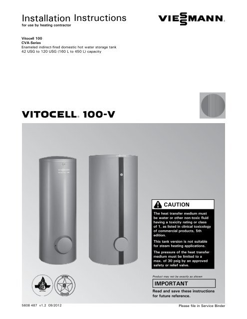
<strong>Installation</strong> <strong>Instructions</strong><br />
for use by heating contractor<br />
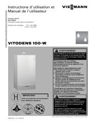
Vitocell <strong>100</strong><br />
CVA-Series<br />
Enameled indirect-fired domestic hot water storage tank<br />
42 USG to 120 USG (160 L to 450 L) capacity<br />
<strong>VITOCELL</strong> r <strong>100</strong>-V<br />
5608 487 v1.2 09/2012<br />
CAUTION<br />
The heat transfer medium must<br />
be water or other non-toxic fluid<br />
having a toxicity rating or class<br />
of 1, as listed in clinical toxicology<br />
of commercial products, 5th<br />
edition.<br />
This tank version is not suitable<br />
for steam heating applications.<br />
The pressure of the heat transfer<br />
medium must be limited to a<br />
max. of 30 psig by an approved<br />
safety or relief valve.<br />
Product may not be exactly as shown<br />
IMPORTANT<br />
Read and save these instructions<br />
for future reference.<br />
Please file in Service Binder
2<br />
Introduction<br />
Safety, <strong>Installation</strong> and Warranty Requirements<br />
Vitocell <strong>100</strong>-V <strong>Installation</strong> <strong>Instructions</strong><br />
Please ensure that these instructions are read and understood before commencing installation. Failure to comply with<br />
the instructions listed below and details printed in this manual can cause product/property damage, severe personal<br />
injury, and/or loss of life. Ensure all requirements below are understood and fulfilled (including detailed information<br />
found in manual subsections).<br />
g Licensed professional heating contractor<br />
The installation, adjustment, service and maintenance<br />
of this equipment must be performed by a licensed<br />
professional heating contractor.<br />
�Please see section entitled<br />
“Important Regulatory and <strong>Installation</strong><br />
Requirements”.<br />
g Product documentation<br />
Read all applicable documentation before commencing<br />
installation. Store documentation near product in a<br />
readily accessible location for reference in the future<br />
by service personnel.<br />
�For a listing of applicable literature,<br />
please see section entitled “Important<br />
Regulatory and <strong>Installation</strong> Requirements”.<br />
g Advice to owner<br />
Once the installation work is complete, the heating<br />
contractor must familiarize the system operator/<br />
ultimate owner with all equipment, as well as safety<br />
precautions/requirements, shutdown procedure, and<br />
the need for professional service annually before the<br />
heating season begins.<br />
g Warranty<br />
Information contained in this and<br />
related product documentation must<br />
be read and followed. Failure to do<br />
so renders the warranty null and void.<br />
In solar applications:<br />
CAUTION<br />
The heat transfer medium must be either potable water<br />
or contain only substances which are recognized as safe<br />
by the U.S. Food and Drug Administration.<br />
The Pressure of the heat transfer medium must be<br />
maintained less than the normal minimum operating<br />
pressure of the potable water system<br />
5608 487 v1.2
Introduction<br />
Safety<br />
General Information<br />
Set-up and Connections<br />
Additional Information<br />
Safety, <strong>Installation</strong> and Warranty Requirements..............2<br />
Licensed professional heating contractor.....................2<br />
Product documentation.............................................2<br />
Advice to owner......................................................2<br />
Warranty................................................................2<br />
Important Regulatory and <strong>Installation</strong> Requirements........4<br />
Codes.....................................................................4<br />
Mechanical room.....................................................4<br />
Working on the equipment........................................4<br />
Technical literature..................................................4<br />
About These <strong>Instructions</strong>.............................................5<br />
Product Information.....................................................5<br />
42 USG to 79 USG (160 L to 300 L) capacity............5<br />
Tank Connections.......................................................6<br />
Tank Set-up...............................................................7<br />
42 to 79 USG (160 to 300 Liter) Tank <strong>Installation</strong>........8<br />
Thermal insulation and thermometer installation..........8<br />
Temperature sensor installation for solar operation<br />
using 42 to 79 USG (160 to 300 L) tanks..................9<br />
Checking anode connections.....................................9<br />
120 USG (450 Liter) Tank <strong>Installation</strong>........................10<br />
Temperature sensor installation (when using<br />
a Vitotronic 200 / 300 or Vitodens 200)...................10<br />
Temperature sensor installation for solar operation<br />
using 120 USG (450 L) tank...................................10<br />
Levelling and bottom thermal insulation....................11<br />
Fitting the thermal insulating jacket..........................12<br />
Fitting the thermometer and thermometer sensor<br />
(if supplied) and covers...........................................13<br />
Aquastat <strong>Installation</strong> (when using a vitotronic <strong>100</strong>).......14<br />
Boiler Water Connections (heat exchanger connection)...15<br />
Recommended piping for solar application<br />
with an additional tank..........................................15<br />
Domestic Water Connections......................................16<br />
Recirculation Connections..........................................18<br />
Saving Energy........................................................18<br />
Multiple Tank Set-up [only for 79 and 120 USG<br />
(300 and 450 L) capacities].......................................19<br />
Pressure Drop Information..........................................21<br />
Pressure drop on domestic hot water side<br />
(secondary circuit)..................................................21<br />
Pressure drop on heating water side<br />
(primary circuit).....................................................21<br />
Inspection Opening.................................................22<br />
Post <strong>Installation</strong>.......................................................22<br />
Service binder........................................................22<br />
Start-up information...............................................22<br />
5608 487 v1.2 Vitocell <strong>100</strong>-V <strong>Installation</strong> <strong>Instructions</strong> Contents<br />
Page<br />
3
4<br />
Safety<br />
Important Regulatory and <strong>Installation</strong> Requirements<br />
Codes<br />
The installation of indirect-fired hot water storage tanks<br />
in boilers and solar system application might be governed<br />
by individual local rules and regulations for this type of<br />
product, which must be observed. Always use latest<br />
editions of codes.<br />
In the Commonwealth of Massachusetts, all plumbing<br />
work must be done by a licensed plumber or gas-fitter<br />
and for gas installations, all gas piping must be done by a<br />
licensed gas-fitter.<br />
Mechanical room<br />
Ensure the mechanical room complies with the<br />
requirements of the system design guideline and/or<br />
Technical Data Manual (available from your <strong>Viessmann</strong><br />
sales representative).<br />
The tank must be installed in a mechanical room which is<br />
never subject to freezing temperatures.<br />
Ensure water in tank is drained if not in use and danger of<br />
freezing exists in the mechanical room.<br />
WARNING<br />
If the heating system itself is to be filled with Glycol or<br />
any other antifreeze, the system fill must be of non-toxic<br />
or food grade antifreeze. In any circumstance, a non-toxic<br />
fluid must be used. Ensure a copy of the Material Safety<br />
Data Sheet (MSDS) is supplied to the operator/ultimate<br />
owner of the system. The use of <strong>Viessmann</strong> supplied<br />
“Tyfocor-HTL” solar fill is recommended for the solar<br />
heating circuit.<br />
Working on the equipment<br />
The installation, adjustment, service, and maintenance of<br />
this equipment must be done by a licensed professional<br />
heating contractor who is qualified and experienced in<br />
the installation, service, and maintenance of hot water<br />
heating systems. There are no user serviceable parts on<br />
this equipment.<br />
Ensure main power supply to equipment, the heating<br />
system, and all external controls has been deactivated.<br />
Close main oil or gas supply valve. Take precautions to<br />
avoid accidental activation of power during service work.<br />
Technical literature<br />
Literature applicable to all aspects of the Vitocell:<br />
- Technical Data Manual<br />
- <strong>Installation</strong> <strong>Instructions</strong><br />
- Start-up/Service <strong>Instructions</strong><br />
- Operating <strong>Instructions</strong> and User’s Information Manual<br />
Vitocell <strong>100</strong>-V <strong>Installation</strong> <strong>Instructions</strong><br />
�Please carefully read this manual prior to attempting<br />
installation. Any warranty is null and void if these<br />
instructions are not followed.<br />
This product must be installed observing not only the<br />
information and instruction provided in the pertinent<br />
product literature (see list on following page), but also<br />
all local, provincial/state plumbing and building codes,<br />
as they apply to this product and all periphery<br />
equipment.<br />
For information regarding other <strong>Viessmann</strong> System<br />
Technology componentry, please reference<br />
documentation of the respective product (available from<br />
your <strong>Viessmann</strong> sales representative).<br />
We offer frequent installation and service seminars to<br />
familiarize our partners with out products. Please inquire.<br />
�The completeness and functionality of field supplied<br />
electrical controls and components must be verified<br />
by the heating contractor. These include low-water<br />
cut-offs, flow switches (if used), staging controls,<br />
pumps, motorized valves, air vents, thermostats,<br />
temperature controls, etc.<br />
�Leave all literature at the installation site and advise the<br />
system operator/ultimate owner where the literature<br />
can be found. Contact <strong>Viessmann</strong> for additional copies.<br />
5608 487 v1.2
About These <strong>Instructions</strong><br />
Take note of all symbols and notations intended to draw attention to potential hazards or important product information.<br />
These include “WARNING”, “CAUTION”, and “IMPORTANT”. See below.<br />
WARNING<br />
Indicates an imminently hazardous situation which, if<br />
not avoided, could result in substantial product/property<br />
damage, serious injury or loss of life.<br />
CAUTION<br />
Indicates an imminently hazardous situation which, if not<br />
avoided, may result in minor injury or product/property<br />
damage.<br />
�<br />
IMPORTANT<br />
Product Information<br />
42 USG to 120 USG (160 L to 450 L) capacity<br />
Enameled indirect-fired domestic hot water storage tank<br />
with one heat exchanger coil for use with hot water heating<br />
boilers, residential/commercial heating plants, and lowtemperature<br />
heating systems.<br />
These tank versions are not suitable for steam heating<br />
applications.<br />
5608 487 v1.2 Vitocell <strong>100</strong>-V <strong>Installation</strong> <strong>Instructions</strong><br />
General Information<br />
�Warnings draw your attention to the presence of<br />
potential hazards or important product information.<br />
�Cautions draw your attention to the presence of<br />
potential hazards or important product information.<br />
�Helpful hints for installation, operation or maintenance<br />
which pertain to the product.<br />
�This symbol indicates that additional, pertinent<br />
information is to be found.<br />
�This symbol indicates that other instructions must be<br />
referenced.<br />
5
6<br />
Set-up and Connections<br />
Tank Connections<br />
DHW tank connections 42 to 79 USG (160 to 300 L)<br />
DHW tank connections 120 USG (450 L)<br />
Vitocell <strong>100</strong>-V <strong>Installation</strong> <strong>Instructions</strong><br />
Supplied adaptor sizes Vitocell <strong>100</strong>-V<br />
Part Size 42/53 USG<br />
(160/200 L)<br />
Legend<br />
DHW Domestic hot water supply<br />
RT Recirculation tapping<br />
TS/AQ DHW temperature sensor or aquastat of boiler<br />
control (upper indirect coil)<br />
BWS Boiler water supply * 1<br />
BWR Boiler water return * 1<br />
DCW Domestic cold water supply<br />
GND Grounding connection (casing) 42 to 79 USG<br />
(160 to 300 L) only<br />
*1 The upper indirect coil is provided for connection<br />
to a boiler or a heat pump.<br />
79 USG<br />
(300 L)<br />
B Brass cap c in. 1 --<br />
A Brass adaptor c in. 2 --<br />
C Brass tee c in. 1 --<br />
F Brass adaptor 1 in. + gasket 2 2<br />
B Brass cap 1 in. -- 1<br />
A Brass adaptor 1 in. -- 2<br />
C Brass tee 1 in. -- 1<br />
E Temperature and<br />
pressure relief valve<br />
c in. 1 1<br />
Supplied adaptor sizes Vitocell <strong>100</strong>-V<br />
Part Size 120 USG (450 L)<br />
B Brass cap 1 in. 1<br />
A Brass adaptor 1 in. 1<br />
A Brass adaptor 1a in. 2<br />
C Brass tee 1a in. 1<br />
D Reducer hex bushing 1a in. x c in. 1<br />
E Temperature and<br />
pressure relief valve<br />
c in. 1<br />
F Brass adaptor 1 in. + gasket 2<br />
5608 487 v1.2
Tank Set-up<br />
- For narrow passageways, remove upper and lower<br />
portion of crating and carry DHW tank to its installation<br />
location by means of crating boards mounted on the tank.<br />
- Position tank carefully and remove wood crating.<br />
- Locate tank(s) on flooring or foundation capable of<br />
supporting the weight of the tank(s) filled with water.<br />
- The tank does not require a special foundation and<br />
can be placed directly on the floor. If, for cleanliness<br />
purposes, the tank is to be kept off the floor, a<br />
foundation for each tank or tanks can be used.<br />
Recommended installation clearances for service access<br />
Rear in. (mm) 18 (460)<br />
Sides May be reduced if rear pipe connections<br />
can be reached with less clearance<br />
5608 487 v1.2 Vitocell <strong>100</strong>-V <strong>Installation</strong> <strong>Instructions</strong><br />
in. (mm) 12 (300)<br />
Top in. (mm) 36 (900)<br />
Front in. (mm) 24 (600)<br />
Minimum clearances to combustibles<br />
CAUTION<br />
All sides in. (mm) 0 (0)<br />
Floor combustible<br />
1. Apply Loctite 55 as per supplied instructions to each<br />
tank nipple. Use Loctite 55 provided in the installation<br />
fittings package.<br />
2. Connect female ends of brass adaptors to the tank<br />
nipples.<br />
CAUTION<br />
Do not overtighten the adaptors as this may damage<br />
the Ceraprotect emamel of the tank.<br />
Install the DHW tank in a frost-protected and draft-free<br />
room. Otherwise it must be drained when not in use, in<br />
order to reduce the risk of damages caused by freezing.<br />
IMPORTANT<br />
Set-up and Connections<br />
Provide sufficient clearances towards the wall to allow<br />
the aquastat to be operated (if installed).<br />
7
Set-up and Connections<br />
42 to 79 USG (160 to 300 Liter) Tank <strong>Installation</strong><br />
8<br />
Thermal insulation and thermometer installation<br />
All required components are included in the insulation<br />
jacket carton.<br />
Note: the 42 to 79 USG (160 and 300 L) tank comes<br />
with the insulation jacket installed.<br />
1. Position and level the DHW tank with its leveling bolts.<br />
IMPORTANT<br />
Do not extend the leveling bolts beyond an overall<br />
length of 1½ in. (35 mm).<br />
2. Mount sensor on the outside of the sensor spring-clip<br />
(not in the center groove) so that it is flush with the<br />
front of the sensor spring-clip.<br />
3. Snap sensor cabling into plastic clip of sensor<br />
mounting equipment.<br />
IMPORTANT<br />
Never wrap insulating tape around the sensor.<br />
4. Completely insert sensor mounting hardware along<br />
with sensor into sensor well.<br />
Vitocell <strong>100</strong>-V <strong>Installation</strong> <strong>Instructions</strong><br />
5. Remove top cover and insulation blanket.<br />
6. Remove cap from thermometer opening.<br />
7. Slide thermometer sensor cable through thermometer<br />
opening in the panel and insert thermometer.<br />
8. Completely insert sensor into metal clip on flange<br />
(check anode connection on page 8). Install the<br />
insulation blanket and top cover.<br />
Note: For applications with Vitotronic <strong>100</strong> control,<br />
use supplied plastic clip and two screws to<br />
secure Honeywell bulb capillary. For applications<br />
with the Vitotronic 200 or 300 control option,<br />
use supplied plastic clip and two screws to<br />
secure sensor cable to the tank sheet metal.<br />
Note: For Solar Domestic Hot Water with Vitosolic 200,<br />
SCU 124 or SCU 224, use supplied plastic clip<br />
and two screws to secure sensor cable to the<br />
tank sheet metal.<br />
5608 487 v1.2
42 to 79 USG (160 to 300 Liter) Tank <strong>Installation</strong> (continued)<br />
Temperature sensor installation for solar operation using<br />
42 to 79 USG (160 to 300 L) tanks<br />
The temperature sensor for solar operation is included in<br />
the solar control unit package.<br />
The brass elbow with sensor well is available as an option<br />
and must be used when solar connection is required.<br />
Checking anode connections<br />
Ensure the grounding wire is properly secured to the<br />
magnesium anode.<br />
Legend<br />
A Magnesium anode<br />
B Grounding wire<br />
1. For solar operation, install the sensor well into the<br />
brass elbow and connect the assembly to the solar<br />
return line.<br />
2. Insert the temperature sensor until it bottoms out<br />
inside the sensor well.<br />
IMPORTANT<br />
Never wrap insulating tape around the sensor. Do not<br />
install solar tank sensor anywhere other than the brass<br />
elbow with sensor well.<br />
IMPORTANT<br />
When connecting an externally powered anode to the top<br />
flange lid, separate the magnesium anode in the bottom<br />
flange lid from the grounding cable. The magnesium anode<br />
may remain installed.<br />
5608 487 v1.2 Vitocell <strong>100</strong>-V <strong>Installation</strong> <strong>Instructions</strong> Set-up and Connections<br />
9
10<br />
Set-up and Connections<br />
120 USG (450 Liter) Tank <strong>Installation</strong><br />
Temperature sensor installation (when using a Vitotronic<br />
200 / 300 or Vitodens 200)<br />
Temperature sensor installation for solar operation using<br />
120 USG (450 L) tank<br />
The temperature sensor for solar operation is included in<br />
the solar control unit package.<br />
The brass elbow with sensor well is available as an option<br />
and must be used when solar connection is required.<br />
Vitocell <strong>100</strong>-V <strong>Installation</strong> <strong>Instructions</strong><br />
1. Mount sensor on the outside of the sensor spring-clip<br />
(not in the center groove) so that it is flush with the<br />
front of the sensor spring-clip.<br />
2. Snap sensor cabling into plastic clip of sensor mounting<br />
equipment.<br />
CAUTION<br />
Never wrap sensor with any type of tape or insulation.<br />
3. Completely insert sensor mounting equipment along<br />
with sensor into sensor well.<br />
4. For applications with Vitotronic <strong>100</strong> control, use<br />
supplied plastic clip and two screws to secure<br />
Honeywell bulb capillary. For applications with the<br />
Vitotronic 200 or 300 control option, use supplied<br />
plastic clip and two screws to secure sensor cable<br />
5 to the tank sheet metal.<br />
Note: When using a Vitotronic <strong>100</strong> boiler control, refer<br />
to page 14 for aquastat installation.<br />
1. For solar operation, install the sensor well/brass elbow<br />
and connect the assembly to the solar return line.<br />
2. Insert the temperature sensor until it bottoms out<br />
inside the sensor well.<br />
IMPORTANT<br />
Never wrap insulating tape around the sensor. Do not<br />
install solar tank sensor anywhere other than the brass<br />
elbow with sensor well.<br />
3. Tighten screws to secure sensor (do not over tighten).<br />
5608 487 v1.2
120 USG (450 Liter) Tank <strong>Installation</strong> (continued)<br />
Levelling and bottom thermal insulation<br />
All necessary parts for enclosure assembly are packaged<br />
in a separate carton.<br />
CAUTION<br />
The thermal insulation must not come in contact with<br />
open flames. Exercise extreme caution when welding<br />
and soldering.<br />
1. Fit the thermal insulation blanket below the tank prior<br />
to the installation of the tank itself.<br />
2. Position and level the DHW tank with its leveling bolts.<br />
IMPORTANT<br />
Do not extend the leveling bolts beyond an overall<br />
length of 1½ in. (35 mm).<br />
5608 487 v1.2 Vitocell <strong>100</strong>-V <strong>Installation</strong> <strong>Instructions</strong> Set-up and Connections<br />
11
12<br />
Set-up and Connections<br />
120 USG (450 Liter) Tank <strong>Installation</strong> (continued)<br />
Fitting the thermal insulation jacket<br />
Note: - insulation remnants must not enter the tank<br />
through the tank connections.<br />
- 2 people are recommended to complete this work.<br />
Vitocell <strong>100</strong>-V <strong>Installation</strong> <strong>Instructions</strong><br />
1. Fit both halves of the insulation jacket close to the tank.<br />
Orient the jacket so the profile cutouts match the tank<br />
fittings.<br />
2. At the rear of the tank, install all 6 clip closures evenly<br />
to both halves of the insulation jacket.<br />
3. At the front of the tank, install all 6 clip closures evenly<br />
to both halves of the insulation jacket.<br />
4. At the rear of the tank, tighten all 6 clip closures until<br />
both halves of the insulation jacket meet.<br />
5. At the front of the tank, tighten all 6 clip closures<br />
until both halves of the insulation jacket meet.<br />
5608 487 v1.2
120 USG (450 Liter) Tank <strong>Installation</strong> (continued)<br />
Fitting the thermometer and thermometer sensor<br />
(if supplied) and covers<br />
1. Smooth out the insulation jacket by tapping the jacket<br />
evenly against the tank.<br />
2. Route thermometer capillary tube through the<br />
front cover hole and insulation jacket, then snap the<br />
thermometer in place.<br />
3. Insert the thermometer probe under the clip.<br />
4. Install the front cleanout cover and the front lower<br />
seam cover.<br />
5. Install the upper front seam cover.<br />
6. Install the back seam cover.<br />
7. Install the top insulation and press down the edges<br />
as shown.<br />
8. Install the top lid and press the logo A into the lid.<br />
Note: Seal the hole in the seam cover below the<br />
thermometer with a cover.<br />
5608 487 v1.2 Vitocell <strong>100</strong>-V <strong>Installation</strong> <strong>Instructions</strong> Set-up and Connections<br />
13
14<br />
Set-up and Connections<br />
Aquastat <strong>Installation</strong> (when using a Vitotronic <strong>100</strong>)<br />
IMPORTANT<br />
Probe style aquastat<br />
Use a Loctite 55 string and pipe dope on all threaded<br />
nipples on tank.<br />
Vitocell <strong>100</strong>-V <strong>Installation</strong> <strong>Instructions</strong><br />
Where a Vitotronic <strong>100</strong> and a <strong>Viessmann</strong> Power/Pump<br />
Control Module (accessory) are utilized to control DHW<br />
production, follow these aquastat mounting instructions:<br />
1. Insert the extended capillary of the aquastat (supplied<br />
with <strong>Viessmann</strong> Power/Pump Control Module, not<br />
illustrated) fully and completely into sensor well. Mount<br />
aquastat inconspicuously on tank paneling.<br />
Follow instructions below with regard to sensor and<br />
spring clip installation.<br />
... if aquastat is to be mounted remote from the tank well,<br />
2. Align sensor bulb with spring clip.<br />
3. Slide assembly into well.<br />
4. The retention spring clip must press the bulb properly<br />
to ensure surface contact with the well.<br />
... if aquastat is to be mounted directly on the tank well,<br />
5. Mount aquastat with holding clip supplied directly onto<br />
well. Bend capillary tube into groove opening to allow<br />
for mounting of aquastat.<br />
WARNING<br />
To ensure optimum, safe operation, the supplied<br />
stainless steel well must be installed. The well diameter<br />
is large enough to accommodate a wide variety of<br />
sensing bulbs.<br />
Always use spring clip to ensure proper contact of<br />
capillary bulb against the stainless steel well for proper<br />
sensing/heat transfer!<br />
Grounding connection<br />
Connect the grounding in accordance with the requirements<br />
stipulated by your local electricity supply company and<br />
current local regulations.<br />
WARNING<br />
The operating aquastat and any secondary high limit<br />
aquastat of the tank must be set such that the DHW<br />
temperature inside the tank never exceeds 203° F (95° C).<br />
WARNING<br />
Domestic hot water temperatures over 125° F (52° C)<br />
can cause severe burns instantly or death from scalds.<br />
Children, disabled and elderly are at highest risk of<br />
being scalded.<br />
Feel water before bathing or showering.<br />
Temperature limiting valves are available and must<br />
be used where domestic hot water storage tank<br />
temperatures exceed 140° F (60° C).<br />
5608 487 v1.2
Boiler Water Connections (heat exchanger connection)<br />
Recommended piping for solar application with an additional tank<br />
Legend<br />
A Solar collector<br />
B High limit safety cut-out<br />
C Filling valve<br />
D Solar-Divicon<br />
E Vitocell <strong>100</strong>-V<br />
F Individual DHW tank heating system<br />
G Anti-scald tempering valve<br />
WARNING<br />
Due to the potentially high DHW temperatures generated<br />
by the solar heating system, the domestic hot water<br />
temperature must be limited to a maximum of 140º F (60º C)<br />
by installing a anti-scald tempering valve. The tempering<br />
valve does not completely eliminate the risk of scalding at<br />
the tap. The installation of a mixing tap is recommended.<br />
IMPORTANT<br />
Use a Loctite 55 string and pipe dope on all threaded<br />
nipples on tank.<br />
1. For boiler water supply temperatures over 203° F (95° C):<br />
Remove plastic supply and return grommets<br />
(grommets are left-threaded).<br />
2. Pipe supply line with an incline and install an air vent<br />
valve at the highest point.<br />
3. For boiler water supply temperatures over 230° F<br />
(110° C):<br />
Install a type-tested high limit safety cut-out, if no other<br />
has previously been installed in this system. For this<br />
purpose, install a dual thermostat (high limit thermostat<br />
and high limit safety cut-out).<br />
4. Close off test nipples which are not used for the<br />
installation of a probe or sensor.<br />
5608 487 v1.2 Vitocell <strong>100</strong>-V <strong>Installation</strong> <strong>Instructions</strong> Set-up and Connections<br />
15
16<br />
Set-up and Connections<br />
Domestic Water Connections<br />
Note: - Connect all pipe work with detachable fittings.<br />
- Seal connections that are not required with red<br />
brass caps.<br />
- Equip the DHW circulation pipe with circulation<br />
pump, check valve and time switch. Gravity<br />
operation is only feasible to a limited degree.<br />
- Always install DHW group of tanks with<br />
connected DHW circulation.<br />
1. Pipe together boiler and tank as illustrated. Connections<br />
must be accessible for service (use factory supplied<br />
adaptors).<br />
2. Insulate domestic hot water supply piping.<br />
IMPORTANT<br />
This is a simplified conceptual drawing only! Piping and<br />
necessary componentry must be field verified. Proper<br />
installation and functionality in the field are the responsibility<br />
of the heating contractor.<br />
Legend<br />
A Spring-loaded flow check valve<br />
B Discharge pipe<br />
IMPORTANT<br />
Vitocell <strong>100</strong>-V <strong>Installation</strong> <strong>Instructions</strong><br />
C Anti-scald tempering valve (field supplied)<br />
SV Shut-off valve<br />
FV Flow check valve<br />
PR Pressure reducing valve<br />
D Drain<br />
DCW Cold water supply lines<br />
PGC Pressure gage connection<br />
E Precharged expansion tank (required where<br />
backflow preventer is installed; check local<br />
plumbing codes and requirements)<br />
BP1 Backflow preventer<br />
BP2 Backflow preventer<br />
T&P Temperature and pressure relief valve<br />
DW Water filter<br />
DHW Domestic hot water supply<br />
RP Recirculation pipe<br />
RPU Recirculation pump<br />
Use a Loctite 55 string and pipe dope on all threaded<br />
nipples on tank.<br />
5608 487 v1.2
Domestic Water Connections (continued)<br />
Always ensure the use of type approved devices.<br />
Safety devices include the following components:<br />
- Isolation valves<br />
- Drain valve<br />
- Pressure reducing valve<br />
where required by local jurisdiction<br />
- Drinking water filter<br />
where required by local jurisdiction<br />
- Backflow preventer<br />
Where backflow preventers are required, a domestic<br />
water expansion tank installation is required in the<br />
cold water inlet piping before the cold water enters<br />
the tank. The backflow device must be installed<br />
according to the manufacturer’s installation<br />
instructions. Observe local codes and regulations.<br />
- Tempering valve<br />
A tempering valve must be field installed where<br />
storage tank (domestic hot water temperature)<br />
exceeds local restricted temperatures or 140° F<br />
(60° C). Check code requirements.<br />
IMPORTANT<br />
In situations where a booster pump is used to maintain<br />
DHW pressure, <strong>Viessmann</strong> strongly recommends the<br />
installation of an oversized large expansion tank to<br />
ensure longer, less frequent pump cycles with less<br />
severe pressure gradients. If possible, use flexible piping<br />
before and after booster pump to isolate system piping<br />
from vibration and shocks.<br />
- Temperature and pressure relief valve<br />
A temperature and pressure relief valve (T&P valve)<br />
is supplied with the tank. The heating contractor must<br />
install the valve on each tank in a method meeting<br />
code requirements.<br />
If local codes require a different relief valve, consult<br />
<strong>Viessmann</strong> Manufacturing for a substitute valve.<br />
The tank is approved for 150 psig. Maximum operating<br />
pressure is 150 psig.<br />
The T&P valve supplied with the tank is tested under<br />
ANSI Z21.22 Code for Relief Valves and Automatic<br />
Gas Shut-off Devices for Hot Water Supply Systems.<br />
Watts Model 40XL-8 150 psig<br />
ASME pressure<br />
steam rating<br />
CSA temperature<br />
steam rating<br />
1438 MBH<br />
205 MBH<br />
Relief temperature 210° F (99° C)<br />
Inlet thread c” male<br />
Outlet thread c” female<br />
The valve supplied with the tank is manufactured by Watts<br />
Industries (Model 40XL-8) set to <strong>100</strong> psig for Canadian<br />
installations and set to 150 psig for US installations<br />
(where applicable). The valve is ASME pressure steam<br />
rated for 998 MBH and CSA temperature steam rated for<br />
200 MBH. It is tested under ANSI Z21.22 code for Relief<br />
Valves and Automatic Gas Shut-off Devices for Hot Water<br />
Supply Systems. The relief temperature is set at 210° F<br />
(99° C). The valve has a male threaded inlet and female<br />
threaded outlet, both ¾ in. sizes.<br />
Proper installation of the T&P valve shall include all of the<br />
following:<br />
- The T&P valve shall be installed in the pipe connection<br />
point marked TPV in the tank instruction manual.<br />
- The discharge line from the T&P valve shall be ¾ in.<br />
(1.9 cm) 7 and run to a safe place of discharge<br />
approximately 1 ft. (30 cm) above the floor, close to<br />
a floor drain.<br />
- The discharge line must be as short as possible and<br />
pitch downward from the T&P valve and terminate plain.<br />
WARNING<br />
The discharge line for the T&P valve must be oriented to<br />
prevent scalding of attendants.<br />
- Do not route discharge line to the outdoors.<br />
- Do not install any type of valve or an obstruction<br />
of any kind between the tank and the T&P valve, or<br />
between the T&P valve and the discharge line outlet.<br />
WARNING<br />
The valve test lever must be operated at least once per<br />
year by the owner to ensure that waterways are clear.<br />
A licensed professional heating contractor shall reinspect<br />
the T&P valve at least once every three years. Failure<br />
to inspect can result in unsafe temperature or pressure<br />
build-up, which can result in death, serious injury or<br />
substantial product/property damage.<br />
5608 487 v1.2 Vitocell <strong>100</strong>-V <strong>Installation</strong> <strong>Instructions</strong> Set-up and Connections<br />
17
Set-up and Connections<br />
Recirculation Connections<br />
Pipe domestic hot water supply piping with tank as<br />
illustrated. Connections must be accessible for<br />
service (use factory supplied adaptors).<br />
Install recirculation pump, flow check valve and<br />
recirculation timer (for shut-down during off-hours<br />
where feasible) on the recirculation piping side.<br />
Gravity circulation of the recirculation system is<br />
restricted due to the upward-curved domestic hot<br />
water discharge piping inside the tank.<br />
A Drawpoints<br />
B Recirculation piping<br />
C Circulation pump<br />
D Spring-loaded flow check valve<br />
18<br />
Vitocell <strong>100</strong>-V <strong>Installation</strong> <strong>Instructions</strong><br />
Connect tanks to existing recirculation piping. Cap off<br />
unused recirculation connections of individual tanks.<br />
Saving Energy<br />
A timer on the recirculation pump reduces the heat<br />
loss significantly in commercial applications during<br />
times when no or reduced demand for domestic hot<br />
water occurs.<br />
Connection of a recirculation system in a multiple tank installation for systems utilizing boilers or remote heating<br />
plants without low temperature boiler return water<br />
Legend<br />
A Drawpoints<br />
B Recirculation piping<br />
C Circulation pump<br />
D Spring-loaded flow check valve<br />
Connection of a recirculation system in a multiple tank installation for remote heating plants with low temperature<br />
boiler return water limit and/or for multiple recirculation lines<br />
Legend<br />
E Domestic cold water supply<br />
F Domestic hot water supply<br />
G Secondary high limit aquastat location<br />
H Air vent<br />
E Domestic cold water supply<br />
F Domestic hot water supply<br />
G Secondary high limit aquastat location<br />
H Air vent<br />
H<br />
H<br />
5608 487 v1.2
Multiple Tank Set-up [only for 79 and 120 USG (300 and 450 L) capacities]<br />
Two tanks, each with 79 USG (300 L) content, or up to<br />
four tanks, each with 120 USG (450 L) content, may be<br />
installed side-by-side.<br />
The tanks are controlled via one DHW tank aquastat.<br />
Individual control of tanks within the group of tanks is<br />
therefore not possible.<br />
If control of individual tanks within a group of tanks is<br />
necessary, two alternatives exist. Either a 4-tank group<br />
can be separated into smaller groups, i.e. two batteries<br />
each consisting of two tanks (one DHW tank aquastat<br />
controls each group), or all tanks should be installed<br />
individually, i.e. individual tank set-up (one DHW tank<br />
aquastat controls each tank).<br />
Legend<br />
A Domestic hot water supply and T&P valve connection<br />
B Boiler water supply<br />
C Operating aquastat<br />
D Boiler water return<br />
E Domestic cold water<br />
F Drain<br />
G Air vent<br />
1. Install aquastat in the boiler water supply of the last<br />
tank receiving the boiler water in a group of tanks (see<br />
illustration).<br />
2. Install domestic cold and hot water header lines (see<br />
illustration).<br />
3. Install boiler water supply and return header lines (see<br />
illustration).<br />
4. Make final cold and hot water connections.<br />
IMPORTANT<br />
Both the boiler supply/return header and the domestic<br />
hot/cold water header must be installed in a reverse<br />
return method. This ensures uniform heating of all tanks<br />
in the group. Header sizes for batteries up to four 79 to<br />
120 USG (300 to 450 L) tanks are listed below.<br />
5. Insulate header piping lines.<br />
CAUTION<br />
In commercial installations, we recommend the installation<br />
of an additional high limit aquastat in the main discharge<br />
pipe of domestic hot water from a group of tanks into<br />
the system, and to wire this additional high limit aquastat<br />
in series with the operating aquastat.<br />
Storage capacity / tank USG (L) 79 (300) 120 (450)<br />
Number of tanks 2 2 3 4<br />
Layout �� �� ��� ����<br />
Connections (individual tank)<br />
Heating water supply/return (common header size) 7 2 2 2 2b<br />
Domestic cold/hot water (common header size) 7 1a 1a 1b 2<br />
Recirculation tapping 7 1 1 1 1<br />
5608 487 v1.2 Vitocell <strong>100</strong>-V <strong>Installation</strong> <strong>Instructions</strong> Set-up and Connections<br />
19
20<br />
Set-up and Connections<br />
Vitocell <strong>100</strong>-V <strong>Installation</strong> <strong>Instructions</strong><br />
Multiple Tank Set-up [only for 79 and 120 USG (300 and 450 L) capacities] (continued)<br />
Recommended piping of multiple tanks<br />
Legend<br />
A Group of DHW tanks<br />
B Sensor/Operating aquastat well<br />
D Boiler water return<br />
E Boiler water supply<br />
F Domestic cold water supply<br />
G Domestic hot water<br />
H Drain<br />
K Air vent<br />
L Secondary high limit aquastat location<br />
IMPORTANT<br />
Use Loctite 55 pipe sealing cord and pipe dope on all<br />
threaded stainless steel nipples on tank.<br />
All piping reverse return or use balancing valves.<br />
1. Pipe together boiler and tanks as illustrated.<br />
Connections must be accessible for service (use factory<br />
supplied adaptors).<br />
2. For boiler water supply temperatures over 203° F (95° C):<br />
Remove plastic supply and return grommets (grommets<br />
are left-threaded).<br />
3. Pipe supply line with an incline and install an automatic<br />
air vent at the highest point.<br />
4. Install boiler sensor in sensor well (see pages 8 and 10).<br />
5. Insulate piping.<br />
IMPORTANT<br />
The circulation pump is activated by the operating aquastat<br />
or by the control system installed. The operating aquastat<br />
should be mounted on the tank which receives the boiler<br />
water supply last.<br />
<strong>Viessmann</strong> recommends the installation of an additional<br />
high limit aquastat in the main discharge pipe of the DHW<br />
system. This aquastat should be wired in series with the<br />
operating aquastat and should be set approximately 9° F<br />
(5° C) higher than the operating aquastat.<br />
5608 487 v1.2
Vitocell <strong>100</strong>-V <strong>Installation</strong> <strong>Instructions</strong><br />
5608 487 v1.2<br />
Pressure drop<br />
Pressure Drop Information<br />
Pressure drop on domestic hot water side<br />
(secondary circuit)<br />
Flow rate<br />
Pressure drop on heating water side<br />
(primary circuit)<br />
Pressure drop<br />
Legend<br />
Flow rate<br />
Additional Information<br />
A 42 USG (160 L) and 53 USG (200 L) storage capacity<br />
B 79 USG (300 L) storage capacities<br />
C 120 USG (450 L) storage capacity<br />
21
22<br />
Additional Information<br />
Inspection Opening<br />
Post <strong>Installation</strong><br />
Start-up information<br />
Vitocell <strong>100</strong>-V <strong>Installation</strong> <strong>Instructions</strong><br />
Inspection opening for 79 USG (300 L) tank Inspection opening for 120 USG (450 L) tank<br />
Service binder<br />
1. File all Parts Lists, Operating and Service <strong>Instructions</strong><br />
in the Service Binder.<br />
2. Install a protective hanging case near the boiler and<br />
store the Service Binder in this location.<br />
For a listing of applicable <strong>Viessmann</strong> literature, please<br />
see Important Regulatory and <strong>Installation</strong> Requirements<br />
on page 4.<br />
DHW Tank Start-up/Service <strong>Instructions</strong><br />
5608 487 v1.2
5608 487 v1.2 Vitocell <strong>100</strong>-V <strong>Installation</strong> <strong>Instructions</strong><br />
23
5608 487 v1.2 Technical information subject to change without notice. Printed on environmentally friendly<br />
(recycled and recyclable) paper.<br />
Vitocell <strong>100</strong>-V <strong>Installation</strong> <strong>Instructions</strong>