TALAT Lecture 3502 - CORE-Materials
TALAT Lecture 3502 - CORE-Materials
TALAT Lecture 3502 - CORE-Materials

Create successful ePaper yourself
Turn your PDF publications into a flip-book with our unique Google optimized e-Paper software.
<strong>TALAT</strong> <strong>Lecture</strong> <strong>3502</strong><br />
Impact Extrusion Processes<br />
26 pages, 35 figures<br />
Advanced Level<br />
prepared by Klaus Siegert and Manfred Kammerer, Institut für Umformtechnik,<br />
Universität Stuttgart<br />
Objectives:<br />
− To describe the impact extrusion processes as well as the forces and deformations<br />
acting on the tools and work-piece in order to give insight into the relation between<br />
part design, process and tooling<br />
Prerequisites:<br />
− Basic knowledge about the formability of metals<br />
− Background in mechanical engineering<br />
Date of Issue: 1994<br />
© EAA - European Aluminium Association
<strong>3502</strong> Impact Extrusion Processes<br />
Table of Contents:<br />
<strong>3502</strong> Impact Extrusion Processes ........................................................................2<br />
<strong>3502</strong>.01 Definitions and Classifications.................................................................. 2<br />
<strong>3502</strong>.02 Fundamentals ............................................................................................. 5<br />
<strong>3502</strong>.03 Impact Extrusion with Quasi-stationary Material Flow........................ 6<br />
Process steps ............................................................................................................6<br />
Material Flow and Deformation.............................................................................10<br />
Stresses...................................................................................................................12<br />
Force-Distance Curve ............................................................................................13<br />
<strong>3502</strong>.04 Impact Extrusion with Non-stationary Material Flow.......................... 14<br />
Process Steps..........................................................................................................14<br />
Material Flow and Deformation.............................................................................18<br />
Stresses...................................................................................................................19<br />
Force-Distance Curves...........................................................................................20<br />
<strong>3502</strong>.05 Combined Processes................................................................................. 20<br />
<strong>3502</strong>.06 List of Figures............................................................................................ 26<br />
<strong>3502</strong>.01 Definitions and Classifications<br />
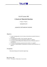
The forming process impact extrusion is defined in DIN 8583, part 6, as follows (Figure<br />
<strong>3502</strong>.01.01):<br />
Impact extrusion is the pressing out of a work-piece (e.g. rod section, sheet<br />
sections) placed between tool parts, through an orifice with the help of a<br />
punch. It is used mainly to produce single components.<br />
Impact extrusion is an important bulk forming process and offers a range of special<br />
advantages, like:<br />
− optimal usage of material<br />
− high production rates with short piece-production times<br />
− accurate reproduction of dimensions and forms coupled with a good surface<br />
quality<br />
− good static and dynamic properties of the components due to the favourable<br />
fibre structure and work hardening.<br />
<strong>TALAT</strong> <strong>3502</strong> 2
Source: DIN 8583, part 6<br />
Definition of Impact Extrusion<br />
Impact extrusion is the pressing out of a work-piece<br />
(e.g. rod sections, sheet sections) placed between tool<br />
parts, mainly to produce single components.<br />
Unlike tapering, impact extrusions offer larger degrees<br />
of deformation.<br />
alu<br />
Definition of Impact Extrusion <strong>3502</strong>.01.01<br />
Training in Aluminium Application Technologies<br />
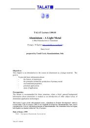
Figure <strong>3502</strong>.01.02 and Figure <strong>3502</strong>.01.03 show typical impact extruded parts. Impact<br />
extrusion is particularly suitable for the fabrication of parts which, with the exception of<br />
some additional local machining, are in their near-net-shape condition.<br />
alu<br />
Training in Aluminium Application Technologies<br />
Impact Extruded Parts - I<br />
<strong>TALAT</strong> <strong>3502</strong> 3<br />
Impact Extruded Parts - I <strong>3502</strong>.01.02<br />
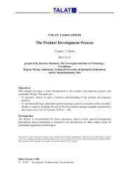
The geometric forms which can be impact extruded are limited mainly to axially<br />
symmetrical cross sections, in particular with rotational symmetry. Such parts may<br />
contain interior forms which are axially symmetrical or sometimes even unsymmetrical<br />
to a limited extent. The required wall thickness is a decisive criteria for the feasibility of<br />
fabricating a certain form. Using appropriate tooling techniques and technologies of<br />
impact extrusion, it is possible to fabricate components with laterally extending
elements.<br />
Training in Aluminium Application Technologies<br />
Tool:<br />
alu<br />
alu<br />
Training in Aluminium Application Technologies<br />
Impact Extruded Parts - II<br />
<strong>TALAT</strong> <strong>3502</strong> 4<br />
Impact Extruded Parts - II <strong>3502</strong>.01.03<br />
Classification of Impact Extrusion Processes<br />
- impact extrusion with<br />
rigid tools<br />
- impact extrusion with<br />
movable tools<br />
Source: DIN 8583, part 6<br />
Classification<br />
according to<br />
Work-piece geometry:<br />
- solid impact extrusion<br />
- hollow impact extrusion<br />
- cup impact extrusion<br />
- flange impact extrusion<br />
(only for lateral impact<br />
extrusion)<br />
Direction of material<br />
flow relative to the<br />
working direction:<br />
- forward impact extrusion<br />
- backward impact extrusion<br />
- Lateral impact extrusion<br />
Classification of Impact Extrusion Processes <strong>3502</strong>.01.04<br />
Figure <strong>3502</strong>.01.04 shows the classification of impact extrusion processes. According to<br />
DIN 8583, impact extrusion, together with tapering and extrusion, belongs to the<br />
fabrication processes of „pressing through orifices“ in the main group of „forming by
compressive forces“. The impact extrusion processes can be further sub-divided as<br />
follows:<br />
− according to the type of tool in:<br />
impact extrusion with rigid (immovable) tools and impact extrusion with an<br />
active medium, which plays a role only for special products;<br />
− according to the direction of material flow relative to the working direction<br />
of the machine in:<br />
forwards, reverse and lateral impact extrusion;<br />
− according to the work-piece geometry in:<br />
full, hollow and cup impact extrusion as well as flange impact extrusion<br />
(only for lateral impact extrusion);<br />
These basic process variations of impact extrusion are used in combinations among<br />
themselves as well as with other bulk forming operations like compressing, upsetting,<br />
form pressing, stamping, tapering and drawing. All impact extrusion operations can be<br />
conducted at room temperature (cold impact extrusion) as well as by heating to a higher<br />
operating temperature, depending on material and process specifications (semi-hot and<br />
hot impact extrusion).<br />
<strong>3502</strong>.02 Fundamentals<br />
Impact extrusion is based on the ability of crystals to glide by slip under certain stresses<br />
without destroying the cohesion between the slip planes. In order to be able to cause the<br />
crystal structure to form under impact extrusion, the resulting shear stresses or principal<br />
stress difference must exceed a certain critical value. This value is generally called the<br />
flow stress, k f .<br />
The change in dimensions of a body during forming is called strain which is referred<br />
either to the original dimensions, l o , b o , h o or to the instant dimensions, li, bi or hi.<br />
For impact extrusion the<br />
are usually used.<br />
conventional or engineering strain : ε A = ∆A / A o<br />
(reduction in area) where ∆A = (Ai - A o )<br />
and the natural or true strain: ϕ A = ln(Ai/A o )<br />
(logarithmic strain) = ln(1 + ε A )<br />
<strong>TALAT</strong> <strong>3502</strong> 5
<strong>3502</strong>.03 Impact Extrusion with Quasi-stationary Material Flow<br />
Process steps<br />
The basic processes „solid forwards, solid backwards“, „hollow forwards and hollow<br />
backwards“ all belong to the impact extrusion process with quasi-stationary material<br />
flow, which means that on the whole, deformation is distributed homogeneously across<br />
the cross-section of the work-piece, a few locally limited exceptions being possible. The<br />
forward impact extrusion process is most widely used.<br />
Figure <strong>3502</strong>.03.01 illustrates the operational steps during „solid forward“ impact<br />
extrusion. The material is first pressed into the holder so that it fills out the cavity. The<br />
continued stroke of the punch then causes the material to be pressed out of the die. The<br />
deformation and flow zone builds up directly in front of the die opening. In the initial<br />
stage of forming the process is non-stationary. With the volume of material leaving the<br />
forming zone through the die opening at constant punch speed the process changes to a<br />
quasi-stationary forming process. Thus, quasi-stationary states of deformation and<br />
deformation speed are created. After completion of the forming operation, the workpiece<br />
is removed by a knockout or ejector mechanism.<br />
Source: K.Siegert<br />
alu<br />
Training in Aluminium Application Technologies<br />
Operation Steps during Solid Forward<br />
Impact Extrusion<br />
a) b) c) d)<br />
a) Inserting the slug<br />
b) Compressing the slug<br />
<strong>TALAT</strong> <strong>3502</strong> 6<br />
Pressing punch<br />
Work-piece<br />
Holder (container)<br />
Ejector punch<br />
Die<br />
c) Impact extrusion<br />
d) Ejecting finished part<br />
Operation Steps during Solid Forward Impact Extrusion <strong>3502</strong>.03.01<br />
Figure <strong>3502</strong>.03.02 illustrates the operation steps during „solid backward“ impact<br />
extrusion. During the „solid backward“ extrusion operation, the die and punch build a<br />
single unit. The bottom of the holder is closed by an ejector punch. During the forming<br />
process, the die moves into the holder. Following the initial compression period, the<br />
material is pressed through the die into the hollow punch cavity.
a) b) c) d)<br />
Source: K.Siegert<br />
alu<br />
Training in Aluminium Application Technologies<br />
Operation Steps during Solid Backward<br />
Impact Extrusion<br />
a) Inserting the slug<br />
b) Compressing the slug<br />
Operation Steps during Solid Backward<br />
Impact Extrusion<br />
<strong>TALAT</strong> <strong>3502</strong> 7<br />
Pressing punch with<br />
die head<br />
Work-piece<br />
Holder (container)<br />
Ejector punch<br />
c) Impact extrusion<br />
d) Ejecting the finished part<br />
<strong>3502</strong>.03.02<br />
Figure <strong>3502</strong>.03.03 shows the operational steps during „hollow forward“ impact<br />
extrusion. A shell (or cup) is formed into a shell with reduced wall thickness. The<br />
contours of the impact are created by the internal contours of a shaped punch.<br />
Source: K.Siegert<br />
a) Inserting the slug<br />
b) Compressing the slug<br />
alu<br />
Training in Aluminium Application Technologies<br />
Operation Steps during Hollow Forward<br />
Impact Extrusion<br />
a) b) c) d)<br />
Operation Steps during Hollow<br />
Forward Impact Extrusion<br />
Pressing punch<br />
Work-piece<br />
Holder (container)<br />
Ejector punch<br />
Die<br />
c) Impact extrusion<br />
d) Ejecting the finished part<br />
<strong>3502</strong>.03.03<br />
There are four different ways to design a punch for hollow impact extrusions which are
shown in Figure <strong>3502</strong>.03.04, Figure <strong>3502</strong>.03.05 and Figure <strong>3502</strong>.03.06.<br />
Source: K.Siegert<br />
alu<br />
Training in Aluminium Application Technologies<br />
Punch Design for Hollow Impact Extrusion - I<br />
Integrated mandrel<br />
Punch Design for Hollow Impact Extrusion - I<br />
<strong>TALAT</strong> <strong>3502</strong> 8<br />
Pressing punch<br />
Integrated mandrel<br />
Work-piece<br />
Holder with die<br />
<strong>3502</strong>.03.04<br />
Figure <strong>3502</strong>.03.04 illustrates the „integrated mandrel“: The integrated mandrel is the<br />
simplest design, but is subjected to unfavourable stresses and notch effects due to the<br />
large change in cross-section.<br />
Integrated<br />
mandrel<br />
Source: K.Siegert<br />
alu<br />
Training in Aluminium Application Technologies<br />
Punch Design for Hollow Impact Extrusion - II<br />
Pressing punch<br />
Work-piece<br />
Holder with die<br />
Spring<br />
Inserted mandrel Coupled-motion mandrel<br />
Coupled-motion<br />
punch<br />
Punch Design for Hollow Impact Extrusion - II <strong>3502</strong>.03.05<br />
Figure <strong>3502</strong>.03.05 shows the „inserted mandrel“ (left). It is a more favourable solution<br />
which takes account of the differing operating lives of mandrel and punch. The „moving<br />
mandrel“ (right) is supported by a spring in order to reduce the friction between mandrel
and work-piece. The mandrel moves together with the work-piece during forming.<br />
Source: K.Siegert<br />
Punch Design for Hollow Impact Extrusion - III<br />
alu<br />
Training in Aluminium Application Technologies<br />
Stationary mandrel<br />
<strong>TALAT</strong> <strong>3502</strong> 9<br />
Pressing punch<br />
Work-piece<br />
Holder with die<br />
Ejector punch<br />
Stationary mandrel<br />
Base plate<br />
Ejector pin (3x)<br />
Punch Design for Hollow Impact Extrusion - III <strong>3502</strong>.03.06<br />
Figure <strong>3502</strong>.03.06 shows the „stationary mandrel“: This design has the advantage of a<br />
well-guided mandrel, but, at the same time, has more unfavourable friction<br />
characteristics.<br />
Pressing punch<br />
with die head<br />
Work-piece<br />
Stationary<br />
mandrel<br />
Holder<br />
Ejector punch<br />
Source: K. Siegert<br />
alu<br />
Training in Aluminium Application Technologies<br />
Operation steps during hollow<br />
backward impact extrusion<br />
a) Inserting the b) Compressing the<br />
raw work-piece raw work-piece<br />
Operation steps during hollow<br />
backward impact extrusion<br />
c) Impact<br />
extrusion<br />
d) Ejecting<br />
finished part<br />
<strong>3502</strong>.03.07<br />
Figure <strong>3502</strong>.03.07 illustrates the operational steps during „hollow backward“ impact<br />
extrusion. Both „hollow forward“ impact extrusion and „hollow backward“ impact<br />
extrusion have, in principle, the same process steps with the exception that in „hollow<br />
forward“ extrusion, the contours of the stationary mandrel in the ejector punch are
esponsible for the interior contours of the work-piece. In „hollow backward“ impact<br />
extrusion the ejector punch tool is fitted with three ejector pins which lift the punch at<br />
the end of the operation. The pins are activated hydraulically or mechanically to carry<br />
out the ejecting operation, see Figure <strong>3502</strong>.03.08.<br />
Source: K. Siegert<br />
alu<br />
Training in Aluminium Application Technologies<br />
Material Flow and Deformation<br />
Hollow backward impact extrusion<br />
<strong>TALAT</strong> <strong>3502</strong> 10<br />
Ejector in punch<br />
Pressing punch with die<br />
Work-piece<br />
Holder<br />
Mandrel<br />
Ejector punch<br />
Base plate<br />
Bottom plate<br />
Ejector pin (3x)<br />
Ejector activator<br />
Hollow Backward Impact Extrusion<br />
<strong>3502</strong>.03.08<br />
Figure <strong>3502</strong>.03.09 and Figure <strong>3502</strong>.03.10 show the material flow during „solid<br />
forward“ impact extrusion. At the beginning, the forming process is non-stationary till<br />
the orifice is completely filled with material. The non-stationary region is indicated by<br />
the distorted grid lines. The volume elements of the material are axially compressed and<br />
radially expanded. The non-stationary pressing operation causes the material to bulge at<br />
the end and to be pressed outward (Figure <strong>3502</strong>.03.09)<br />
The stationary region that follows is characterised by a uniform deformation strain and a<br />
uniform distortion of the volume elements. The vertical grid lines are parallel to the axis<br />
and the total deformation of an element is less than in the nonstationary region. If the die<br />
opening angle is large (2α > 120 °), so-called "dead material zones", which do not<br />
participate in the main flow, are created behind the flowing material. The material flow<br />
in the „hollow forward“ impact extrusion behaves similar to the „solid forward“ impact<br />
extrusion but has a smaller displaced part during the movement of the material into the<br />
forming zone.
Source: IfU Stuttgart<br />
alu<br />
Training in Aluminium Application Technologies<br />
Material flow during full forward impact extrusion<br />
s = 0 mm<br />
FEM results - part I<br />
s - punch distance moved<br />
<strong>TALAT</strong> <strong>3502</strong> 11<br />
Material Flow during Full Forward Impact Extrusion<br />
FEM Results - Part I<br />
Material flow during full forward impact extrusion<br />
s = 10 mm<br />
<strong>3502</strong>.03.09<br />
FEM results - part II<br />
s = 15 mm s = 20 mm<br />
Source: IfU Stuttgart<br />
alu<br />
Training in Aluminium Application Technologies<br />
s - punch distance moved<br />
Material Flow during Full Forward Impact Extrusion<br />
FEM Results - Part II<br />
<strong>3502</strong>.03.10<br />
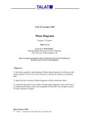
Figure <strong>3502</strong>.03.11 shows the results of calculations of comparative strain during „solid<br />
forward“ impact extrusion. The comparative strain (deformation) during solid forward<br />
impact extrusion reaches a maximum value in the region of the die opening plane and<br />
decreases, the further one moves radially into the interior of the work-piece. The large<br />
change in the comparative strain distribution in the radial direction decreases with<br />
increasing reduction of cross-section.
Stresses<br />
Comparative Strain During Forward Impact Extrusion<br />
Material:AlMgSi1-T4<br />
Punch movement: 20 mm<br />
εa - Reduction in cross-sectional area<br />
Source: IFU Stuttgart<br />
εA = 40 % εA = 60 % εA = 75 %<br />
0.30<br />
alu<br />
Training in Aluminium Application Technologies<br />
0.45<br />
0.30<br />
0.45<br />
0.60<br />
0.75<br />
0.90<br />
1.50<br />
1.35<br />
1.20<br />
1.05<br />
0.90<br />
0.75<br />
0.60<br />
Comparative Strain During Forward Impact Extrusion <strong>3502</strong>.03.11<br />
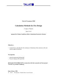
Stresses during solid forward impact extrusion are described in Figure <strong>3502</strong>.03.12.<br />
<strong>TALAT</strong> <strong>3502</strong> 12<br />
0.75<br />
0.30<br />
0.45<br />
0.60<br />
0.75<br />
0.90<br />
1.50<br />
1.35<br />
1.20<br />
1.05<br />
0.90<br />
Stresses during solid forward impact extrusion<br />
A 0<br />
α<br />
0<br />
z<br />
d 0<br />
d 1<br />
F tot<br />
σt<br />
Source: R. Geiger / R. Woska<br />
alu<br />
Training in Aluminium Application Technologies<br />
1<br />
r<br />
FRW σz<br />
A 1<br />
σr<br />
F RS<br />
kf0, kf1 - Flow stresses<br />
Ftot - Forming force<br />
FRS - Frictional force at<br />
impact extrusion<br />
"shoulders"<br />
FRW - Frictional force at<br />
press sleeve walls<br />
z<br />
l<br />
1.05<br />
1.50<br />
1.35<br />
1.20<br />
1.05<br />
0.30<br />
0.45<br />
0.60<br />
0.75<br />
0.90<br />
Stresses During Solid Forward Impact Extrusion <strong>3502</strong>.03.12<br />
σz<br />
k f1<br />
Tension σz - σr = kf Compression<br />
k f0<br />
σr - Radial stress<br />
σt - Tangential stress<br />
σz - Axial stress<br />
0, 1 - Boundaries of<br />
forming region<br />
σr ~<br />
σt
The forming force Ftot is applied through the punch. The deformation zone extends<br />
from plane 0, where the material is plastic, to plane 1. At the outlet of the opening, the<br />
material moves out without constraint so that the axial stress, σz = 0. From this plane<br />
onward, the axial stress increases in the strained zone as a compressive stress up to the<br />
plane 0 and attains the value σz0 = Ftot/A0. The principal stresses in the radial, σr and<br />
in the tangential, σt direction are equal. According to Tresca: σr = σz - kf<br />
During hollow forward impact extrusion, a similar complex (3-dimensional) state of<br />
compressive stress with σr, σz and σt exists. The radial stress σr is the largest<br />
compressive stress. For thick-walled hollow bodies σr ≈ σt, for thin-walled ones σt ≈<br />
(σz + σr)/2.<br />
Force-Distance Curve<br />
Figure <strong>3502</strong>.03.13 illustrates a typical force-distance curve for a quasi-stationary impact<br />
extrusion operation using the solid forward impact extrusion process as an example.<br />
There is a rapid linear rise of the punch force due to the elastic deformation in the<br />
system tool - work-piece (region 1). The work-piece is pressed into the opening and<br />
deformed plastically. The maximum force attained is a result of both the deformation of<br />
the work-piece elements as well as the transition of the friction from static to dynamic at<br />
the impact extrusion "shoulder". The work against friction (AR2) between the holder<br />
(container) and work-piece decreases with increasing deformation so that the force starts<br />
to drop. The deformation force, the frictional force between die walls and work-piece<br />
over the stroke as well as the frictional force between punch and container over the<br />
stroke remain constant during the stationary deformation process.<br />
F st<br />
F 1<br />
F 2<br />
1<br />
P 1<br />
alu<br />
Training in Aluminium Application Technologies<br />
2<br />
P 2<br />
S1 S2 Distance travelled by press punch, S<br />
Source: K. Siegert<br />
Force-distance curve during<br />
solid forward impact extrusion<br />
<strong>TALAT</strong> <strong>3502</strong> 13<br />
3<br />
4<br />
1 - Nonstationary forming process<br />
"compressing" and<br />
"pressing through"<br />
2 - Energy A R2 required to overcome<br />
friction between work-piece<br />
and holder<br />
3 - Forming energy and energy A R3<br />
for overcoming friction between<br />
die walls and work-piecel<br />
4 - Energy A R4 for overcoming friction<br />
between pressing punch and holder<br />
Force-distance Curve during Solid Forward Impact Extrusion <strong>3502</strong>.03.13
The force-distance curves for „solid backward“ impact extrusion are similar to those for<br />
„solid forward“ impact extrusion with the exception that the frictional energy AR1<br />
required to move the work-piece in the holder does not have to be considered, see<br />
Figure <strong>3502</strong>.03.14.<br />
F st<br />
F 1,2<br />
1<br />
alu<br />
Training in Aluminium Application Technologies<br />
P 1<br />
S 1<br />
Distance travelled by press punch, S<br />
Source: K. Siegert<br />
Force-distance curve during<br />
solid backward impact extrusion<br />
<strong>TALAT</strong> <strong>3502</strong> 14<br />
2<br />
3<br />
P 2<br />
S 2<br />
1 - Nonstationary forming process<br />
"compressing" and<br />
"pressing through"<br />
2 - Forming energy and energy A R2<br />
for overcoming friction between<br />
die walls and work-piece<br />
3 - Energy A R3 for overcoming friction<br />
between pressing punch and holder<br />
Force-distance Curve During Solid Backward Impact Extrusion <strong>3502</strong>.03.14<br />
The force-distance curve for hollow impact extrusions is, in principle, similar to that for<br />
solid impact extrusions, with the exception that the frictional force acting between<br />
forming material and punch or between forming material and mandrel has also to be<br />
considered.<br />
<strong>3502</strong>.04 Impact Extrusion with Non-stationary Material Flow<br />
Process Steps<br />
The basic processes cup forward, cup backward and lateral impact extrusion belong to<br />
the impact extrusion operations with nonstationary material flow, whereby the cup<br />
backward impact extrusion is the one more commonly used.<br />
Figure <strong>3502</strong>.04.01 illustrates the process steps of the „cup forward“ impact extrusion<br />
The „cup forward“ impact extrusion differs from the solid forward impact extrusion in<br />
that the actual die is composed of the holder (container) and an immovable mandrel<br />
which together cause the work-piece material to replicate the interior contours of the<br />
cup.
Training in Aluminium Application Technologies<br />
Process Steps of the Cup Forward<br />
Impact Extrusion<br />
a) b) c) d)<br />
Source: K. Siegert<br />
alu<br />
a) Inserting the raw work-piece<br />
b) Compressing the raw work-piece<br />
Process Steps of the Cup Forward Impact Extrusion <strong>3502</strong>.04.01<br />
<strong>TALAT</strong> <strong>3502</strong> 15<br />
Pressing punch<br />
Work-piece<br />
Ejector punch<br />
Holder<br />
Stationary mandrel<br />
c) Impact extrusion<br />
d) Ejecting finished part<br />
In the cup backward impact extrusion the punch is forced into the forming material<br />
which is radially enclosed by the holder (container). An ejector punch builds the bottom<br />
of the container, see Figure <strong>3502</strong>.04.02.<br />
a) Inserting the raw work-piece<br />
b) Compressing the raw work-piece<br />
Source: K. Siegert<br />
alu<br />
Training in Aluminium Application Technologies<br />
Process Steps of the<br />
Cup Backward Impact Extrusion<br />
a) b) c) d)<br />
c) Impact extrusion<br />
d) Ejecting finished part<br />
Punch<br />
Work-piece<br />
Holder<br />
Ejector punch<br />
Process Steps of the Cup Backward Impact Extrusion <strong>3502</strong>.04.02<br />
Figure <strong>3502</strong>.04.03 shows the process steps during „solid lateral“ impact extrusion. The<br />
term lateral impact extrusion is applied to cover processes in which the material flows at
an angle (mostly 90 °) to the direction of movement of the punch. As opposed to<br />
compression in which similar forms can be created, the forming orifices remain here<br />
unchanged during the process. During lateral impact extrusion, the local deformation<br />
strain can reach values of up to εv = 5. In order to create the lateral form elements, an<br />
additional vertical or horizontal splitting of the tool is necessary, together with a tool<br />
closing action coupled to the punch movement. For this purpose a multi-acting toolmachine<br />
system is necessary.<br />
„Solid lateral“ impacts with pegs at 90° to the punch movement direction can be<br />
extruded using a transversely split container with a die arranged at right angles in the<br />
splitting (parting) plane. The pressing punches in the container halves, penetrate at the<br />
same speed, so that a pressing action, symmetrical to the splitting plane, is attained.<br />
alu<br />
Training in Aluminium Application Technologies<br />
Process Steps of Solid<br />
Lateral Impact Extrusion<br />
a) b) c) d)<br />
Source: K. Siegert<br />
a) Inserting the raw work-piece<br />
b) Compressing the raw work-piece<br />
<strong>TALAT</strong> <strong>3502</strong> 16<br />
c) Impact extrusion<br />
d) Ejecting finished part<br />
Pressing punch<br />
Holder with die-half<br />
Work-piece<br />
Holder with die-half<br />
Counter punch<br />
Process Steps of Solid Lateral Impact Extrusion <strong>3502</strong>.04.03<br />
Figure <strong>3502</strong>.04.04 shows the process steps during the „cup lateral“ impact extrusion.<br />
In the „cup lateral“ impact extrusion process, rigid mandrels are arranged in the splitting<br />
(parting) plane at right angles to the direction of punch movement. At the end of the<br />
impact extrusion process, these mandrels can be pulled radially out of the work-piece<br />
using mechanical or hydraulic systems. The actual tool can now be opened to remove<br />
the finished part.
alu<br />
Training in Aluminium Application Technologies<br />
Process Steps of the<br />
Cup Lateral Impact Extrusion<br />
a) b) c) d) e)<br />
Source: K. Siegert<br />
a) Inserting the raw work-piece<br />
b) Compressing the raw work-piece<br />
c) Impact extrusion<br />
d) Retracting the mandrels<br />
e) Ejecting finished part<br />
<strong>TALAT</strong> <strong>3502</strong> 17<br />
1 Punch<br />
2 Work-piece<br />
3 Holder with die-half<br />
4 Holder with die-half<br />
5 Counter punch<br />
6 Mandrel<br />
Process Steps of the Cup Lateral Impact Extrusion <strong>3502</strong>.04.04<br />
Process steps during the lateral impact extrusion of a flange or collar are shown in<br />
Figure <strong>3502</strong>.04.05. The process steps during the lateral impact extrusion of a flange or<br />
collar are, in principle, same as those for the solid lateral impact extrusion, with the<br />
difference that the die is hollowed out at the circumference of the splitting plane, so that<br />
a flange or collar can be formed during pressing.<br />
a)<br />
Source: IFU Stuttgart<br />
Training in Aluminium Application Technologies<br />
Process Steps of Lateral Impact Extrusion<br />
of a Flange or Collar<br />
alu<br />
b) c)<br />
a) Inserting the raw work-piece<br />
b) Compressing the raw work-piece<br />
d)<br />
Process Steps of Lateral Impact Extrusion<br />
of a Flange or Collar<br />
c) Impact extrusion<br />
d) Ejecting finished part<br />
5<br />
1<br />
3<br />
2<br />
Pressing punch<br />
4<br />
Holder with die-half<br />
Work-piece<br />
Holder with die-half<br />
Counter punch<br />
6<br />
<strong>3502</strong>.04.05
Material Flow and Deformation<br />
Material flow during „cup backward“ impact extrusion is illustrated in Figure<br />
<strong>3502</strong>.04.06. During the penetration of the punch in the „cup backward“ impact<br />
extrusion, the material is first subjected to an axial compression which causes it to be<br />
pressed radially outward to the container walls and then to flow up against the direction<br />
of the punch movement, through the ring-formed orifice between punch and container.<br />
The material flows initially along the walls but may flow freely later-on. The ringformed<br />
orifice corresponds to the wall thickness of the cup. Under the influence of the<br />
punch force, the forming material builds a hemispherical plastic region under the punch.<br />
The extent of this strained region depends on the geometrical conditions of the process<br />
like relative change in cross-section and base thickness of the cup. Due to the<br />
nonhomogeneous deformation process, the true deformation strain can only be<br />
approximately calculated by the equation ϕg = ln (A0/Al).<br />
According to Dipper:<br />
ϕm = ϕ1(di/do)² + ϕ2(do²-di²)/do²<br />
with the main strains ϕ 1 = ln(l o /b)<br />
ϕ2 = ϕ1 [1 + (di /8s)]<br />
Usually one uses the reduction in area as the comparative characteristic value<br />
ε A = (A 0 - A 1 )/A 0<br />
The distribution of the comparative strain for the cup backward impact extrusion is<br />
clearly nonhomogeneous, which means that we are clearly dealing with an nonstationary<br />
process. The largest strain occurs at the no-slip point. A double-sided application of<br />
force causes the material to flow most uniformly in the secondary form elements,<br />
because no motionless material regions and no abrupt speed gradients occur.<br />
Illustration using a grid<br />
Source: R. Geiger / R. Woska<br />
alu<br />
Training in Aluminium Application Technologies<br />
Material Flow during<br />
Cup Backward Impact Extrusion<br />
<strong>TALAT</strong> <strong>3502</strong> 18<br />
d i<br />
Material Flow during Cup Backward Impact Extrusion<br />
s<br />
b<br />
<strong>3502</strong>.04.06
Stresses<br />
A three-dimensional state of compressive stress exists also during the „cup backward“<br />
impact extrusion. Because of the strongly non-homogeneous straining, determining the<br />
local stresses is highly complicated. A model process is used as a basis for determining<br />
the stresses analytically. In Dipper's model, the „cup backward“ impact extrusion is<br />
assumed to be a double compression process.<br />
Figure <strong>3502</strong>.04.07 shows the stresses in the „cup backward“ impact extrusion process.<br />
The starting slug is first compressed between the punch of diameter di and the die<br />
bottom (zone 1). The material which is pressed outwards reaches the die walls and is<br />
compressed once more to deliver the required wall thickness (zone 2). The material<br />
which is pressed through the ring-formed orifice between punch and container (zone 3)<br />
is considered to be motionless. This assumption is valid for thin-walled cups with εA ≥<br />
0.5. Both compression processes are considered to be homogeneous deformation<br />
processes.<br />
Stresses during<br />
cup backward<br />
impact extrusion<br />
Source: R. Geiger / R. Woska<br />
alu<br />
Training in Aluminium Application Technologies<br />
<strong>TALAT</strong> <strong>3502</strong> 19<br />
Stresses during Cup Backward Impact Extrusion<br />
<strong>3502</strong>.04.07<br />
Radial and axial compressive stresses as well as tangential stresses occur during the<br />
lateral impact extrusion of flanges and collars. When the tangential stress exceeds the<br />
flow stress, necking and cracking occur in the flange.<br />
When laterally extending form elements are lateral impact extruded, the state of stress<br />
can be defined as being compressive.
Force-Distance Curves<br />
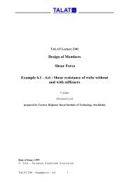
Figure <strong>3502</strong>.04.08 illustrates a characteristic force-distance curve for a cup impact<br />
extrusion. On the whole, this corresponds to the curve for punch force as a function of<br />
punch stroke during „solid backward“ impact extrusion. The measured punch force, FSt<br />
rises rapidly up to a maximum value which is reached when the punch penetrates into<br />
the forming material, and then remains almost constant or falls slightly. For large εA<br />
values, a peak force value is attained at the beginning, corresponding to the transition of<br />
friction from static to dynamic. The maximum force, Fst max increases with increasing<br />
kf, εA and do. In the range 0.15 < εA < 0.6, it depends additionally on the ratio lo/do.<br />
When the remaining bottom thickness, b, is very small, a small increase of force is<br />
observed. This is mainly a result of the increasing axial compressive force.<br />
The „cup forward“ impact extrusion process has higher frictional losses in the press die<br />
and, therefore, requires higher forces than the cup backward impact extrusion process.<br />
Source: K. Lange<br />
alu<br />
Training in Aluminium Application Technologies<br />
Punch force, FSt<br />
350<br />
<strong>TALAT</strong> <strong>3502</strong> 20<br />
kN<br />
300<br />
250<br />
200<br />
150<br />
100<br />
50<br />
<strong>3502</strong>.05 Combined Processes<br />
l 0<br />
d i<br />
F St<br />
d 0<br />
h St<br />
b<br />
Material: AlZnMgCu1,5<br />
Zinc phosphate + sodium soap<br />
Dimensions: d 0 = 28mm<br />
l 0/d 0 = 1,0<br />
d i = 20mm<br />
0 5 10 15 20 25 mm 30<br />
Distance travelled by punch, hST Force-distance Curve for a<br />
Cup Backward Impact Extrusion Process<br />
<strong>3502</strong>.04.08<br />
The following figures illustrate the various combinations of the basic impact extrusion<br />
processes, in order to achieve a multitude of section shapes:<br />
Figure <strong>3502</strong>.05.01: Combined „solid forward“ and „cup backward“ impact extrusion<br />
Figure <strong>3502</strong>.05.02: Combined „cup forward“ and „cup backward“ impact extrusion<br />
Figure <strong>3502</strong>.05.03: Combined „cup backward“ impact extrusion
Figure <strong>3502</strong>.05.04: Combined „solid backward“ and „cup backward“ impact extrusion<br />
Figure <strong>3502</strong>.05.05: Combined „lateral“ and „cup forward“ impact extrusion<br />
Figure <strong>3502</strong>.05.06: Combined processes - I<br />
Figure <strong>3502</strong>.05.07: Combined processes - II<br />
Source: K. Lange<br />
alu<br />
Training in Aluminium Application Technologies<br />
Source: K. Lange<br />
Combined solid forward and<br />
cup backward impact extrusion<br />
Start of process<br />
alu<br />
Training in Aluminium Application Technologies<br />
<strong>TALAT</strong> <strong>3502</strong> 21<br />
Combined Solid Forward and<br />
Cup Backward Impact Extrusion<br />
End of process<br />
Combined Cup Forward and Cup Backward<br />
Impact Extrusion<br />
Start of Process End of Process<br />
Combined Cup Forward and Cup Backward<br />
Impact Extrusion<br />
<strong>3502</strong>.05.01<br />
<strong>3502</strong>.05.02
Source: K. Lange<br />
alu<br />
Training in Aluminium Application Technologies<br />
Source: K. Lange<br />
Combined cup backward impact extrusion<br />
Start of process End of process<br />
alu<br />
Training in Aluminium Application Technologies<br />
<strong>TALAT</strong> <strong>3502</strong> 22<br />
Combined Cup Backward Impact Extrusion<br />
Combined Solid Backward and Cup Backward<br />
Impact Extrusion<br />
Start of Process End of Process<br />
Combined Solid Backward and Cup Backward<br />
Impact Extrusion<br />
<strong>3502</strong>.05.03<br />
<strong>3502</strong>.05.04
Source: K. Lange<br />
alu<br />
Training in Aluminium Application Technologies<br />
Source: Aluminium-Zentrale<br />
Start of Process End of Process<br />
alu<br />
Training in Aluminium Application Technologies<br />
Combined Lateral and Cup Forward<br />
Impact Extrusion<br />
Combined Lateral and Cup Forward<br />
Impact Extrusion<br />
Combined Processes - I<br />
Backward hollow with forward solid impact extrusion<br />
<strong>TALAT</strong> <strong>3502</strong> 23<br />
Shells with massive base external shaft, e.g. condenser cups<br />
are fabricated according to this process variation.<br />
<strong>3502</strong>.05.05<br />
Backward hollow with forward hollow impact extrusion<br />
Shells with intermediate bases are mostly fabricated<br />
using this process variation.<br />
The two shell parts may have different diameters.<br />
Backward solid with forward hollow impact extrusion<br />
Shells with collar and external shaft are fabricated using<br />
this process variation.<br />
Combined Processes - I <strong>3502</strong>.05.06
Source: Aluminium-Zentrale<br />
alu<br />
Training in Aluminium Application Technologies<br />
Combined Processes - II<br />
Backward hollow with backward solid impact extrusion<br />
Used, for example, for shells with massive internal shafts.<br />
Backward hollow with backward hollow impact extrusion<br />
This process is used to fabricate shells with hollow internal<br />
shafts or for multi-walled shells.<br />
Backward solid with forward solid impact extrusion<br />
Massive parts, e.g. shafts with collars, can be made<br />
using this process.<br />
<strong>TALAT</strong> <strong>3502</strong> 24<br />
Combined Processes - II <strong>3502</strong>.05.07<br />
A difference is made here between processes which occur sequentially and those which<br />
occur simultaneously.<br />
In processes which occur sequentially, the material flow is controlled by the movements<br />
of the active (movable) parts.<br />
In processes which occur simultaneously, the material can flow simultaneously through<br />
different orifices, so that the geometry of the newly formed part cannot be precalculated<br />
solely on the basis of the dimensions of the starting slug, the tool geometry, and the law<br />
of volume constancy. The material flow in such processes is, therefore uncontrolled.<br />
Forming by using process combinations in which the material flow is uncontrolled leads<br />
to problems, because the flow lengths and forces required cannot be precalculated with<br />
any measure of accuracy.<br />
The material in a combined forming process can only flow in different directions when<br />
the resistance to flow in these directions is the lowest (principle of the lowest<br />
resistance).<br />
Material flow in the combined „solid forward“ and „cup backward“ impact extrusion is<br />
illustrated in Figure <strong>3502</strong>.05.08. During the simultaneous flow of material in different<br />
directions and depending on the geometrical conditions, a no-slip point is created. If the<br />
material flow in one direction encounters a hindrance or is stopped, the no-slip point<br />
moves in the direction of the hindered material flow or disappears.
Material: Al 99,5<br />
Punch Movement: 30%<br />
d a/d i = 1.025<br />
Source: IfU Stuttgart<br />
Material Flow in the Combined Solid Forward and<br />
Cup Backward Impact Extrusion<br />
alu<br />
Training in Aluminium Application Technologies<br />
FEM Results<br />
Material Flow in the Combined Solid Forward and Cup<br />
Backward Impact Extrusion<br />
<strong>TALAT</strong> <strong>3502</strong> 25<br />
<strong>3502</strong>.05.08<br />
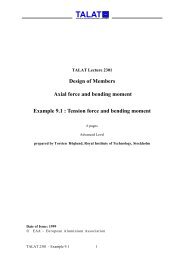
Figure <strong>3502</strong>.05.09 shows the force-distance curve during combined processes. The<br />
force required for all combined processes in which simultaneous unhindered flow<br />
occurs, is smaller or at the most equal to the force needed for the process which requires<br />
the lower force. For different relative cross-sectional strains, ε A , in the partial processes,<br />
the total force required for the combined process is equal to the force requirement for<br />
the partial process with lower ε A .The forming process is self-controlling. At any<br />
moment of time, a minimum of forming power is required.<br />
Force-Distance Curves for Combined Processes<br />
Comparison of the Combined Cup Impact Extrusion<br />
Source: K. Lange<br />
Punch Force, FSt<br />
alu<br />
Training in Aluminium Application Technologies<br />
350<br />
kN<br />
300<br />
250<br />
200<br />
150<br />
100<br />
50<br />
with the Basic Processes<br />
Cup Forward Impact Extrusion<br />
Cup Backward Impact Extrusion<br />
Combined Cup Impact Extrusion<br />
0 5 10 15 20 25 mm 30<br />
Stroke of Punch, h St<br />
Force-Distance Curves for Combined Processes<br />
d i1<br />
di2 d0 F St<br />
hSt<br />
l0<br />
Material: AlZnMgCu1,5<br />
Zinc phosphate + sodium soap<br />
Dimensions : d 0 = 28mm<br />
l 0 / d 0 = 1.0<br />
d i1 = d i2 = 20 mm<br />
<strong>3502</strong>.05.09
<strong>3502</strong>.06 List of Figures<br />
Figure No. Figure Title (Overhead)<br />
<strong>3502</strong>.01.01 Definition of Impact Extrusion<br />
<strong>3502</strong>.01.02 Impact Extruded Parts - I<br />
<strong>3502</strong>.01.03 Impact Extruded Parts - II<br />
<strong>3502</strong>.01.04 Classification of Impact Extrusion Processes<br />
<strong>3502</strong>.03.01 Operation Steps during Solid Forward Impact Extrusion<br />
<strong>3502</strong>.03.02 Operation Steps during Solid Backward Impact Extrusion<br />
<strong>3502</strong>.03.03 Operation Steps during Hollow Forward Impact Extrusion<br />
<strong>3502</strong>.03.04 Punch Design for Hollow Impact Extrusion - I<br />
<strong>3502</strong>.03.05 Punch Design for Hollow Impact Extrusion - II<br />
<strong>3502</strong>.03.06 Punch Design for Hollow Impact Extrusion - III<br />
<strong>3502</strong>.03.07 Operation Steps during Hollow Backward Impact Extrusion<br />
<strong>3502</strong>.03.08 Hollow Backward Impact Extrusion<br />
<strong>3502</strong>.03.09 Material Flow during Full Forward Impact Extrusion; FEM Results - part I<br />
<strong>3502</strong>.03.10 Material Flow during Full Forward Impact Extrusion; FEM Results - part II<br />
<strong>3502</strong>.03.11 Comparative Strain during Forward Impact Extrusion<br />
<strong>3502</strong>.03.12 Stresses during solid Forward Impact Extrusion<br />
<strong>3502</strong>.03.13 Force-Distance Curve during Solid Forward Impact Extrusion<br />
<strong>3502</strong>.03.14 Force-Distance Curve during Solid Backward Impact Extrusion<br />
<strong>3502</strong>.04.01 Process Steps of the Cup Forward Impact Extrusion<br />
<strong>3502</strong>.04.02 Process Steps of the Cup Backward Impact Extrusion<br />
<strong>3502</strong>.04.03 Process Steps of Solid lateral Impact Extrusion<br />
<strong>3502</strong>.04.04 Process Steps of the Cup lateral Impact Extrusion<br />
<strong>3502</strong>.04.05 Process Steps of Lateral Impact Extrusion of a Flange or Collar<br />
<strong>3502</strong>.04.06 Material Flow during Cup Backward Impact Extrusion<br />
<strong>3502</strong>.04.07 Stresses during Cup Backward Impact Extrusion<br />
<strong>3502</strong>.04.08 Force-Distance Curve for a Cup Backward Impact Extrusion Process<br />
<strong>3502</strong>.05.01 Combined Solid Forward and Cup Backward Impact Extrusion<br />
<strong>3502</strong>.05.02 Combined Cup Forward and Cup Backward Impact Extrusion<br />
<strong>3502</strong>.05.03 Combined Cup Backward Impact Extrusion<br />
<strong>3502</strong>.05.04 Combined Solid Backward and Cup Backward Impact Extrusion<br />
<strong>3502</strong>.05.05 Combined Lateral and Cup Forward Impact Extrusion<br />
<strong>3502</strong>.05.06 Combined Processes - I<br />
<strong>3502</strong>.05.07 Combined Processes - II<br />
<strong>3502</strong>.05.08 Material Flow in the Combined Solid Forward and Cup Backward Impact<br />
Extrusion<br />
<strong>3502</strong>.05.09 Force-Distance Curves for Combined Processes<br />
<strong>TALAT</strong> <strong>3502</strong> 26