Cuproclima - Wieland Thermal Solutions
Cuproclima - Wieland Thermal Solutions
Cuproclima - Wieland Thermal Solutions

Create successful ePaper yourself
Turn your PDF publications into a flip-book with our unique Google optimized e-Paper software.
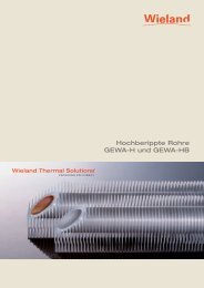
Quality Standard<br />
for ACR Copper Tubes<br />
in LWC
Foreword<br />
cuproclima ® is a protected<br />
tradename for high-quality<br />
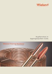
seamless copper tubes in levelwound<br />
coils (LWC) supplied to<br />
manufacturers of heat exchangers<br />
for the air conditioning and<br />
refrigeration (ACR) industry.<br />
This document describes the<br />
product requirements and delivery<br />
form of the tubes for such an end<br />
use. The specification has been<br />
established in view of the special<br />
manufacturing requirements of the<br />
ACR industry. As such it covers<br />
the main national and international<br />
standards.<br />
It should be pointed out that<br />
the cuproclima ® specification<br />
supports the new European<br />
Pressure Equipment Directive<br />
97/23/EC.<br />
Of course, the production sites<br />
of <strong>Wieland</strong>-Werke AG have<br />
been certified according to<br />
DIN EN ISO 9001 : 2000 for<br />
copper tubes. The quality system<br />
of <strong>Wieland</strong>-Werke AG has<br />
been approved by the auditing<br />
company Bureau Veritas.<br />
Edition Revision Date<br />
1 0 May 2002<br />
1 1 June 2003
1.1 Melting and casting of<br />
round billets<br />
Tube manufacturing starts with<br />
a round billet of about 360 kg.<br />
A round billet is a cut length of<br />
cylindrical casting.<br />
In the manufacture of billets, the<br />
melting and casting process can<br />
be either in heats or continuous.<br />
1.2 Hot extrusion of shells<br />
Shells are produced on an<br />
extrusion press by piercing and<br />
extruding the billets. For this<br />
purpose, the billets are preheated<br />
to about 900 °C. To prevent the<br />
oxidation of the inner and outer<br />
surfaces of the shell, a special<br />
technique is used.<br />
1.3 Cold working<br />
The final dimension of the tube is<br />
reached by drawing (bull blocks,<br />
spinner blocks) or combination of<br />
rolling (tube reducer) and drawing.<br />
1.4 Level winding and eddy<br />
current testing<br />
After drawing the tubes are level<br />
wound. The eddy current tester<br />
is linked to the level winder. Whilst<br />
the tube is being level wound,<br />
it is simultaneously 100 % eddy<br />
current tested.<br />
1.5 Annealing<br />
To achieve the final temper the<br />
tubes are annealed. The annealing<br />
is performed in a protective<br />
atmosphere (including other<br />
conditions) to eliminate oxidation<br />
and ensure a clean inside/outside<br />
surface.<br />
1.6 Packaging<br />
After the annealing, the tubes<br />
shall be packed in such a way that<br />
damage during transport and<br />
storage is avoided.<br />
1.7 Super clean quality<br />
On request, copper tubes are<br />
also available with particularly high<br />
inside cleanliness in the so-called<br />
super clean quality.<br />
1.8 Quality control<br />
The purpose of quality control<br />
during the manufacturing<br />
process is to identify at the<br />
earliest possible stage any<br />
defect deleterious to the final<br />
product and to stop such<br />
material from proceeding in the<br />
process. For that purpose, the<br />
product itself, the manufacturing<br />
parameters as well as the<br />
machinery, equipment and<br />
tooling at the different stages<br />
are submitted to permanent<br />
controls as specified in the QAM<br />
and the documented procedures.<br />
1<br />
1. Description of manufacturing process and quality controls within the manufacturing process
2. Product specification<br />
2<br />
2.1 Scope<br />
The purpose of this specification<br />
is to define the chemical,<br />
geometrical, mechanical and<br />
other characteristics of seamless<br />
round copper tubes used in the<br />
manufacture of heat exchangers<br />
for air conditioning and<br />
refrigeration equipment and the<br />
procedures used to test these<br />
characteristics.<br />
These tubes are supplied in<br />
LEVEL-WOUND COILS in an<br />
annealed temper and with<br />
appropriate packaging.<br />
2.2 General statement<br />
When tubes are ordered<br />
according to this cuproclima ®<br />
specification, the requirements<br />
listed in items 2.3 - 2.7 shall<br />
apply. This specification covers<br />
among others the following<br />
standards (latest editions):<br />
ASTM B 68 C 12200 (USA) light annealed<br />
B 743 (DHP) soft annealed<br />
EN 12735-2 Cu-DHP (Europe) Y040 light annealed<br />
Y035 soft annealed<br />
2.3 Definitions<br />
● Seamless tube: a tube<br />
produced with a continuous<br />
periphery at all stages of<br />
the production;<br />
● Coil: a length of tube wound<br />
into a series of connected turns<br />
(without cardboard reel);<br />
● Level-wound coil (LWC): a coil<br />
in which the tube is wound into<br />
layers parallel to the axis of the<br />
coils such that successive turns<br />
in a given layer are next to one<br />
another (without cardboard<br />
reel);<br />
● Cardboard reel: Type of<br />
packaging for LWC made of<br />
cardboard material. To use<br />
for customers without coil<br />
adapters in decoiling operation.<br />
● The term “unaided eye” as<br />
used in this specification means<br />
that the use of corrective<br />
spectacles to reach normal<br />
vision are permitted.<br />
● Local defects: a discontinuity<br />
localised in a very short length<br />
of the tube (holes, cracks,<br />
dents, inclusions, etc.)<br />
● Longitudinal defect: a non-local<br />
discontinuity which involves a<br />
certain length of the tube.<br />
2.4 Order specification<br />
Order specification shall include<br />
the following information:<br />
● Copper tubes according to<br />
cuproclima ® quality standard<br />
● Total quantity (kg) of each item<br />
● Material designation<br />
(deoxidized high residual<br />
phosphorus copper)<br />
● Temper (light or soft annealed)<br />
● Dimensions (outside diameter<br />
x wall thickness)<br />
● Maximum coil weight<br />
● Type of packing (without or with<br />
cardboard reel)<br />
● Special requirements<br />
(e.g. maximum cardboard<br />
reel or coil dimensions,<br />
sealing of the tube ends,<br />
mill test certificate, etc.)
2.5 Specification and<br />
requirements<br />
2.5.1 Material<br />
The tubes are made of<br />
phosphorus deoxidized copper.<br />
The chemical composition shall<br />
meet the requirements of table 2.<br />
2.5.2 Temper<br />
Tubes are normally supplied in<br />
“light annealed Y040” temper.<br />
They can also be supplied in<br />
“soft annealed Y035” temper.<br />
Respective mechanical properties<br />
and grain size shall meet the<br />
requirements of table 3.<br />
2.5.3 Dimensions and<br />
tolerances<br />
The tubes are defined by<br />
● the outside diameter (d)<br />
● the wall thickness (t)<br />
2.5.3.1 Recommended sizes<br />
<strong>Cuproclima</strong> recommends the sizes<br />
in table 4.<br />
Other sizes can be supplied upon<br />
agreement.<br />
2.5.4 Surface quality<br />
The inner and outer surfaces of<br />
the tubes shall be clean and<br />
smooth.<br />
The maximum permissible residue<br />
on the inner surface of the tube<br />
measured in specific cleanliness<br />
tests (ASTM B 743 or comparable)<br />
is 25 mg/m 2. On request, the<br />
ends of each coil shall be closed<br />
to prevent any contamination of<br />
the inner surface.<br />
2.5.5 Mechanical integrity<br />
2.5.5.1 Drift expanding<br />
No crack, break or tearing of<br />
the metal shall be visible to the<br />
unaided eye after a specific drift<br />
expanding test.<br />
The outside diameter of the tube<br />
shall be expanded by 40 %.<br />
2.5.5.2 Eddy current testing<br />
After the final draw, the tubes<br />
shall be 100 % tested in an eddy<br />
current testing unit. Signals<br />
indicating possible defects on<br />
the tube surface trigger a colour<br />
marking at the point concerned for<br />
subsequent removal by the end<br />
user. The marking shall not deform<br />
the tube (usually black marks).<br />
The permissible number of black<br />
marks shall comply with the<br />
values given in table 7. This<br />
number is proportional to the<br />
coil weight.<br />
2.5.6 Conditions of delivery<br />
2.5.6.1 Delivery form<br />
The tubes can be delivered either<br />
in bare coils or on cardboard reels.<br />
Common range of bare coils and<br />
cardboard reel sizes are given in<br />
table 8. Precise figures for weights<br />
and dimensions are obtainable<br />
from the manufacturer.<br />
2.5.6.2 Weight tolerance<br />
If the nominal weight of the coil<br />
is indicated in the order, no coil<br />
shall weigh less than 70 % of the<br />
nominal weight per shipment and<br />
a maximum of 20 % of the coils<br />
shall have this minimum weight.<br />
Example:<br />
Shipment of 10 LWC,<br />
nominal weight 150 kg:<br />
No coil shall weigh less than<br />
105 kg (70 % of the nominal<br />
weight) and a maximum of<br />
2 coils (20 % of the coils) shall<br />
weigh 105 kg.<br />
2.5.6.3 Packing and labeling<br />
For transportation the coils are<br />
stacked on pallets one above the<br />
other.<br />
They shall be packaged in such<br />
a way that they are protected<br />
from any damage under normal<br />
transportation, storing and<br />
handling conditions.<br />
Each coil shall be provided with<br />
a label giving at least the following<br />
information in a legible and<br />
permanent form:<br />
● tube dimensions<br />
● coil net weight<br />
● number of eddy current black<br />
marks<br />
● lot identification number<br />
3
4<br />
Each pallet shall be provided with<br />
a label with at least the following<br />
information:<br />
● manufacturer<br />
● customer<br />
● shipping address<br />
● order number<br />
● dimensions and temper<br />
● total gross and net weight<br />
2.6 Test procedure<br />
This item describes the testing of<br />
the final product.<br />
2.6.1 Number of tests<br />
The number of tests on final<br />
product is given in table 9.<br />
2.6.2 Retests<br />
Retests may be performed if only<br />
one specimen per property out of<br />
a batch of 15 tonnes maximum<br />
fails. In that case, four additional<br />
samples from different coils of<br />
the same batch shall be taken.<br />
The results on all these additional<br />
samples have to meet the<br />
requirements. Otherwise the<br />
entire batch shall be rejected.<br />
If the result of more than one<br />
specimen fails to meet the<br />
requirement for a specific property,<br />
the entire batch shall be rejected.<br />
2.6.3 Test methods<br />
2.6.3.1 Methods of analysis<br />
The chemical composition shall be<br />
determined by chemical or spectrographic<br />
methods according to<br />
ASTM E53, E62, E478 or ISO<br />
1553 and ISO 4741.<br />
2.6.3.2 Tensile test<br />
The tensile test shall be carried<br />
out according to EN 10002-1.<br />
2.6.3.3 Grain size definition<br />
The grain size shall be determined<br />
according to the ASTM standard<br />
E112 (comparison procedure or<br />
linear intercept procedure).<br />
For quality control during the<br />
manufacturing process other<br />
appropriate methods may be<br />
used.<br />
2.6.3.4. Cleanliness test<br />
To perform the cleanliness test<br />
according to ASTM B743 or<br />
EN 723, a section from the<br />
outside end of the coil, not less<br />
than 1.5 m long, is used.<br />
The inside of the tube is washed<br />
with a suitable solvent.<br />
The residue remaining after<br />
evaporation of the solvent<br />
shall be determined.<br />
For the routine quality control,<br />
other methods may be used.<br />
2.6.3.5 Drift expansion test<br />
This test shall be carried out<br />
according to ISO 8493, using a<br />
conical mandrel having a 60°<br />
included angle.<br />
2.6.3.6 Eddy current testing<br />
After the final draw, the tubes<br />
shall be passed through an eddy<br />
current testing unit adjusted<br />
to provide information on the<br />
suitability of the tube for the<br />
intended application. For this<br />
purpose, testing procedures<br />
shall detect both local and<br />
longitudinal defects.<br />
2.6.3.6.1 Local defects<br />
Testing shall follow the procedures<br />
of ASTM Practice E 243 Item<br />
7.1.2b or EN 1971, except for the<br />
determination of the “end effect”.<br />
The calibration tube used to adjust<br />
the sensitivity of the unit shall be<br />
selected from a typical production<br />
run and shall be representative of<br />
the purchase order.<br />
The artificial defects used when<br />
calibrating the unit shall be a set<br />
of three holes, each drilled<br />
radially through the tube wall<br />
in each of three successive<br />
transverse planes at 0 – 120 and –<br />
240 degrees (table 10, Fig. 2). The<br />
holes shall be spaced to provide<br />
signal resolution adequate for<br />
interpretation.<br />
Alternatively, a calibration tube<br />
with one hole may be used.<br />
In this case the calibration tube<br />
shall be passed through the<br />
eddy current testing unit three<br />
times at 0 – 120 and –240 degrees<br />
(see EN 1971 – item 5).<br />
The diameters of the drilled holes<br />
are given in table 10.<br />
As an alternative, the E. C. test<br />
and calibration of the equipment<br />
shall follow the procedure of<br />
DKI-Werkstoffblatt No. 781<br />
class A.
2.6.3.6.2 Longitudinal defects<br />
Longitudinal defects can be<br />
detected by summing up, in a<br />
specific tube length, a certain<br />
number of signals smaller than<br />
those defined in item 2.6.3.6.1.<br />
Calibration of the testing unit for<br />
this purpose shall be done in<br />
such a way that all defects that<br />
could be harmful to the end use,<br />
according to the manufacturer’s<br />
experience, shall be detected.<br />
Other appropriate methods with<br />
the same sensitivity may be used.<br />
2.6.3.7 Tolerances on outside<br />
diameter<br />
Tolerances on the outside<br />
diameter are given in table 5.<br />
The average outside diameter<br />
is defined as half of the sum of<br />
any two outside diameters<br />
normal to each other in the<br />
same cross-section.<br />
dmax + dmin daver = (mm)<br />
2<br />
The roundness tolerance refers<br />
to the deviation of the tube<br />
cross-section from the circular<br />
form.<br />
The percentage roundness is<br />
defined as follows:<br />
roundness<br />
tolerance<br />
dmax – dmin = x 100 %<br />
d aver<br />
where:<br />
d max = maximum diameter (mm)<br />
d min = minimum diameter (mm)<br />
d aver = average diameter (mm)<br />
2.6.3.8 Tolerances on wall<br />
thickness<br />
The wall thickness tolerances are<br />
given in table 6.<br />
The average wall thickness is<br />
defined as half of the sum of<br />
maximum and minimum wall thikkness<br />
at any cross-section<br />
of the tube.<br />
tmax + tmin taver = (mm)<br />
2<br />
Eccentricity (mm) is defined as<br />
follows:<br />
tmax – tmin eccentricity = (mm)<br />
2<br />
where:<br />
tmax = maximum wall thickness<br />
(mm)<br />
tmin = minimum wall thickness<br />
(mm)<br />
at any cross-section of the tube.<br />
Non-uniformity of wall thickness<br />
(%) refers to the deviation of the<br />
maximum and / or minimum<br />
wall thickness from the average<br />
wall thickness.<br />
tmax – tmin NUWT = x 100 (%)<br />
tmax + tmin Note:<br />
The dimensions are determined<br />
with commercial measuring<br />
equipment.<br />
2.7 Mill test certificate<br />
Upon request, a mill test<br />
certificate shall be supplied<br />
identifying the shipment and<br />
giving the test results of the<br />
final product according to<br />
this specification.<br />
5
Tables<br />
6<br />
Table 1<br />
Description of quality<br />
control within the<br />
manufacturing process<br />
Table 2<br />
Chemical analysis<br />
Table 3<br />
Mechanical properties<br />
and grain size<br />
Manufacturing Parameters to be controlled<br />
stage on product on equipment<br />
Melting and casting<br />
Hot extrusion<br />
Cold working<br />
Level winding including<br />
ec-testing<br />
Annealing<br />
● chemical composition<br />
● dimensions<br />
● quality of surface and<br />
of cut ends<br />
● dimensions incl.<br />
eccentricity<br />
● surface quality<br />
● dimensions<br />
● surface quality<br />
● dimensions<br />
● surface quality<br />
● quality of defect<br />
marking<br />
● number of defects<br />
● surface quality<br />
● inner surface:<br />
visually on a cross<br />
cut coil or/and by<br />
cleanliness test<br />
Packaging ● quality of packaging<br />
● melting and casting<br />
temperature<br />
● cooling parameters<br />
● casting speed<br />
● heating parameters<br />
● tool quality<br />
● tool dimensions and<br />
quality<br />
● lubrication<br />
● tool quality<br />
● adjustment and proper<br />
functioning of EC and<br />
marking devices<br />
● time<br />
● temperature<br />
● atmosphere<br />
Standard Material Cu (+ Ag) % P % Bi % Pb %<br />
designation min. max. max.<br />
cuproclima ® CU-DHP 99.90 0.015 – 0.040 0.001 0.003<br />
ASTM C 12200 99.90 0.015 – 0.040 – –<br />
EN 12735-2 CU-DHP min. 99.90 0.015 – 0.040 – –<br />
Temper proof *) Tensile Elongation Average<br />
stress, R p 0.2 strength R m A grain size<br />
N/mm 2 min. N/mm 2 min. % mm<br />
Light annealed Y040 40 – 90 220 45 0.015 – 0.035<br />
EN 12735-2 Y040 40 – 90 220 40 0.015 – 0.040<br />
Soft annealed **) Y035 35 – 80 210 48 0.030 – 0.060<br />
EN 12735-2 Y035 35 – 80 210 40 0.030 – 0.060<br />
**) R p 0.2 values are affected by test specimen preparation but shall always meet the<br />
above requirements.<br />
**) Only on special request, but wall thickness minimum 0.5 mm.
Table 4<br />
Recommended sizes<br />
Table 5<br />
Tolerances on<br />
outside diameter<br />
Wall<br />
inch .011 .012 .014 .016 .018 .020 .025 .028<br />
O.D. mm 0.28 0.30 0.35 0.40 0.45 0.50 0.63 0.70<br />
inch mm<br />
5/16 7.94 ● ● ● ●<br />
3/8 9.53 ● ● ● ● ● ●<br />
1/2 12.70 ● ● ● ● ●<br />
5/8 15.87 ● ● ● ● ●<br />
Nominal diameter range (mm)<br />
from 6.00 over 9.52 over 13.00 over 16.00 over 22.00<br />
to 9.52 to 13.00 to 16.00 to 22.00 to 28.00<br />
Average diameter ± 0.04 ± 0.05 ± 0.05 – t ≤ 0.40<br />
(mm) ± 0.04 ± 0.05 ± 0.08 t > 0.40<br />
Roundness 4.0 5.0 7.0 *) – t ≤ 0.40<br />
(%) 3.5 4.0 6.0 *) *) 0.40 < t ≤ 0.70<br />
3.0 3.5 5.0 *) *) 0.70 < t ≤ 1.00<br />
*) *) 1.00 < t ≤ 1.20<br />
*) *) 1.20 < t ≤ 1.50<br />
*) Upon agreement<br />
Table 6<br />
Tolerances on<br />
wall thickness<br />
Max. permissible deviation<br />
at any *) point (mm)<br />
*) *) 1.50 < t ≤ 2.00 Wall thickness range (mm)<br />
Nominal wall thickness range (mm)<br />
from 0.25 over 0.30 over 0.35 over 0.40 over 0.50 over 0.63 over 0.80 over 1.00 over 1.20 over 1.50 over 1.80<br />
to 0.30 to 0.35 to 0.40 to 0.50 to 0.63 to 0.80 to 1.00 to 1.20 to 1.50 to 1.80 to 2.00<br />
±0.025 ±0.030 ±0.030 ±0.040 ±0.050 ±0.060 ±0.070 ±0.080 ±0.090 ±0.100 ±0.110<br />
Tolerances on average ±0.01 ±0.015 ±0.020 ±0.025 ±0.030 ±0.035 ±0.05 ±0.05<br />
wall thickness<br />
(mm)<br />
*) Includes eccentricity<br />
Note: Nominal diameter x nominal wall thickness in table 6 are reference values and<br />
shall be defined upon agreement!<br />
from 6.00<br />
to 9.52<br />
over 9.52<br />
to 13.00<br />
over 13.00<br />
to 16.00<br />
over 16.00<br />
to 28.00<br />
Nominal outside<br />
diameter range (mm)<br />
7
8<br />
Table 7<br />
Permissible number of<br />
eddy current black marks<br />
per coil.<br />
The number is proportional<br />
to the coil weight,<br />
reference coil weight = 100 kg.<br />
The max. number of black marks<br />
per coil is calculated on the<br />
basis of the nominal coil weights<br />
(proportional to the reference coil<br />
weight of 100 kg). The maximum<br />
number of eddy current black<br />
marks remains constant within<br />
the permissible deviation from<br />
the nominal weight.<br />
Table 8<br />
Coil dimensions<br />
OD Wall Ø Max. number Max. number of<br />
- thickness Testhole of black black marks per<br />
marks per min. 5 t order<br />
100 kg coil<br />
Nominal coil weight<br />
mm mm mm 100 kg 150 kg 300 kg<br />
6.00 – 9.53 < 0.35 0.4 3 1.5 2.3 4.5<br />
6.00 – 9.53 ≥ 0.35 0.6 3 1.0 1.5 3.0<br />
9.54 – 20.00 all 0.6 3 0.8 1.2 2.4<br />
20.01– 28.00 all 0.7 3 0.8 1.2 2.4<br />
Usual nominal Permissible deviation from Max. number of black<br />
coil weights nominal weight per 1 coil marks per 1 coil<br />
kg kg WSFS<br />
100 70 – 110 3<br />
150 105 – 165 5<br />
300 210 – 330 9<br />
Weight Outside Inside Total Arbor hole<br />
diameter diameter width diameter<br />
OD ID W AD<br />
kg mm mm mm mm<br />
70 – 150 *) max. 1,130 600 + 10 160 – 320 130<br />
*) higher weights upon agreement<br />
Fig. 1
Table 9<br />
Number of tests<br />
on final product<br />
Table 10<br />
Calibration standard<br />
for ec-testing<br />
(diameter of drilled holes)<br />
Type of test<br />
Mandatory test Number of tests<br />
● Tensile one per lot *)<br />
● Grain size one per lot<br />
● Eddy current 100 %<br />
● Dimensions **) one per lot<br />
● Drift expansion one per lot<br />
● Cleanliness **) per lot<br />
Upon agreement<br />
● Analysis ***)<br />
● Hardness<br />
***) A lot is a quantity of 2500 kg of tubes in the same temper<br />
and dimensions.<br />
***) Constantly controlled during manufacturing process, see table 1.<br />
***) Analysis according to E 10204 2.2.<br />
Tube outside diameter Diameter of drilled holes<br />
mm mm<br />
from 6 to 9.53 0.4<br />
over 9.53 to 19.00 0.6<br />
over 19 to 22 0.7<br />
Fig. 2
WIELAND-WERKE-AG<br />
www.wieland.de<br />
89079 Ulm, Graf-Arco-Str. 36, Germany, Tel.: +49 (0)731 944-0, Fax: +49 (0)731 944-2820<br />
CUPROCLIMA ®<br />
Quality Standard<br />
of <strong>Wieland</strong>-Werke AG<br />
Tube Division<br />
0541-04 041/06.03Gs 0,5 leR (R+G)