LOW Finned Tubes GEWA-K GEWA-KS
GEWA-K - Wieland Thermal Solutions
GEWA-K - Wieland Thermal Solutions
- No tags were found...

You also want an ePaper? Increase the reach of your titles
YUMPU automatically turns print PDFs into web optimized ePapers that Google loves.
thermal solutions<br />
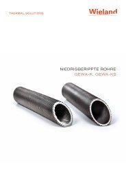
<strong>LOW</strong> <strong>Finned</strong> <strong>Tubes</strong><br />
<strong>GEWA</strong>-K, <strong>GEWA</strong>-<strong>KS</strong>
Low <strong>Finned</strong> <strong>Tubes</strong> <strong>GEWA</strong>-k, <strong>GEWA</strong>-<strong>KS</strong><br />
Wieland <strong>GEWA</strong>-K and <strong>GEWA</strong>-<strong>KS</strong> tubes are low finned tubes<br />
in copper and copper alloys as well as carbon steel, stainless<br />
steel and titanium. They are mainly used in the refrigeration and<br />
air-conditioning industry (refrigerant condenser and refrigerant<br />
evaporator), in machine and equipment industry (oil and gas<br />
cooler), in the process and power industry (cooler, preheater,<br />
condenser evaporator and reboiler).<br />
<strong>GEWA</strong>-K tubes have a plain inner surface. <strong>GEWA</strong>-<strong>KS</strong> tubes<br />
have grooves on the inner surface for optimum heat transfer.<br />
Interesting applications of copper and copper-alloy tubes<br />
include dry-expansion evaporators in the air-conditioning<br />
and refrigeration industry with tube-side evaporation of safety<br />
refrigerants such as R134a, R407C, R404A and shell-side cooling<br />
using water and water/glycol mixtures. Further applications<br />
are coaxial evaporators, compressed air driers and other heat<br />
exchangers (e.g. water/water, oil/water, etc.).<br />
<strong>GEWA</strong>-K and <strong>GEWA</strong>-<strong>KS</strong> tubes in carbon steel and stainless steel<br />
are used for various applications in the oil and gas, including<br />
refining, petrochemical, chemical and gas-processing as well<br />
as power industry. Cost-effective solutions such as compact<br />
design, reduction of the number of heat exchangers per unit and<br />
process efficiency improvement can be developed for various<br />
projects ranging from individual heat exchanger replacement and<br />
capacity expansion of existing plants to new plant construction.<br />
A version of the <strong>GEWA</strong>-K tube with a wide fin spacing of<br />
11.5 fpi and a fin thickness of 0.95 mm is suitable for very robust<br />
solutions, particularly for operating conditions involving corrosion<br />
and fouling, e.g. in the refining industry.<br />
The following three typical applications demonstrate the<br />
savingpotential offered by low-finned and especially dual<br />
enhanced finned tubes. This cost reduction is multiplied by<br />
savings made in the overall design (for example refrigerant and<br />
process fluid charges, piping, racks, support structures and<br />
foundations).<br />
2
Tube length<br />
5<br />
/8” Wieland <strong>GEWA</strong>-<strong>KS</strong> tube<br />
4.7 metres<br />
5<br />
/8” plain tube<br />
13.0 metres<br />
– 65 %<br />
Operating parameters<br />
TEMA type: AEL; capacity: 900 kW; refrigerant R404A T sat = –22 °C and CaCl 2 , 25 % brine;<br />
refrigerant (tube side): R404a; 400 tubes each; working fluid (shell side): CaCl 2 , 25 % brine<br />
Dry-expansion evaporator<br />
Size reduction of dry-expansion<br />
evaporator by 65 % through the use<br />
of <strong>GEWA</strong>-<strong>KS</strong> tubes<br />
Compared to plain tubes. the size of a dryexpansion<br />
evaporator can be reduced.<br />
at constant capacity, to about one third<br />
using Wieland <strong>GEWA</strong>-<strong>KS</strong> finned tubes at<br />
the operating conditions indicated.<br />
Total weight<br />
¾” Wieland <strong>GEWA</strong>-<strong>KS</strong> tube<br />
76 t<br />
¾” Wieland <strong>GEWA</strong>-K tube<br />
96 t<br />
¾” plain tube<br />
157 t<br />
– 51 %<br />
– 38 %<br />
Operating parameters<br />
Capacity: 61 MW; TEMA type: NXN, 1-pass; shell Ø = 2,280 mm; number of tubes: 6467;<br />
propane (shell side): T sat = 36 °C; cooling water (tube side): T inlet/outlet = 22.0/31.2 °C<br />
Propane-refrigerant<br />
condenser<br />
Weight reduction of propanerefrigerant<br />
condenser for LNG plant<br />
by 50 %<br />
In the construction of large heat-exchanger<br />
equipment the use of <strong>GEWA</strong>-K<br />
and <strong>GEWA</strong>-<strong>KS</strong> finned tubes, compared<br />
to plain tubes, makes it possible to meet<br />
the requirements regarding maximum<br />
unit size. This advantage is demonstrated<br />
for a typical large-scale project in the<br />
Persian Gulf where the total weight of the<br />
condenser could be halved.<br />
Tube type 1” plain tube, carbon steel 1” <strong>GEWA</strong>-<strong>KS</strong> tube carbon steel<br />
Heat exchanger / unit<br />
2 heat exchangers (1,300 mm 1 heat exchanger (1,500 mm shell<br />
shell Ø x 4.88 m tube length) Ø x 6.1 m tube length)<br />
Number of tubes [pieces] 1,292 1,782<br />
Tube length [m] 4.8 – 14 %<br />
6.1<br />
Shell-side pressure<br />
drop<br />
[kPa] 33.0 – 50 %<br />
16.5<br />
Tube-side pressure<br />
drop<br />
[kPa] 63 – 38 %<br />
24<br />
Heat transfer coefficient<br />
h<br />
[W/m 2 K] 243 + 87 %<br />
455<br />
Operating parameters<br />
Capacity: 2.0 MW;<br />
TEMA type: AES; crude oil (tube side): T inlet/outlet = 25 °C/29 °C;<br />
Kerosine (shell side): T inlet/outlet = 47.8 °C/29.0 °C<br />
Kerosene run-down<br />
cooler<br />
Reduction of number of heat<br />
exchangers by 50 %<br />
For preheating crude oil in a refinery, the<br />
number of heat exchangers could be<br />
reduced from two to one through the use<br />
of <strong>GEWA</strong>-<strong>KS</strong> tubes, compared to plain<br />
tubes, while at the same time achieving a<br />
pressure drop reduction by 50 %.<br />
3
Low <strong>Finned</strong> <strong>Tubes</strong> <strong>GEWA</strong>-k, <strong>GEWA</strong>-<strong>KS</strong><br />
Production and processing<br />
The fins are obtained by roll forming the outer surface of a plain<br />
tube. This process results in an increase in strength of the finned<br />
sections, whereas the plain ends and lands remain soft. Soft<br />
annealing of the tubes is required if they have to be suitable for<br />
bending and coiling.<br />
Advantages of <strong>GEWA</strong>-K and <strong>GEWA</strong>-<strong>KS</strong> tubes<br />
• Optimised inner to outer surface ratio<br />
• Compact designs through high specific heat capacity<br />
• Enhanced performance through inner structures (<strong>GEWA</strong>-<strong>KS</strong>)<br />
• Flexible design possible as bent or coiled heat exchangers<br />
<strong>Tubes</strong> in alloys susceptible to stress corrosion cracking such<br />
as CuZn28Sn1 or CuZn20Al2 are thermally stress relieved after<br />
finning. Heat treatment is also possible for finned tubes made<br />
from all other materials for recrystallisation (normalisation) of the<br />
structure, <strong>GEWA</strong>-K finned tubes resist very high mechanical and<br />
thermal stress. The fin diameter does not exceed the maximum<br />
outside diameter of the plain tube sections at any single point.<br />
Technical service<br />
Quality assurance<br />
To ensure consistent product quality, Wieland-Werke AG has a<br />
sophisticated quality control system according to DIN EN ISO<br />
9001 which has been verified and certified by the independent<br />
certification company, KIWA International Cert. Since 30<br />
December 2002, our test laboratories in the Central Laboratory<br />
and Development Services have been accredited to DIN EN<br />
ISO/IEC 17025 and DIN EN ISO 9001 as test and certification<br />
laboratories.<br />
Our Technical Marketing experts are available at any time as<br />
contact partners to work together with your experts from the<br />
very early product planning stages in order to obtain optimum<br />
results for the manufacturing stage and for your application.<br />
Wieland offers in-house thermal design software for shell-andtube<br />
dry-expansion evaporators with <strong>GEWA</strong>-<strong>KS</strong> finned tubes.<br />
For details please refer to www.wieland-thermalsolutions.com.<br />
In addition, tailor-made thermal designs are available from HTRI<br />
design software. In case of interest Wieland can provide heat<br />
transfer engineering service. Alternatively, for your own designs<br />
you may select the option “Wieland <strong>GEWA</strong>-<strong>KS</strong> tube” from the<br />
HTRI software.<br />
Tube dimensions and specifications<br />
The tube code system is described in the table tube identification.<br />
Weight conversion if not stated otherwise is based on K21<br />
Cu-DHP material. The weight of other copper alloys is weighted<br />
accordingly. In case of other materials such as carbon and<br />
stainless steel or titanium the reference weight is stated<br />
in the individual tables. All weights are approximate values.<br />
Actual values depend on the individual specification and the<br />
configuration of the tube with plain ends resp, plain lands.<br />
<strong>Finned</strong> tube ASTM standards are given by B359 for copper and<br />
copper alloys, A1012 for austenitic, ferritic and duplex alloys) as<br />
well as B891 for titanium.<br />
In case of stainless (austenitic, ferritic and duplex) and titanium<br />
tube materials tubes are available both in seamless and welded<br />
condition.<br />
Tube identification<br />
The overview of tube dimensions represents the current active<br />
portfolio. Modifications and other geometries are available upon<br />
request.<br />
K 26 15 12 080 00<br />
<strong>GEWA</strong>-K<br />
Number of fins<br />
per inch<br />
Fin height in<br />
1/10 mm<br />
Nominal root diameter<br />
in mm<br />
Root wall thickness in<br />
1/100 mm<br />
Code number for the inner structure<br />
(00 = plain inside surface)<br />
Weight conversion for copper alloys G = G K21 · f<br />
Length tolerances<br />
Material<br />
f<br />
l 1<br />
Length tolerance<br />
S28 0.96<br />
S76 0.93<br />
L10, L30 1.00<br />
< 2,000 +2 mm<br />
2,000–8,000 +1 ‰<br />
> 8,000 +0.7 ‰ (min. 8 mm)<br />
4
Materials and Properties<br />
Material designations Mechanical properties Physical properties<br />
Europe<br />
International<br />
Wieland<br />
EN Symbol Standard UNS / Grade Standard N/mm 2 N/mm 2 % HV kg/dm 3 10 -6 /K W/mK<br />
Copper and copper alloys<br />
Cu-DHP<br />
C12200<br />
K21 40 220 40 min. 40 8.94 17.7 >310<br />
CuZn28Sn1As C44300 S28 100 320 55 min. 60 8.56 20.0 110<br />
CuZn20Al2As EN12452 C68700 ASTM B359 S76 120 340 55 min. 60 8.35 19.0 100<br />
CuNi10Fe1Mn C70600 L10 90 290 30 min. 70 8.92 17.0 45<br />
CuNi30Mn1Fe C71500 L30 120 370 35 min. 85 8.93 16.0 30<br />
Carbon steel alloys<br />
P235GH EN10216-2 ASTM A179 235<br />
360–<br />
500<br />
25 72 HRB 7.85 13.0 57<br />
P255QL EN10216-4 Gr. 1, 6 ASTM A334 255<br />
360–<br />
490<br />
23 163 HB 7.85 13.0 57<br />
13CrMo4-5 EN10216-2 T11 ASTM A213 290<br />
430–<br />
580<br />
22 7.85 18.5 42<br />
X12CrMo5+I EN10216-2 T5 ASTM A213 175<br />
440–<br />
590<br />
20 89 HRB 7.80 19.0 28<br />
Austenitic stainless steel alloys<br />
1.4306<br />
TP304L<br />
180<br />
460–<br />
680<br />
40 90 HRB 7.90 17.0 15<br />
Yield strength, R p0.2<br />
(min.)<br />
1.4404 EN10216-5 TP316L 190<br />
ASTM A213<br />
DIN EN<br />
A249<br />
1.4541 10217-7 TP321 200<br />
1.4571 TP316Ti 190<br />
Tensile strength, R m<br />
(min.)<br />
490–<br />
690<br />
500–<br />
730<br />
490–<br />
690<br />
Elongation, A 5<br />
(min.)<br />
Hardness<br />
(max.)<br />
Density<br />
Thermal expansion<br />
coefficient<br />
Thermal conductivity<br />
40 90 HRB 7.98 17.5 15<br />
35 90 HRB 7.90 17.0 15<br />
35 90 HRB 8.00 18.0 15<br />
Ferritic and duplex stainless steel alloys<br />
1.4510 EN10296-2 TP439 ASTM A268 205 415 20 90 HRB 7.75 10.1 21<br />
1.4462<br />
EN10216-5<br />
EN10217-7<br />
S32205 ASTM A789 485 665 25 290 HBW 7.80 15.0 15<br />
1.4162<br />
EN10216-5<br />
EN10217-7<br />
S32101 ASTM A789 530 700 30 30 HRC 7.80 15.0 15<br />
Titanium<br />
3.7035 DIN17850 Gr. 2 ASTM B338<br />
275–<br />
450<br />
345 20 4.51 9.2 17<br />
5
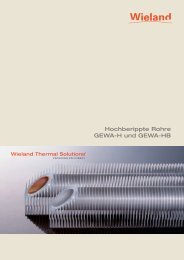
<strong>GEWA</strong>-K<br />
l 41 . l 42 ....l 4n<br />
d 1<br />
s 1<br />
l 2<br />
l 1<br />
l 3<br />
d 3 h 1<br />
s 2<br />
d 2<br />
d 4<br />
Symbols<br />
A a<br />
Outside surface<br />
A i<br />
Inside surface<br />
A a /A i Surface area ratio (outside to inside surface<br />
area within finned section)<br />
d 1<br />
Outside diameter of plain section<br />
d 2 Inside diameter of finned section (d 3 –2 x s 2 )<br />
d 3<br />
Root diameter<br />
d 4 Diameter over fins (≤ d 1 )<br />
h 1<br />
Fin height outside<br />
l 1<br />
Overall tube length<br />
l 2 <br />
Length of plain end<br />
l 3 Length of plain land<br />
l 4 <br />
Distance between land centre and tube end<br />
l 4 1 . l 42 . … l Distance between centre of lands and one<br />
4n<br />
and the same tube end<br />
m<br />
Fin pitch<br />
s 1<br />
Wall thickness of plain end and plain lands<br />
s 2<br />
Root wall thickness<br />
<strong>GEWA</strong>-K Fin pitch m = 2.20 mm Mean fin thickness R ≈ 0.95 mm<br />
11.5 fins/inch Fin height h = 1.50 mm Production length max. 18 m<br />
Tube No. Material Plain section <strong>Finned</strong> section Approx.<br />
weight<br />
A179 A334 A213<br />
T11 / T5<br />
(inch)<br />
d 1<br />
(mm)<br />
s1<br />
(mm)<br />
d 3<br />
(mm)<br />
s 2<br />
(mm)<br />
A a<br />
(m 2 /m)<br />
K-1115.12150-00 • • • 5⁄8 15.88 2.11 12.70 1.50 0.091 3.00 0.653<br />
K-1115.15150-00 • • • 3⁄4 19.05 2.11 15.90 1.50 0.111 2.74 0.825<br />
K-1115.22220-00 • • • 1 25.40 2.77 22.20 2.20 0.152 2.72 1.480<br />
K-1115.22245-00 • • • 1 25.40 3.05 22.20 2.45 0.152 2.80 1.590<br />
A a /A i<br />
(-)<br />
G CS<br />
(kg/m)<br />
<strong>GEWA</strong>-K Fin pitch m = 1.35 mm Mean fin thickness R ≈ 0.30 mm<br />
19 fins/inch Fin height h = 1.50 mm Production length max. 18 m<br />
Tube No. Material Plain section <strong>Finned</strong> section Approx.<br />
weight<br />
K21 L10 L30 S28 S76<br />
(inch)<br />
d 1<br />
(mm)<br />
s1<br />
(mm)<br />
d 3<br />
(mm)<br />
s 2<br />
(mm)<br />
A a<br />
(m 2 /m)<br />
K-1915.09080-00 • • 1⁄2 12.70 1.20 9.50 0.80 0.103 4.15 0.407<br />
K-1915.09090-00 • • 1⁄2 12.70 1.30 9.50 0.90 0.103 4.26 0.429<br />
K-1915.09100-00 • • • • • 1⁄2 12.70 1.40 9.50 1.00 0.103 4.37 0.450<br />
K-1915.09125-00 • • • • • 1⁄2 12.70 1.65 9.50 1.25 0.103 4.68 0.501<br />
K-1915.09150-00 • • • • • 1⁄2 12.70 1.90 9.50 1.50 0.103 5.04 0.549<br />
K-1915.12070-00 • 5⁄8 15.88 1.10 12.70 0.70 0.131 3.69 0.417<br />
K-1915.12080-00 • • 5⁄8 15.88 1.20 12.70 0.80 0.131 3.76 0.448<br />
K-1915.12090-00 • • 5⁄8 15.88 1.30 12.70 0.90 0.131 3.83 0.479<br />
K-1915.12100-00 • • • • • 5⁄8 15.88 1.40 12.70 1.00 0.131 3.90 0.510<br />
K-1915.12110-00 • • • • • 5⁄8 15.88 1.50 12.70 1.10 0.131 3.97 0.539<br />
K-1915.12120-00 • • • • • 5⁄8 15.88 1.60 12.70 1.20 0.126 3.89 0.561<br />
K-1915.12170-00 • • • • • 5⁄8 15.88 2.10 12.70 1.70 0.126 4.31 0.699<br />
A a /A i<br />
(-)<br />
G K21<br />
(kg/m)<br />
6
<strong>GEWA</strong>-K<br />
<strong>GEWA</strong>-K Fin pitch m = 1.35 mm Mean fin thickness R ≈ 0.30 mm<br />
19 fins/inch Fin height h = 1.50 mm Production length max. 18 m<br />
Tube No. Material Plain section <strong>Finned</strong> section Approx.<br />
weight<br />
K21 L10 L30 S28 S76<br />
d 1<br />
s1<br />
(mm)<br />
d 3<br />
(mm)<br />
s 2<br />
(mm)<br />
A a<br />
(m 2 /m)<br />
K-1915.15070-00 • 3⁄4 19.05 1.20 15.80 0.70 0.153 3.38 0.554<br />
K-1915.15080-00 • 3⁄4 19.05 1.30 15.80 0.80 0.153 3.43 0.594<br />
K-1915.15090-00 • • 3⁄4 19.05 1.35 15.80 0.90 0.153 3.48 0.633<br />
K-1915.15100-00 • • • • • 3⁄4 19.05 1.45 15.80 1.00 0.153 3.53 0.673<br />
K-1915.15125-00 • • • • • 3⁄4 19.05 1.75 15.80 1.25 0.153 3.66 0.768<br />
K-1915.15140-00 • • • • • 3⁄4 19.05 1.90 15.80 1.40 0.153 3.75 0.823<br />
K-1915.15150-00 • • • • • 3⁄4 19.05 2.00 15.80 1.50 0.154 3.83 0.814<br />
K-1915.15235-00 • • • • • 3⁄4 19.05 2.85 15.80 2.35 0.154 4.42 1.099<br />
K-1915.19100-00 • • 7⁄8 22.22 1.50 19.00 1.00 0.182 3.41 0.810<br />
K-1915.19125-00 • • • • • 7⁄8 22.22 1.75 19.00 1.25 0.182 3.51 0.927<br />
K-1915.19150-00 • • • • • 7⁄8 22.22 2.00 19.00 1.50 0.182 3.62 1.042<br />
K-1915.19170-00 • • • • • 7⁄8 22.22 2.20 19.00 1.70 0.182 3.71 1.130<br />
K-1915.19180-00 • • • • • 7⁄8 22.22 2.30 19.00 1.80 0.183 3.78 1.120<br />
K-1915.19250-00 • • • • • 7⁄8 22.22 3.00 19.00 2.50 0.183 4.16 1.409<br />
K-1915.22125-00 • • 1 25.40 1.75 22.20 1.25 0.211 3.41 1.087<br />
K-1915.22165-00 • • • • • 1 25.40 2.15 22.20 1.65 0.211 3.55 1.304<br />
K-1915.22210-00 • • • • • 1 25.40 2.60 22.20 2.10 0.212 3.75 1.476<br />
K-1915.22250-00 • • • • • 1 25.40 3.00 22.20 2.50 0.212 3.92 1.673<br />
(inch)<br />
(mm)<br />
A a /A i<br />
(-)<br />
G K21<br />
(kg/m)<br />
<strong>GEWA</strong>-K Fin pitch m = 1.35 mm Mean fin thickness R ≈ 0.30 mm<br />
19 fins/inch Fin height h = 1.42 mm Production length max. 18 m<br />
Tube No. Material Plain section <strong>Finned</strong> section Approx.<br />
weight<br />
A179<br />
A334<br />
(inch)<br />
d 1<br />
(mm)<br />
s1<br />
(mm)<br />
d 3<br />
(mm)<br />
s 2<br />
(mm)<br />
A a (m 2 /m)<br />
K-1914.12125-00 • • 5⁄8 15.88 1.65 12.90 1.25 0.121 3.70 0.507<br />
K-1914.12165-00 • • 5⁄8 15.88 2.10 12.90 1.65 0.121 4.01 0.594<br />
K-1914.16125-00 • • 3⁄4 19.05 1.75 16.00 1.25 0.148 3.49 0.635<br />
K-1914.16138-00 3⁄4 19.05 1.80 16.00 1.38 0.148 3.53 0.690<br />
K-1914.16165-00 • • 3⁄4 19.05 2.10 16.00 1.65 0.148 3.71 0.764<br />
K-1914.16210-00 • • 3⁄4 19.05 2.50 16.00 2.10 0.148 3.99 0.900<br />
K-1914.16235-00 • • 3⁄4 19.05 2.75 16.00 2.35 0.148 4.21 0.985<br />
K-1914.19165-00 • • 7⁄8 22.22 2.10 19.20 1.65 0.175 3.50 0.927<br />
K-1914.19210-00 • • 7⁄8 22.22 2.50 19.20 2.10 0.175 3.71 1.099<br />
K-1914.19240-00 • • 7⁄8 22.22 2.80 19.20 2.40 0.175 3.87 1.208<br />
K-1914.22210-00 • • 1 25.40 2.50 22.40 2.10 0.203 3.55 1.298<br />
K-1914.22240-00 • • 1 25.40 2.80 22.40 2.40 0.203 3.67 1.430<br />
K-1914.22275-00 • • 1 25.40 3.15 22.40 2.75 0.203 3.82 1.579<br />
A a /A i<br />
(-)<br />
G CS<br />
(kg/m)<br />
7
<strong>GEWA</strong>-K<br />
<strong>GEWA</strong>-K Fin pitch m = 1.00 mm Mean fin thickness R ≈ 0.30 mm<br />
26 fins/inch Fin height h = 1.50 mm Production length max. 18 m<br />
Tube No. Material Plain section <strong>Finned</strong> section Approx.<br />
weight<br />
K21 L10 L30 S28 S76 d 1 s1<br />
(inch) (mm) (mm)<br />
d 3<br />
(mm)<br />
s 2<br />
(mm)<br />
A a<br />
(m 2 /m)<br />
K-2615.09080-00 • • 1⁄2 12.70 1.20 9.50 0.80 0.129 5.20 0.329<br />
K-2615.09090-00 • • 1⁄2 12.70 1.30 9.50 0.90 0.129 5.33 0.351<br />
K-2615.09100-00 • • • • • 1⁄2 12.70 1.40 9.50 1.00 0.129 5.47 0.372<br />
K-2615.09125-00 • • • • • 1⁄2 12.70 1.65 9.50 1.25 0.129 5.87 0.423<br />
K-2615.09150-00 • • • • • 1⁄2 12.70 1.90 9.50 1.50 0.129 6.32 0.471<br />
K-2615.12070-00 • 5⁄8 15.88 1.10 12.70 0.70 0.167 4.70 0.408<br />
K-2615.12080-00 • • 5⁄8 15.88 1.20 12.70 0.80 0.167 4.79 0.440<br />
K-2615.12090-00 • • 5⁄8 15.88 1.30 12.70 0.90 0.167 4.88 0.471<br />
K-2615.12100-00 • • • • • 5⁄8 15.88 1.40 12.70 1.00 0.167 4.97 0.501<br />
K-2615.12110-00 • • • • • 5⁄8 15.88 1.50 12.70 1.10 0.167 5.06 0.531<br />
K-2615.12120-00 • • • • • 5⁄8 15.88 1.60 12.70 1.20 0.163 5.04 0.582<br />
K-2615.12170-00 • • • • • 5⁄8 15.88 2.10 12.70 1.70 0.163 5.58 0.720<br />
K-2615.15070-00 • 3⁄4 19.05 1.20 15.80 0.70 0.204 4.51 0.507<br />
K-2615.15080-00 • 3⁄4 19.05 1.35 15.80 0.80 0.204 4.57 0.547<br />
K-2615.15090-00 • • 3⁄4 19.05 1.45 15.80 0.90 0.204 4.64 0.587<br />
K-2615.15100-00 • • • 3⁄4 19.05 1.50 15.80 1.00 0.204 4.71 0.626<br />
K-2615.15150-00 • • • • • 3⁄4 19.05 2.00 15.80 1.50 0.199 4.95 0.839<br />
K-2615.15235-00 • • • • • 3⁄4 19.05 2.85 15.80 2.35 0.199 5.71 1.125<br />
K-2615.19100-00 • • 7⁄8 22.22 1.50 19.00 1.00 0.242 4.53 0.755<br />
K-2615.19125-00 • • • • 7⁄8 22.22 1.75 19.00 1.25 0.242 4.67 0.872<br />
K-2615.19165-00 • • • • • 7⁄8 22.22 2.15 19.00 1.65 0.242 4.91 1.003<br />
K-2615.19180-00 • • • • • 7⁄8 22.22 2.30 19.00 1.80 0.236 4.88 1.150<br />
K-2615.19250-00 • • • • • 7⁄8 22.22 3.00 19.00 2.50 0.236 5.37 1.439<br />
K-2615.22125-00 • • 1 25.40 1.75 22.20 1.25 0.281 4.54 1.023<br />
K-2615.22165-00 • • • • • 1 25.40 2.15 22.20 1.65 0.281 4.73 1.240<br />
K-2615.22210-00 • • • • • 1 25.40 2.60 22.20 2.10 0.274 4.85 1.510<br />
K-2615.22250-00 • • • • • 1 25.40 3.00 22.20 2.50 0.274 5.07 1.708<br />
A a /A i<br />
(-)<br />
G K21<br />
(kg/m)<br />
<strong>GEWA</strong>-K Fin pitch = 0.91 mm Mean fin thickness R ≈ 0.30 mm<br />
28 fins/inch Fin height h = 1.245 mm Production length max. 18 m<br />
Tube No. Material Plain section <strong>Finned</strong> section Approx.<br />
weight<br />
TP 439<br />
(inch)<br />
d 1<br />
s 1 (mm) d 3 (mm) s 2 (mm) A a (m 2 /m)<br />
(mm)<br />
A a /A l<br />
(-)<br />
G<br />
(kg/m)<br />
K-2813.16125-00 • 3/4 19.05 1.83 16.51 1.25 0.186 4.23 0.636<br />
K-2813.19125-00 • 7/8 22.22 1.83 19.68 1.25 0.218 4.04 0.763<br />
K-2813.22125-00 • 1 25.40 1.83 22.86 1.25 0.252 3.94 0.891<br />
8
<strong>GEWA</strong>-K<br />
<strong>GEWA</strong>-K Fin pitch m = 1.00 mm Mean fin thickness R ≈ 0.30 mm<br />
26 fins/inch Fin height h = 1.42 mm Production length max. 18 m<br />
Tube No. Material Plain section <strong>Finned</strong> section Approx.<br />
weight<br />
A179 A334 d 1 s 1<br />
(inch) (mm) (mm)<br />
d 3<br />
(mm)<br />
s 2<br />
(mm)<br />
A a<br />
(m 2 /m)<br />
K-2614.09100-00 1⁄2 12.70 1.40 9.70 1.00 0.118 4.80 0.343<br />
K-2614.12125-00 • • 5⁄8 15.88 1.65 12.90 1.25 0.155 4.74 0.525<br />
K-2614.12165-00 • • 5⁄8 15.88 2.10 12.90 1.65 0.155 5.09 0.612<br />
K-2614.16125-00 3⁄4 19.05 1.75 16.00 1.25 0.195 4.60 0.632<br />
K-2614.16165-00 • • 3⁄4 19.05 2.10 16.00 1.65 0.190 4.76 0.786<br />
K-2614.16210-00 • • 3⁄4 19.05 2.50 16.00 2.10 0.190 5.13 0.922<br />
K-2614.19125-00 • • 7⁄8 22.22 1.85 19.20 1.25 0.231 4.40 0.763<br />
K-2614.19200-00 • • 7⁄8 22.22 2.40 19.20 2.00 0.225 4.71 1.087<br />
K-2614.19240-00 • • 7⁄8 22.22 2.80 19.20 2.40 0.225 4.97 1.233<br />
K-2614.22165-00 • • 1 25.40 2.10 22.40 1.65 0.267 4.45 1.087<br />
K-2614.22210-00 • • 1 25.40 2.50 22.40 2.10 0.260 4.55 1.327<br />
K-2614.22240-00 • • 1 25.40 2.80 22.40 2.40 0.260 4.70 1.460<br />
A a /A i<br />
(-)<br />
G CS<br />
(kg/m)<br />
<strong>GEWA</strong>-K Fin pitch = 0.91 mm Mean fin thickness R ≈ 0.30 mm<br />
28 fins/inch Fin height h = 0.90 mm Production length max. 18 m<br />
Tube No. Material Plain section <strong>Finned</strong> section Approx.<br />
weight<br />
Lean-Duplex<br />
2101<br />
Duplex 2205<br />
(inch)<br />
d 1<br />
s 1 (mm) d 3 (mm) s 2 (mm) A a (m 2 /m)<br />
(mm)<br />
A a /A l<br />
(-)<br />
G<br />
(kg/m)<br />
K-2809.17107-00 • • 3/4 19.05 1.65 17.25 1.07 0.148 3.12 0.566<br />
K-2809.17125-00 • • 3/4 19.05 1.83 17.25 1.25 0.148 3.19 0.633<br />
K-2809.17165-00 • • 3/4 19.05 2.11 17.25 1.65 0.148 3.38 0.774<br />
K-2809.20107-00 • • 7/8 22.22 1.65 20.43 1.07 0.174 3.03 0.675<br />
K-2809.20125-00 • • 7/8 22.22 1.83 20.43 1.25 0.174 3.09 0.755<br />
K-2809.20165-00 • • 7/8 22.22 2.11 20.43 1.65 0.174 3.23 0.927<br />
K-2809.23107-00 • • 1 25.40 1.65 23.60 1.07 0.198 2.94 0.783<br />
K-2809.23125-00 • • 1 25.40 1.83 23.60 1.25 0.198 2.99 0.877<br />
K-2809.23165-00 • • 1 25.40 2.11 23.60 1.65 0.198 3.10 1.080<br />
K-2809.23183-00 • • 1 25.40 2.41 23.60 1.83 0.198 3.16 1.168<br />
9
<strong>GEWA</strong>-K<br />
<strong>GEWA</strong>-K Fin pitch = 0.85 mm Mean fin thickness R ≈ 0.30 mm<br />
30 fins/inch Fin height h = 0.90 mm Production length max. 18 m<br />
Tube No. Material Plain section <strong>Finned</strong> section Approx.<br />
weight<br />
A179<br />
A334<br />
TP 304<br />
L<br />
TP 316 L TP 316 Ti Ti Gr. 2<br />
d 1 s 1<br />
(inch) (mm)<br />
(mm)<br />
d 3<br />
(mm)<br />
s 2<br />
(mm)<br />
A a<br />
(m 2 /m)<br />
A a /A l<br />
(-)<br />
G CS<br />
(kg/m)<br />
K-3009.10125-00 • • • 1/2 12.70 1.65 10.90 1.25 0.100 3.79 0.523<br />
K-3009.14107-00 • • • • • 5/8 15.88 1.65 14.08 1.07 0.127 3.39 0.523<br />
K-3009.14125-00 • • • • • 5/8 15.88 1.83 14.08 1.25 0.127 3.49 0.580<br />
K-3009.14165-00 • • • • • 5/8 15.88 2.11 14.08 1.65 0.127 3.75 0.634<br />
K-3009.17107-00 • • • 3/4 19.05 1.65 17.25 1.07 0.152 3.20 0.648<br />
K-3009.17125-00 • • • 3/4 19.05 1.83 17.25 1.25 0.152 3.28 0.720<br />
K-3009.17165-00 • • • • • 3/4 19.05 2.11 17.25 1.65 0.152 3.47 0.799<br />
K-3009.17183-00 • • • • • 3/4 19.05 2.41 17.25 1.83 0.152 3.56 0.909<br />
K-3009.20125-00 • • • 7/8 22.22 1.83 20.42 1.25 0.181 3.22 0.860<br />
K-3009.20165-00 • • • 7/8 22.22 2.11 20.42 1.65 0.181 3.37 0.946<br />
K-3009.20183-00 • • • 7/8 22.22 2.41 20.42 1.83 0.181 3.44 1.090<br />
K-3009.23125-00 • • • 1 25.40 1.83 23.60 1.25 0.208 3.14 1.002<br />
K-3009.23165-00 • • • 1 25.40 2.11 23.60 1.65 0.208 3.26 1.104<br />
K-3009.23183-00 • • • • • 1 25.40 2.41 23.60 1.83 0.208 3.32 1.277<br />
K-3009.23211-00 • • • • • 1 25.40 2.77 23.60 2.11 0.208 3.42 1.468<br />
<strong>GEWA</strong>-K Fin pitch = 0.850 mm Mean fin thickness R ≈ 0.30 mm<br />
30 fins/inch Fin height h = 0.813 mm Production length max. 18 m<br />
K-3008.17071-00 • 3/4 19.05 1.25 17.42 0.71 0.144 2.86 0.297<br />
K-3008.23107-00 • 1 25.40 1.65 23.77 1.07 0.194 2.85 0.540<br />
<strong>GEWA</strong>-K Fin pitch m = 0.705 mm Mean fin thickness R ≈ 0.30 mm<br />
36 fins/inch Fin height h = 0.66 mm Production length max. 18 m<br />
Tube No. Material Plain section <strong>Finned</strong> section Approx.<br />
weight<br />
Ti Gr. 2<br />
(inch)<br />
d 1 s 1<br />
(mm) (mm)<br />
d 3<br />
(mm)<br />
s 2<br />
(mm)<br />
A a<br />
(m 2 /m)<br />
K-3607.17071-00 • 3⁄4 19.05 1.25 17.73 0.71 0.145 2.83 0.288<br />
K-3607.24071-00 • 1 25.40 1.25 24.08 0.71 0.195 2.74 0.376<br />
K-3607.24090-00 • 1 25.40 1.47 24.08 0.90 0.195 2.79 0.468<br />
K-3607.24107-00 • 1 25.40 1.65 24.08 1.07 0.195 2.83 0.515<br />
A a /A i<br />
(-)<br />
G<br />
(kg/m)<br />
<strong>GEWA</strong>-K Fin pitch m = 0.64 mm Mean fin thickness R ≈ 0.30 mm<br />
40 fins/inch Fin height h = 0.90 mm Production length max. 15 m<br />
Tube No. Material Plain section <strong>Finned</strong> section Approx.<br />
weight<br />
K21 L10 d 1 s 1<br />
(inch) (mm) (mm)<br />
d 3<br />
(mm)<br />
s 2<br />
(mm)<br />
A a<br />
(m 2 /m)<br />
K-4009.17070-00 • • 3⁄4 19.00 1.12 17.00 0.70 0.194 3.96 0.495<br />
K-4009.17090-00 • • 3⁄4 19.00 1.35 17.00 0.90 0.194 4.06 0.600<br />
A a /A i<br />
(-)<br />
G<br />
(kg/m)<br />
10
h 2<br />
s 2<br />
<strong>GEWA</strong>-<strong>KS</strong><br />
d 1<br />
s 1<br />
l 2<br />
l 4<br />
l 41 . l 42 .... l 4n<br />
d 4<br />
d 3 h 1<br />
d 2<br />
l 1<br />
l 3<br />
m<br />
Nomenclature<br />
A a<br />
Outside surface<br />
A i<br />
Inside surface<br />
A a /A i Surface area ratio (outside to inside surface<br />
area within finned section)<br />
d 1<br />
Outside diameter of plain section<br />
d 2 Inside diameter of finned section (d 3 –2 x s 2 )<br />
d 3<br />
Root diameter<br />
d 4 Diameter over fins (≤ d1)<br />
h 1<br />
Fin height outside<br />
h 2<br />
Fin height inside<br />
l 1<br />
Overall tube length<br />
l 2 <br />
Length of plain end<br />
l 3 Length of plain land<br />
l 4 <br />
Distance between land centre and tube end<br />
l 4 1 , l 42 , … l Distance between centre of lands and one<br />
4n<br />
and the same tube end<br />
m<br />
Fin pitch<br />
s 1<br />
Wall thickness of plain end and plain lands<br />
s 2<br />
Root wall thickness<br />
<strong>GEWA</strong>-<strong>KS</strong><br />
Production length K21 max. 8 m. steel max. 18 m<br />
Tube No. Material Plain section <strong>Finned</strong> section Approx.<br />
weight<br />
K21 A179 /<br />
A334<br />
TP 304L /<br />
TP316L /<br />
TP316Ti<br />
d 1<br />
(inch) (mm)<br />
s1<br />
(mm)<br />
h 1<br />
(mm)<br />
d 3<br />
(mm)<br />
s 2<br />
(mm)<br />
h 2<br />
(mm)<br />
A a<br />
(m 2 /m)<br />
A a /A i<br />
(–)<br />
G<br />
(kg/m)<br />
19 fpi<br />
K-1908.14070-22 • 5⁄8 15.88 1.30 0.80 14.1 0.70 0.45 0.091 1.36 0.460<br />
K-1908.17070-24 • 3⁄4 19.05 1.35 0.80 17.2 0.70 0.50 0.107 1.28 0.570<br />
K-1914.16140-53 • 3⁄4 19.05 2.11 1.40 16.1 1.40 0.20 0.149 2.91 0.785<br />
K-1915.22240-53 • 1 25.40 3.05 1.50 22.2 2.40 0.35 0.212 2.73 1.470<br />
30 fpi<br />
K-3009.14080-59 • 5/8 15.88 1.47 0.90 14.08 0.80 0.35 0.127 3.24 0.436<br />
K-3009.14100-59 • 5/8 15.88 1.65 0.90 14.08 1.00 0.35 0.127 3.35 0.497<br />
K-3009.14120-59 • 5/8 15.88 1.83 0.90 14.08 1.20 0.35 0.127 3.46 0.556<br />
K-3009.17140-48 • 3⁄4 19.05 2.11 0.90 17.1 1.40 0.40 0.162 2.81 0.780<br />
K-3009.17080-59 • 3/4 19.05 1.47 0.90 17.25 0.90 0.35 0.154 3.17 0.525<br />
K-3009.17107-59 • 3/4 19.05 1.65 0.90 17.25 1.07 0.35 0.154 3.24 0.602<br />
K-3009.17125-59 • 3/4 19.05 1.83 0.90 17.25 1.25 0.35 0.154 3.32 0.658<br />
K-3009.23220-48 • 1 25.40 2.80 0.90 23.4 2.20 0.40 0.212 2.71 1.450<br />
11
n<br />
Innovative Spirit.<br />
outstanding results.<br />
www.wieland-thermalsolutions.com<br />
This printed matter is not subject to revision. No claims can be derived from it unless there is evidence of intent or gross negligence. The product characteristics are not guaranteed and do not replace our experts' advice.<br />
0541-04 061/02.12 St 1 ODH (GWW/Al)