Technical information Diaphragm anti siphon valve ... - Oventrop
Technical information Diaphragm anti siphon valve ... - Oventrop
Technical information Diaphragm anti siphon valve ... - Oventrop

Create successful ePaper yourself
Turn your PDF publications into a flip-book with our unique Google optimized e-Paper software.
The <strong>Oventrop</strong> Quality Management<br />
System is certified to DIN-EN-ISO 9001<br />
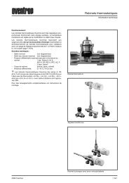
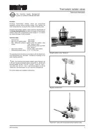
Tender specification:<br />
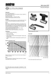
The <strong>Oventrop</strong> diaphragm <strong>anti</strong> <strong>siphon</strong> <strong>valve</strong> ”Oilstop V” is<br />
used in heating oil installations according to DIN 4755<br />
standard in which the maximum tank filling point is located at<br />
a higher level than the lowest point of the suction pipe.<br />
Should a leakage occur in the suction pipe between the <strong>anti</strong><br />
<strong>siphon</strong> <strong>valve</strong> and the burner, the <strong>valve</strong> will prevent the oil in<br />
the tank being <strong>siphon</strong>ed off. Installation is possible in the<br />
suction pipe of one pipe systems (with and without return<br />
flow feed) and two pipe systems.<br />
Item no. 210 42 03<br />
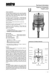
Function:<br />
When the burner is not in operation, a spring assisted piston<br />
shuts off the suction pipe between the tank and the succeeding<br />
system. Once the pump is switched on, the underlying<br />
pressure actuates the diaphragm, which via a tappet, will lift<br />
the piston and open the <strong>valve</strong>. During the operating time of<br />
the burner, the <strong>valve</strong> remains open.<br />
If a leakage occurs in the suction pipe, the underlying<br />
pressure disappears. Then the diaphragm releases the piston<br />
and the <strong>valve</strong> is closed.<br />
When the <strong>valve</strong> is set to ”entlüften” (deaerating), the piston<br />
is lifted off its seat and the safety function is deactivated.<br />
This facility enables a simple deaeration of the pipework<br />
when the system is put into operation for the first time or<br />
after maintenance/service works (e.g. filter change).<br />
Important: The required safety height for the system must be<br />
set after deaeration!<br />
When the <strong>valve</strong> is set to ”absperren” (isolation), the<br />
diaphragm is disabled. The <strong>valve</strong> may not be opened by<br />
system pressure. This facility enables maintenance/service<br />
works on parts of the pipe before or behind the <strong>valve</strong>.<br />
Attention: If the burner is switched on when the <strong>valve</strong> is<br />
isolated, the pump may be damaged!<br />
Advantages:<br />
– infinite adjustment ensuring low pressure loss<br />
– deaeartion function allowing a trouble-free setting into<br />
operation<br />
– isolation facility to carry out maintenance/service works<br />
and to isolate the system<br />
– leakage test of the system up to 6 bar with the <strong>valve</strong> being<br />
installed<br />
– <strong>valve</strong> can be lead sealed<br />
– compact construction<br />
– existing installations can be upgraded<br />
– functions without auxiliary energy<br />
– diaphragm and <strong>valve</strong> insert are fitted in such a way as to<br />
prevent tampering<br />
– maintenance-free <strong>valve</strong><br />
– pressure compensation in case of increase of oil<br />
temperature between <strong>valve</strong> and burner<br />
Installation and putting into operation:<br />
The difference in height ∆hv between the diaphram <strong>anti</strong><br />
<strong>siphon</strong> <strong>valve</strong> and the lowest point of the suction pipe may<br />
not exceed 4 m (max. adjustable safety height)!<br />
The <strong>valve</strong> is installed in the flow direction (arrow) of the<br />
suction pipe and must be situated above the maximum tank<br />
oil level. The <strong>valve</strong> may be installed in any position, but it is<br />
preferable to install it horizontally with the setting scale<br />
pointing downwards.<br />
The <strong>valve</strong> should be installed free from tension in a dry and<br />
easily accessible location. Care must be taken that no<br />
impurities (e.g. metal shavings) enter the <strong>valve</strong> body. The<br />
bore hole in the bonnet may not be polluted or covered.<br />
During operation, the <strong>valve</strong> must be protected (e.g. by an<br />
insert or a strainer) against heavy pollution.<br />
Non-return check <strong>valve</strong>s (without pressure balance) may<br />
impair the operation of the solenoid <strong>valve</strong>. In case of a possible<br />
pressure built-up caused by a rise in temperature, especially<br />
in separate oil storage rooms, they should be removed and<br />
inactivated.<br />
Before putting the system into operation, the <strong>valve</strong> must be<br />
set to ”entlüften” (deaerating) by turning the handwheel<br />
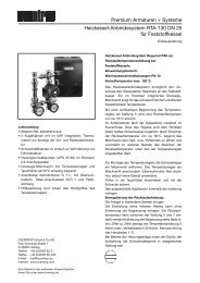
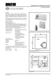
<strong>Technical</strong> <strong>information</strong><br />
<strong>Diaphragm</strong> <strong>anti</strong> <strong>siphon</strong> <strong>valve</strong> ”Oilstop V”<br />
with infinitely adjustable safety height<br />
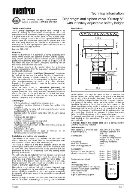
Dimensions:<br />
Ø fl 67.5<br />
4 Plombier- holes for lead<br />
sealing ffnungen at the<br />
handwheel<br />
am Handrad<br />
<strong>anti</strong>clockwise until stop. As soon as the oil reaches the<br />
burner, the required safety height is set at the scale (equivalent<br />
to ∆hv in the illustrated example). Should a non-return<br />
check <strong>valve</strong> have been installed (without pressure balance),<br />
the setting of the safety height has to be carried out before<br />
installing the <strong>valve</strong> or when the burner is in operation. To<br />
check the chosen safety height, a leakage is simulated at the<br />
lowest point of the suction pipe (e.g. by loosening the flexible<br />
hoses of the burner or the filter cup). At the leakage point, no<br />
oil coming from the tank may escape. If it does, the safety<br />
height should be increased until no more oil escapes.<br />
To prevent unauthorized tampering, the setting may be<br />
lead sealed at the handwheel. The <strong>valve</strong> now functions<br />
automatically.<br />
A leakage test of the suction pipe up to 6 bar is possible<br />
with the <strong>valve</strong> being installed.<br />
<strong>Technical</strong> data:<br />
Flow capacity at pressure loss: max. 200 l/h at 40 mbar<br />
Safety height ∆ hv adjustable between 1 m<br />
and 4 m<br />
Connection:<br />
3 ⁄8” female thread,<br />
suitable for compression<br />
fittings 6, 8, 10, 12 mm<br />
Positioning: preferably horizontal<br />
Max. test pressure: 6 bar<br />
Max. working pressure:<br />
Accessories:<br />
40 °C<br />
Connection sets for copper 6 mm Item 212 70 50<br />
pipes (compression fittings) 8 mm Item 212 70 51<br />
10 mm Item 212 70 52<br />
12 mm Item 212 70 53<br />
Sealing wire with lead<br />
Tests:<br />
TÜV tested (S 04/01)<br />
10 pces. Item 108 90 91<br />
according to DIN EN 12514 part 2.<br />
General construction supervising<br />
admission by DIBt<br />
Z-65.50-305.<br />
Sign of conformity (Sign Ü)<br />
1/2002 9.2-1<br />
90<br />
3 G ⁄8 3/8" ”<br />
absperren<br />
4<br />
3<br />
2<br />
1m<br />
entlueften<br />
59.5<br />
Ø fl 36<br />
69 abt. ca. 40 40
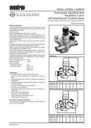
Max. length of suction pipe [m]<br />
The chart below is a guide to the maximum length of the<br />
suction pipe depending on the flow capacity of the oil and<br />
the inner pipe diameter. It is assumed that the safety height<br />
The stated values are valid for a suction pipe without pipe<br />
bends/elbows, including the resistance values of the <strong>valve</strong>s<br />
(diaphragm <strong>anti</strong> <strong>siphon</strong> <strong>valve</strong> and filter/”Toc-Duo”) illustrated<br />
in the example of installation. When using the maximum<br />
possible length of the suction pipe, then the burner pump<br />
has to produce an underlying pressure of about –0.4 bar.<br />
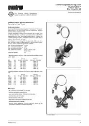
Example of installation:<br />
”Flexo-Bloc”<br />
Tank<br />
Subject to technical modification without notice.<br />
Product range 9<br />
ti 101-1/10/10.2001/MW.<br />
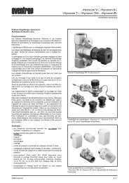
<strong>Diaphragm</strong> <strong>anti</strong> <strong>siphon</strong> <strong>valve</strong> ”Oilstop V”<br />
In two pipe systems:<br />
Return pipe with<br />
free drain-off in the tank<br />
inner pipe diameter<br />
10 mm<br />
Suction pipe<br />
Return pipe<br />
Suction pipe<br />
OVENTROP UK LTD.<br />
Unit I – The Loddon Centre<br />
Wade Road<br />
Basingstoke, Hampshire RG24 8FL<br />
Telephone (01256) 330441<br />
Telefax (Sales) (01256) 330525<br />
Telefax (General) (01256) 470970<br />
E-Mail sales@oventrop.co.uk<br />
set at the handwheel corresponds to the actual height<br />
difference ∆hv.<br />
inner pipe diameter 13 mm<br />
Flow capacity of oil [l/h]<br />
Pipe bends/elbows, isolation- and change-over <strong>valve</strong>s or<br />
other installations in the suction pipe between the diaphragm<br />
<strong>anti</strong> <strong>siphon</strong> <strong>valve</strong> and the burner as well as oil of low<br />
temperature (underground tanks, unheated storage rooms,<br />
pipes installed outside, etc.) will mean additional pressure<br />
loss. Any such installations can reduce the maximum<br />
possible length of the suction pipe considerably, when<br />
compared with the values illustrated in the chart.<br />
”Toc-Duo”<br />
Burner<br />
Burner<br />
F. W. OVENTROP GmbH & Co. KG<br />
Paul-<strong>Oventrop</strong>-Straße 1<br />
D-59939 Olsberg<br />
Telephone (02962) 82-0<br />
Telefax (02962) 82405<br />
Internet http://www.oventrop.de<br />
eMail mail@oventrop.de<br />
9.2-2 1/2002<br />
Filter<br />
One pipe system<br />
Two pipe system<br />
∆h v (safety height) 1 to 4 m<br />
Max. length of suction pipe [m]