Table of Tables - METRANS Transportation Center
Table of Tables - METRANS Transportation Center
Table of Tables - METRANS Transportation Center

You also want an ePaper? Increase the reach of your titles
YUMPU automatically turns print PDFs into web optimized ePapers that Google loves.
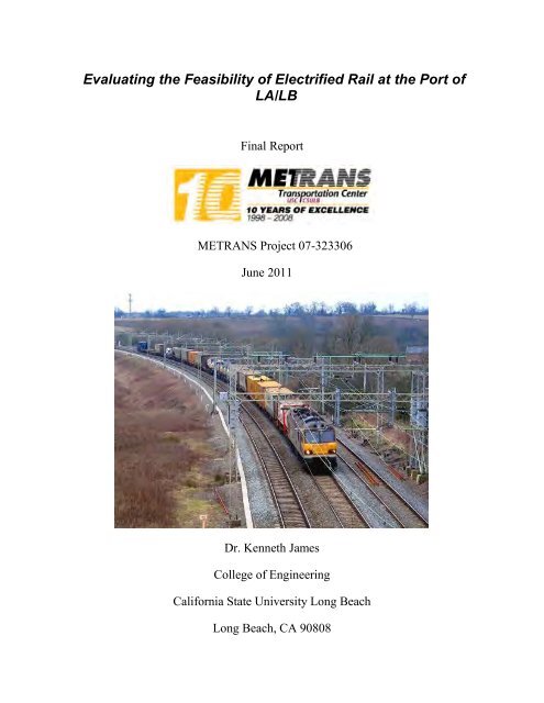
Evaluating the Feasibility <strong>of</strong> Electrified Rail at the Port <strong>of</strong><br />
LA/LB<br />
Final Report<br />
<strong>METRANS</strong> Project 07-323306<br />
June 2011<br />
Dr. Kenneth James<br />
College <strong>of</strong> Engineering<br />
California State University Long Beach<br />
Long Beach, CA 90808
Evaluating the Feasibility <strong>of</strong> Electrified Rail at the<br />
Port <strong>of</strong> LA/LB<br />
Disclaimer<br />
The contents <strong>of</strong> this report reflect the views <strong>of</strong> the authors, who are responsible for the<br />
facts a nd t he a ccuracy <strong>of</strong> t he i nformation pr esented h erein. T his doc ument i s<br />
disseminated unde r t he sponsorship <strong>of</strong> t he D epartment <strong>of</strong> T ransportation, U niversity<br />
<strong>Transportation</strong> C enters Program, a nd C alifornia D epartment o f T ransportation i n t he<br />
interest <strong>of</strong> i nformation e xchange. T he U .S. G overnment a nd C alifornia Department <strong>of</strong><br />
<strong>Transportation</strong> assume no liability for the contents or use there<strong>of</strong>. The contents do not<br />
necessarily r eflect the <strong>of</strong>ficial vi ews or pol icies <strong>of</strong> the S tate <strong>of</strong> C alifornia or the<br />
Department <strong>of</strong> <strong>Transportation</strong>. This report does not constitute a standard, specification,<br />
or regulation.<br />
ii
Evaluating the Feasibility <strong>of</strong> Electrified Rail at the<br />
Port <strong>of</strong> LA/LB<br />
Abstract<br />
Electrifying r ail at t he P orts <strong>of</strong> Los Angeles and Long Beach has t he potential to both<br />
replace t he c ongestion a nd pol lution <strong>of</strong> dr ayage trucks, a nd t he pol lution <strong>of</strong> r ail. T he<br />
electrification process was analyzed in light <strong>of</strong> costs, utility, and safety. The length <strong>of</strong><br />
rail considered for replacing drayage trucks is about 12 miles at the Ports <strong>of</strong> LA and LB<br />
to connect terminal clusters to the UP ICTF, and an additional 20 miles <strong>of</strong> a single line<br />
along the Alameda corridor to the BNSF Hobart yard; assuming the SCIG is not built.<br />
Cost <strong>of</strong> retr<strong>of</strong>itting conventional rail with at-ground third rail is from $1.42M to $1.5M<br />
per mile verses $.825M to $1.5M per mile for overhead caternary; excluding the costs <strong>of</strong><br />
new or r etr<strong>of</strong>it loc omotives—from $2M t o $5M e ach, a nd a dditional e lectric pow er<br />
distribution requirements for more tractive power. Operational decisions by the class one<br />
rails regarding “switch out” to Diesel power for transcontinental runs will determine the<br />
number <strong>of</strong> ne w or m odified l ocomotives r equired; a nd t he l ength ( weight) <strong>of</strong> s huttle<br />
trains w ill de termine the pow er di stribution c osts. Neither at -grade t hird r ail nor<br />
overhead c aternary a re c onducive t o t rain f ormation i nvolving l oading, unl oading, a nd<br />
numerous short switched sidings. H owever, operational requirements such a switching<br />
and pow er r equirements f avor ove rhead c aternary, m aking i t t he b etter a pproach for<br />
hauling train sections or shuttle trains from the port to Diesel pulled transcontinental train<br />
Intermodal. Safety requirements also infer overhead lines are the better way for retr<strong>of</strong>it<br />
electrification.<br />
iii
Evaluating the Feasibility <strong>of</strong> Electrified Rail at the<br />
Port <strong>of</strong> LA/LB<br />
<strong>Table</strong> <strong>of</strong> Contents<br />
Disclaimer ........................................................................................................................... ii<br />
Abstract ....………………………………………………………………………………iii<br />
<strong>Table</strong> <strong>of</strong> Contents ............................................................................................................... iv<br />
<strong>Table</strong> <strong>of</strong> Figures .................................................................................................................. v<br />
<strong>Table</strong> <strong>of</strong> <strong>Table</strong>s ................................................................................................................... v<br />
Disclosure .......................................................................................................................... vi<br />
Acknowledgments .............................................................................................................. vi<br />
1 Introduction ................................................................................................................. 1<br />
2 Quantify Existing and Planned Rail Lengths at the Ports <strong>of</strong> San Pedro Bay .............. 3<br />
2.1 Cumulative Length <strong>of</strong> Switched Siding Rail at Major Terminals ...................... 3<br />
2.2 Length <strong>of</strong> Existing Rail to Replace Drayage Trucks to the UP ICTF and<br />
Proposed BNSF SGIG ........................................................................................ 3<br />
2.3 Length <strong>of</strong> Rail to Hobart Yard from Proposed BNSF SGIG Location to<br />
Downtown Hobart Yard ...................................................................................... 4<br />
3 Electrification Technologies ....................................................................................... 4<br />
3.1 Third-Rail Approach to Electrification ............................................................... 4<br />
3.2 Overhead Caternary Retr<strong>of</strong>it Material and Installation Costs Conventional ...... 7<br />
3.3 Third-Rail and Overhead Caternary Approach to “Diesel” Locomotive Retr<strong>of</strong>it<br />
........................................................................................................................... 10<br />
3.4 Power Distribution ............................................................................................ 11<br />
4 Operational Considerations and Comparisons <strong>of</strong> Diesel Driven Freight to Both Third<br />
Rail and Overhead Caternary Retr<strong>of</strong>it Freight Electrification .......................... 13<br />
4.1 Operational Characteristics <strong>of</strong> Third Rail Systems and Their Applicability to<br />
Freight Handling ............................................................................................... 14<br />
4.2 Operational Characteristics <strong>of</strong> Overhead Caternary Systems and Their<br />
Applicability to Freight Handling ..................................................................... 15<br />
5 Cost Estimate Summary for Third-Rail and Overhead Caternary Retr<strong>of</strong>it to<br />
Conventional Rail Infrastructure ....................................................................... 15<br />
5.1 Estimate <strong>of</strong> Third-Rail Retr<strong>of</strong>it per Mile .......................................................... 16<br />
5.2 Estimate <strong>of</strong> Overhead Caternary Retr<strong>of</strong>it per Mile ........................................... 18<br />
5.3 Estimate <strong>of</strong> Single Diesel-Electric Locomotive Conversion to Hybrid Electric<br />
Locomotive for Third-Rail and/or Overhead Caternary Operation .................. 19<br />
5.4 Estimate <strong>of</strong> Electric Grid Substation and Block Electric Distribution ............. 20<br />
6 Conclusions and Recommendations ......................................................................... 21<br />
7 References ................................................................................................................. 23<br />
Appendix A ...................................................................................................................... A1<br />
Appendix B ....................................................................................................................... B1<br />
Appendix C ....................................................................................................................... C1<br />
Appendix D ...................................................................................................................... D1<br />
iv
Evaluating the Feasibility <strong>of</strong> Electrified Rail at the<br />
Port <strong>of</strong> LA/LB<br />
<strong>Table</strong> <strong>of</strong> Figures<br />
Figure 1- Several Forms <strong>of</strong> Third Rail – Shoe Contact in Order <strong>of</strong> Safety and Expense<br />
(least to most safe and expensive) ...................................................................... 5<br />
Figure 2- Example <strong>of</strong> a Bottom Contact Shoe ................................................................ 6<br />
Figure 3- Pantograph on the Acela Contacting Power Wire Supported from Overhead<br />
Caternary (“Messenger Wire”) by “Droppers” ................................................... 7<br />
Figure 4- Modern Singe Phase AC Locomotive with Single Phase AC Caternary Power<br />
Converted to 3-Phase Power For the Motors (Inset) .......................................... 8<br />
Figure 5- Overhead Contact System Two Track ............................................................ 9<br />
Arrangement with <strong>Center</strong> Pole Construction .................................................................. 9<br />
Figure 6- Overhead Contact System Typical Portal Arrangement ................................. 9<br />
Figure 7- Typical “Deisel Electric” Locomotive Prevalent on US Freight and<br />
Passenger Rail ................................................................................................... 10<br />
Figure 8- Examples <strong>of</strong> Hybrid Locomotives for Use on Electrified Rail ..................... 11<br />
Figure 9- Typical Layout <strong>of</strong> a Third Rail Power Distribution System ......................... 12<br />
Figure 10- Detailed Schematic <strong>of</strong> Proposed 25 kV Overhead Caternary Electification13<br />
<strong>Table</strong> <strong>of</strong> <strong>Table</strong>s<br />
<strong>Table</strong> 1- Capital Cost Breakdown <strong>of</strong> the BART Thrird Rail System ........................... 17<br />
<strong>Table</strong> 2-Third Rail Electrification Estimate for CalTrain ............................................. 18<br />
<strong>Table</strong> 3- Rough Order <strong>of</strong> Magnitude (ROME) analysis <strong>of</strong> the Oshawa to Hamilton<br />
Station section <strong>of</strong> the Toronto Lakeshore Line electrification retr<strong>of</strong>it ............. 19<br />
v
Evaluating the Feasibility <strong>of</strong> Electrified Rail at the<br />
Port <strong>of</strong> LA/LB<br />
Disclosure<br />
The contents <strong>of</strong> this report reflect the views <strong>of</strong> the authors, who are responsible for the<br />
facts a nd t he a ccuracy <strong>of</strong> t he i nformation pr esented h erein. T his doc ument i s<br />
disseminated unde r t he sponsorship <strong>of</strong> t he D epartment <strong>of</strong> T ransportation, U niversity<br />
<strong>Transportation</strong> <strong>Center</strong>s Program, a nd C alifornia D epartment o f T ransportation i n t he<br />
interest <strong>of</strong> i nformation e xchange. T he U .S. G overnment a nd C alifornia Department <strong>of</strong><br />
<strong>Transportation</strong> assume no liability for the contents or use there<strong>of</strong>. The contents do not<br />
necessarily r eflect the <strong>of</strong>ficial vi ews or pol icies <strong>of</strong> the S tate <strong>of</strong> C alifornia or the<br />
Department <strong>of</strong> <strong>Transportation</strong>. This report does not constitute a standard, specification,<br />
or regulation.<br />
Acknowledgments<br />
The a uthors a cknowledge t he he lpful a ssistance <strong>of</strong> M r. Herman M adden, D irector o f<br />
Operations at the Union Pacific ICTF, Mr. Kerry Cartwright <strong>of</strong> the Port <strong>of</strong> Los Angeles,<br />
and Mr. Michael Orn with the Los Angeles Department <strong>of</strong> Water and Power (LADWP)<br />
for many helpful discussions.<br />
vi
Evaluating the Feasibility <strong>of</strong> Electrified Rail at the<br />
Port <strong>of</strong> LA/LB<br />
1 Introduction<br />
Goods movement through the Ports <strong>of</strong> San Pedro has bogged down in recent years due to<br />
truck c ongestion c aused b y t he r apid i ncrease i n c ontainer t raffic and t he l ocal<br />
communities’ understandable reluctance to accept added pollution that accompanies port<br />
growth. The immediate solution for truck congestion is near-dock rail. T he solution to<br />
the air and noise pollution caused by increased rail movement is rail electrification. The<br />
objective <strong>of</strong> this project was to analyze the cost and feasibility <strong>of</strong> available, standardized<br />
equipment for rail e lectrification retr<strong>of</strong>it in t he LA ba sin, a nd to better de fine i ssues<br />
involved in electrified “shuttle-trains” for both commercial a nd military goods<br />
movement.<br />
This project w as t o determine t he utility <strong>of</strong> bl ock switched, third rail e lectrification <strong>of</strong><br />
existing and planned near-dock rail at the Port <strong>of</strong> LA/LB using comparisons with existing<br />
and proposed rail electrification projects in other locals. Determination <strong>of</strong> feasibility was<br />
based on consideration <strong>of</strong> t hree general i ssues i nvolved i n t he t ransition f rom<br />
conventional t o e lectrified r ail: ( 1) or der <strong>of</strong> m agnitude c apital and op erational c ost<br />
projections, ( 2) pr ojected ope rational ut ility f or ne ar-dock a nd s hort ha ul, a nd ( 3)<br />
projected ope rational s afety. Initially, t he p roposed s tudy, s idestepped ove rhead<br />
caternary electrification in favor <strong>of</strong> on-ground third rail due to the apparent awkwardness<br />
<strong>of</strong> overhead lines at port complexes; however, recent developments in Europe where the<br />
caternary can be powered down and swung clear <strong>of</strong> the track have mitigated this concern.<br />
However, e ven w ith t he a dded consideration <strong>of</strong> overhead c aternary, w e conclude, t hat<br />
neither electrification approach is practical for near-dock rail retr<strong>of</strong>it; but due to economy<br />
and safety, overhead electrification is the more practical <strong>of</strong> the two approaches to retr<strong>of</strong>it<br />
freight rail away from and beyond the port complex.<br />
The approach to this pr oject f or de termining the c ost a nd utility <strong>of</strong> electrification for<br />
existing a nd pl anned ne ar-dock r ail a t t he P ort <strong>of</strong> LA/LB c onsisted <strong>of</strong> t hree tasks: (1)<br />
determining the length <strong>of</strong> rail to be considered for electrification; (2) the material cost <strong>of</strong><br />
electrification including rail r etr<strong>of</strong>it, locomotive modi fication, and power di stribution;<br />
and (3) the operational considerations <strong>of</strong> retr<strong>of</strong>it electrification.<br />
Task 1: The length <strong>of</strong> r ail s ubject to possible electrification for Diesel pollution<br />
mitigation was quantified. Near-dock rail was assumed to consist <strong>of</strong> rail sidings at major<br />
terminals in both ports as well as rail on property managed by the Ports and used by the<br />
class-one r ails t o a ccess t he t erminals. T o r espond t o Diesel pollution pr oduced b y<br />
moving cargo out <strong>of</strong> ports, the rail lines to the UP ICTF and the proposed BNSF SCIG<br />
were included as candidates for electrification. Since the BNSF SCIG is only proposed,<br />
the length <strong>of</strong> a single line <strong>of</strong> the Alameda Corridor to the downtown Hobart yards was<br />
also included.<br />
1
Evaluating the Feasibility <strong>of</strong> Electrified Rail at the<br />
Port <strong>of</strong> LA/LB<br />
Task 2: The “per-mile” cost estimate <strong>of</strong> electrifying rail involved the material and retr<strong>of</strong>it<br />
costs a nd t he a dded i nstallation c osts <strong>of</strong> electrical di stribution systems inc luding a<br />
possible integrated train control (ITC) network. The third-rail approach to electrification<br />
as described here consists <strong>of</strong> the configuration <strong>of</strong> the third rail and the system <strong>of</strong> switched<br />
power distribution to the third rail to add safety to a system best applied to those with no<br />
pedestrian or vehicle access. The overhead caternary approach was included in the cost<br />
estimate since its utility and safety were deemed competitive if not superior to at-ground<br />
third rail.<br />
Major manufacturers <strong>of</strong> Diesel-electric locomotives have bui lt e ngines c onfigured w ith<br />
“shoe” or pantograph collectors to switch electric motor drive from the on-board Diesel<br />
generator to electric utility; a second cost factor, the costs <strong>of</strong> modifying locomotives was<br />
also considered. If the locomotives are intended to switch from electric grid power to onboard<br />
Diesel power for long haul, then many locomotives in the fleet must be expensive,<br />
“dual-use” el ectrification and Diesel. I f electric driven locomotives are us ed locally a t<br />
the Ports and then switched out with Diesel locomotives for long-haul t ranscontinental<br />
runs, then a s maller number <strong>of</strong> el ectric dr iven l ocomotives—either thi rd-rail or<br />
caternary—are n eeded. Also, de pending on r ail system operating pl ans, the t hird c ost<br />
factor <strong>of</strong> electrical distribution depends on how much power is required. T rain lengths<br />
used presently will require extensive and robust electrical distribution where as shorter,<br />
“shuttle trains” will require less infrastructure.<br />
Task 3: T he m any pr os a nd c ons <strong>of</strong> t he a pplicability o f r ail e lectrification a t t he P ort<br />
involve not only the construction costs, but also operational considerations and possible<br />
costs <strong>of</strong> di sruption <strong>of</strong> o perations dur ing c onstruction. M inor s hifts i n r ail ope rations,<br />
added safety issues, and added electrical generation all need to be considered, along with<br />
the expected benefits <strong>of</strong> reduction <strong>of</strong> pollution and congestion.<br />
The likely near-dock siding lengths, terminals to intermodal rail distances, and Alameda<br />
Corridor to Hobart distances were all determined as described Section 2 with supporting<br />
data detailed in Appendix A. Basic third rail and caternary retr<strong>of</strong>it technologies such as<br />
power distribution, locomotive power pickup, grounding approaches, as well as current<br />
and voltage waveforms and levels are broadly described in Section 3. Characteristics <strong>of</strong><br />
the t wo e lectrification approaches a nd t heir application t o por t a nd ur ban f reight<br />
movement compared with conventional Diesel-pulled trains are discussed in Section 4.<br />
Section 5 presents t he cos ts pe r m ile <strong>of</strong> t he at -ground, t hird r ail that were ba sed on<br />
extrapolation <strong>of</strong> electrification costs for proposed a nd recently constructed, t ransit<br />
systems using third rails. While these referenced systems were designed for passengers<br />
and not f reight; t ractive pow er <strong>of</strong> t hese s ystems i s a ppropriate f or m oving s hort t rain<br />
sections in switching operations. Overhead caternary costs were based on proposed and<br />
actual rail retr<strong>of</strong>its <strong>of</strong> Diesel-pulled light rail systems (Appendix B); reduced concern <strong>of</strong><br />
arcing in these systems provides for sufficient tractive power to move shuttle and longer<br />
trains. Cost pe r mile e stimates a nd electric loc omotive e stimates are supported w ith<br />
details f rom Appendices B and C. Tractive p ower di stribution c osts and l ocomotive<br />
retr<strong>of</strong>it c osts for both electrification approaches a re s imilar under s imilar ope rating<br />
2
Evaluating the Feasibility <strong>of</strong> Electrified Rail at the<br />
Port <strong>of</strong> LA/LB<br />
conditions. Finally, Section 6 provides conclusions as to the feasibility <strong>of</strong> rail retr<strong>of</strong>it at<br />
the Ports and considers the drawbacks to the third rail system compared to the overhead<br />
caternary as well as “strawman” estimate for a shuttle train from a number <strong>of</strong> clustered<br />
port terminals to the ICTF to replace truck drayage.<br />
2 Quantify Existing and Planned Rail Lengths at the Ports <strong>of</strong> San<br />
Pedro Bay<br />
An initial s tep to evaluating the feasibility o f electrification <strong>of</strong> r ail at the P ort is to<br />
estimate the number <strong>of</strong> miles <strong>of</strong> track that should be considered. Considerable port rail is<br />
in the terminals and ideally used to form Diesel-pulled transcontinental container trains<br />
out <strong>of</strong> t he LA ba sin and is not a c andidate for el ectrification. A l arge vol ume <strong>of</strong><br />
containers requires truck drayage to intermodal rail yards for loading on transcontinental<br />
trains. Electrified rail to replace t hese dr ayage trucks i s mainly on P ort property,<br />
providing a proposed BNSF intermodal yard can be built near the Port. If not, rail may<br />
need to be electrified to dow ntown LA to where a la rge int ermodal f acility pr esently<br />
operates. The total length <strong>of</strong> rail finally being considered is around 32 miles.<br />
2.1 Cumulative Length <strong>of</strong> Switched Siding Rail at Major Terminals<br />
The P orts <strong>of</strong> Los A ngeles a nd Long Beach ha ve no, t rue on -dock r ail i n t hat s hipping<br />
containers are not loaded directly on a railcar from the ship, but rather “hustled” from the<br />
overhead dr op to te mporary s torage o r te rminal f acilities f or tr ansfer to a tr uck or a<br />
railcar. The transfer to a railcar is made at terminal operated rail spurs where containers<br />
with a common destination are loaded on short sections <strong>of</strong> trains. The sections might stay<br />
on terminal property for several days while the sections are filled before they are moved<br />
to areas <strong>of</strong> the port with where rail length is sufficient to form full trains for transport<br />
along the Alameda corridor and unto the continental US (CONUS). Lack <strong>of</strong> sufficient<br />
rail a t the te rminals a nd por ts ma ke f orming full l ength trains aw kward thus r equiring<br />
containers t o be d rayed b y truck t o rail yards such as t he U P’s ICTF or the B NSF’s<br />
Hobart yard where they are loaded on railcars to form full trains for CONUS. As shown<br />
in Appendix A, the a ccumulated track at the m ajor terminals in both p orts is about 32<br />
miles. Due to terminal congestion this at-dock rail is likely not a cost effective candidate<br />
for electrification. However, shuttle trains using electrified rail from localized clusters <strong>of</strong><br />
terminals to the aforementioned intermodals could replace drayage trucks.<br />
2.2 Length <strong>of</strong> Existing Rail to Replace Drayage Trucks to the UP ICTF<br />
and Proposed BNSF SGIG<br />
Presently, thousands <strong>of</strong> drayage trucks carry containers that cannot be loaded on rail in<br />
the terminals either to the UP’s Intermodal Container Transfer Facility (ICTF) close to<br />
the Port or to the BNSF’s Hobart Yard (and others) in downtown LA. R eplacing those<br />
drayage t rucks w ith s hort s huttle t rains requires c onnecting t he p reviously d escribed<br />
terminal r ail clusters to the se int ermodal f acilities. T he di stance to the dow ntown<br />
3
Evaluating the Feasibility <strong>of</strong> Electrified Rail at the<br />
Port <strong>of</strong> LA/LB<br />
railyards ha s pr ompted t he pr oposal <strong>of</strong> a ne w i ntermodal ne ar t he P ort; t he S outhern<br />
California I nternational Gateway (SCIG). T he distance <strong>of</strong> e lectrification <strong>of</strong> r ail from<br />
terminals to both the existing and proposed port intermodals is approximately 12 miles.<br />
2.3 Length <strong>of</strong> Rail to Hobart Yard from Proposed BNSF SGIG Location<br />
to Downtown Hobart Yard<br />
If t he S CIG is not constructed, the container shuttle trains replacing the drayage trucks<br />
would be forming transcontinental trains at the downtown yards. The additional length <strong>of</strong><br />
electrification retr<strong>of</strong>it could be at least two <strong>of</strong> the three rail lines in the Alameda corridor<br />
which is a length <strong>of</strong> about 20 m iles for a total electrification retr<strong>of</strong>it length <strong>of</strong> about 32<br />
miles <strong>of</strong> typically double tracked electrification.<br />
3 Electrification Technologies<br />
There are two common approaches to retr<strong>of</strong>itting existing rail systems. One is the “third<br />
rail” method where an at-ground, power-carrying rail is placed between or just outside <strong>of</strong><br />
the two guiding rails; the locomotive connects to the third rail through physical contact<br />
with the third rail by a “shoe” at ground level. The other approach uses a power carrying<br />
overhead caternary that the locomotive makes electrical contact through a pantograph on<br />
top <strong>of</strong> t he l ocomotive. Most e lectrification systems us e ove rhead wires s o that the<br />
electric pow er is r elatively far f rom the int rinsic ground return <strong>of</strong> t he r ails t o pr event<br />
arcing and hence deliver more electrical power; so at-ground third rail is an option up to<br />
only about 1.2 kV . Section 3.1 de scribes t he third rail t echnology approach t o<br />
electrification while Section 3.2 addresses the overhead caternary technology.<br />
The “Diesel” locomotives, operating in the Los Angeles basin and throughout the country<br />
in freight and passenger service carry their own electrical power supply, and so are free <strong>of</strong><br />
the r equirement for a “s hoe” cont acting a pow ered t hird-rail, or a pantograph c ontacting<br />
power l ines ove rhead. T his f reedom from the ne cessity t o connect to a n a dditional<br />
electrical distribution source has caused the almost total elimination <strong>of</strong> electric rail in favor<br />
<strong>of</strong> this less cum bersome “electrification” s ource f or f reight a pplications. S ection 3.3<br />
describes the technology <strong>of</strong> r etr<strong>of</strong>itting “Diesel” locomotives t o us e t he e lectric grid.<br />
Finally Section 3.4 describes a standard power distribution structure common to both third<br />
rail and overhead caternary electric rail systems.<br />
3.1 Third-Rail Approach to Electrification<br />
Third rail current collection comes in a variety <strong>of</strong> designs. The simplest is what is called<br />
"top contact" because that’s the part <strong>of</strong> the rail upon which the pick-up shoe slides. Being<br />
the simplest and oldest third rail approach, its drawbacks are well documented. First and<br />
foremost is the safety risk <strong>of</strong> the exposed electric conductor. T he second obvious issue is<br />
the col lecting o f i ce and l eaves dur ing ba d weather r ender top c ontact thi rd rail s ystems<br />
almost unw orkable unl ess e xpensive r emedies are carried out as s hown i n F igure 1 .<br />
Bottom contact is best - you can cover effectively most <strong>of</strong> the rail and it is protected from<br />
the worst elements <strong>of</strong> the environment. Bottom contact shoes are spring loaded to provide<br />
4
Evaluating the Feasibility <strong>of</strong> Electrified Rail at the<br />
Port <strong>of</strong> LA/LB<br />
the necessary cont act force. An example <strong>of</strong> a bottom cont act shoe as used on a German<br />
metro line is shown in the photo <strong>of</strong> Figure 2. Mechanical or pneumatic systems have been<br />
devised to make it possible to disconnect shoes from the third rail remotely from the cab.<br />
Figure 1- Several Forms <strong>of</strong> Third Rail – Shoe Contact in Order <strong>of</strong> Safety and<br />
Expense (least to most safe and expensive)<br />
5
Evaluating the Feasibility <strong>of</strong> Electrified Rail at the<br />
Port <strong>of</strong> LA/LB<br />
Figure 2- Example <strong>of</strong> a Bottom Contact Shoe<br />
Note tha t like ot her c ommercial electric tr ansmission systems e lectric r ail s ystems<br />
typically ha ve a s ingle c onductor pow er f eed ( third r ail—shoe i n this cas e) and a<br />
“ground” r eturn. F or a n el ectrified rail s ystem the return is typically the wheel to rail<br />
connection, and since the track is not necessarily contiguous, the natural contact <strong>of</strong> rail to<br />
earth l ikely f orms t he f inal r eturn p ath. W hen such a c onvenient return circuit c ould<br />
produce unsafe potential gradients, a “fourth rail” is added as the return as done in several<br />
systems. The London Underground and Vancouver’s Sky Train are both third and fourth<br />
rail systems using two rails: one for power distribution and one for return.<br />
Most di stributed commercial el ectric po wer i s A C r ather than the mor e di fficult to<br />
distribute (until recently) DC power. While use <strong>of</strong> a third rail does not require the use <strong>of</strong><br />
DC, in practice all third-rail systems use DC because it can carry 41% more power than<br />
an AC s ystem ope rating at t he s ame pe ak voltage. M aximizing the power for t he arclimited<br />
third rail geometry has kept DC as the dominate power distribution waveform.<br />
6
Evaluating the Feasibility <strong>of</strong> Electrified Rail at the<br />
Port <strong>of</strong> LA/LB<br />
3.2 Overhead Caternary Retr<strong>of</strong>it Material and Installation Costs<br />
Conventional<br />
Third rail s ystems requiring a t-ground foundation a nd s ubstantial m etallic c onductors<br />
seemingly cost more for materials and installation than simply stringing overhead wires<br />
between distant poles for a cat ernary rail electrification system. The difference in cost<br />
however is not that great; due to the fact that contact between the overhead wire and the<br />
pantograph on t he l ocomotive i s not a s imple arrangement. T he mechanical cont act<br />
between the spring loaded pantograph and the hanging power wire is difficult to maintain<br />
due t o physical waves set up in the w ire. M ultiple pa ntographs pe r tr ain mitigate<br />
intermittent contacts. Maintaining a level power wire requires significant tension which<br />
for s imple s ystems limit s the s pacing <strong>of</strong> th e c aternary s upports. In order to space t he<br />
supports f urther apart a nd he nce i mprove economy, m odern e lectrified rail us es a t rue<br />
caternary a s a s upport f or t he pow er w ire m uch l ike a s uspension br idge supports a<br />
roadway. “Droppers” and “stitches” support the power line from the caternary as shown<br />
in the photo <strong>of</strong> the Acela, Boston to Washington train in Figure 3.<br />
Figure 3- Pantograph on the Acela Contacting Power Wire Supported from<br />
Overhead Caternary (“Messenger Wire”) by “Droppers”<br />
Early overhead caternary systems used DC transmission and DC traction motors similar<br />
to third rail s ystems; h owever, e ase <strong>of</strong> tr ansmission a nd t he a forementioned hi gher<br />
voltage c apacity ha s c aused A C t o be come t he pr evalent f orm <strong>of</strong> e lectrification f or<br />
overhead caternary rail electrification.<br />
7
Evaluating the Feasibility <strong>of</strong> Electrified Rail at the<br />
Port <strong>of</strong> LA/LB<br />
In addition, modern 3-phase AC motors have proven more efficient and as easy to control<br />
as DC motors. Thus 3-phase AC motors are prevalent in modern overhead caternary rail<br />
systems. However, like 3-phase electric grid power transmission, three separate wires are<br />
required t o dr ive t hese AC m otors and t his i mplies t hree ove rhead wires a nd t hree<br />
pantographs; a situation that presents insurmountable difficulties in practice. Thus single<br />
phase transmission is the lone caternary po wer supply as shown in Figure 3.1, and the<br />
single phase is converted to 3-phase on board for the 3-phase motors as shown in inset to<br />
Figure 4. Even two separate caternary wires—one power, one return—are not used in<br />
practice due t o t he di fficulty o f m aintaining contact i n a t wo wire, t wo pa ntograph<br />
geometry.<br />
Figure 4- Modern Singe Phase AC Locomotive with Single Phase AC Caternary<br />
Power Converted to 3-Phase Power For the Motors (Inset)<br />
Unlike third rail where each track has its own power rail, multiple tracks can share the<br />
same cat ernary s upport structure, hence slightly reducing cos t if mul tiple, parallel r ail<br />
lines ar e retr<strong>of</strong>it. S ome a pproaches <strong>of</strong> electrifying m ultiple t racks a re not ed i n t he<br />
Figures 5 and 6.<br />
8
Evaluating the Feasibility <strong>of</strong> Electrified Rail at the<br />
Port <strong>of</strong> LA/LB<br />
Figure 5- Overhead Contact System Two Track<br />
Arrangement with <strong>Center</strong> Pole Construction<br />
Figure 6- Overhead Contact System Typical Portal Arrangement<br />
9
Evaluating the Feasibility <strong>of</strong> Electrified Rail at the<br />
Port <strong>of</strong> LA/LB<br />
3.3 Third-Rail and Overhead Caternary Approach to “Diesel”<br />
Locomotive Retr<strong>of</strong>it<br />
The so-called “Diesel” locomotives, operating in the Los Angeles basin and throughout the<br />
country in freight and passenger service, are not like Diesel trucks, in that the Diesel engine<br />
is the power source but not the motive force. If a Diesel locomotive operated like a truck<br />
does, a massive (and inefficient) mechanical transmission would be required to couple the<br />
engine’s pow er t o t he wheels. Instead, a l ocomotive’s Diesel engine dr ives an electric<br />
generator which in turn powers electric motors directly coupled to the wheels as shown in<br />
Figure 7.<br />
Figure 7- Typical “Diesel Electric” Locomotive Prevalent on US Freight and<br />
Passenger Rail<br />
The electric motors in these Diesel-electric locomotives transmit power to the wheels, as<br />
well as add weight to the locomotive for more traction. These locomotives carry their own<br />
electrical pow er s upply, and so are f ree o f t he r equirement for a “s hoe” c ontacting a<br />
powered third-rail, or a pantograph contacting power lines overhead. This freedom from<br />
the necessity to connect to an additional electrical distribution source has caused the almost<br />
total elimination <strong>of</strong> electric rail in favor <strong>of</strong> this less cumbersome “electrification” source for<br />
freight applications.<br />
However, some applications exist that require hybrid “electro-Diesel” systems. Freight and<br />
passenger r ail systems near N ew Y ork City ut ilize Diesel generators on t wo-rail tr acks<br />
through Long Island and Connecticut, but when entering the rail tunnels in the vicinity <strong>of</strong><br />
the city, the locomotives drop a hydraulic “shoe” onto a powered third-rail and discontinue<br />
generating el ectric pow er w ith Diesel engines to c onform t o or dinances pr ohibiting<br />
locomotives from emitting smoke within the tunnels. S uch “electro-Diesel” locomotives<br />
have been manufactured by both General Electric and General Motors (see Figure 8).<br />
10
Evaluating the Feasibility <strong>of</strong> Electrified Rail at the<br />
Port <strong>of</strong> LA/LB<br />
A " dual-mode" P32AC-DM locomotive w as d eveloped by<br />
General Electric to run its electric motors on power from the<br />
onboard Diesel engine or from a third rail carrying 750 volts<br />
<strong>of</strong> direct c urrent and s eamlessly tr ansition between th e two<br />
modes while underway. The P32AC-DM is unique n ot only<br />
because o f t hird-rail c apability, b ut also b ecause i t i s<br />
equipped with AC (alternating current) traction motors.<br />
11<br />
The EMD FL9 (New H aven C lass E DER-5) w as a du alpower<br />
electro-Diesel locomotive, cap able o f s elf-powered<br />
Diesel-electric operation and o f o peration a s a n electric<br />
locomotive powered f rom a third r ail. A t otal o f 6 0 u nits<br />
were b uilt b etween O ctober 1956 and N ovember 1960 by<br />
General M otors E lectro-Motive D ivision as a cu stom o rder<br />
for the New York, New Haven and Hartford Railroad Railed<br />
Crane<br />
Figure 8- Examples <strong>of</strong> Hybrid Locomotives for Use on Electrified Rail<br />
While operation in tunnels created the need for hybrid locomotives, the growing demand<br />
for z ero-emission f reight a nd pa ssenger t ransport r equires “ all-electric” f orms <strong>of</strong><br />
propulsion. W hile t hese f orms o f pr opulsion i n ur ban and i ndustrial areas m ay b e<br />
provided by third rail or catenaries, the exposed electric power lines will likely introduce<br />
numerous safety issues.<br />
3.4 Power Distribution<br />
Power distribution to electrified rail systems is similar to electric grid distribution for any<br />
major power customer. Sub-transmission stations connected to main transmission lines,<br />
typically carrying around 230 kV AC, step down the voltage to anywhere from 11 kV to<br />
56 kV AC depending upon the customer. The power from the sub-transmission stations<br />
is then transmitted to substations along the electrified rail route.<br />
The s ubstations s upply sufficient e lectric pow er t o t rains on t he route. If t he ro ute’s<br />
electric tr ansmission system (third-rail or cat ernary) is not capable <strong>of</strong> de livering<br />
significant pow er, t han the s ubstations need t o be s paced c loser together i n or der to<br />
reduce the number <strong>of</strong> trains operating between substations. T his is the particularly true<br />
for t hird-rail (Figure 9) since t he at -ground a rcing condition l imits th e tr ansmission<br />
voltage—hence i ncreasing cur rent and “i s quared R” losses. In a ddition, the thi rd-rail
Evaluating the Feasibility <strong>of</strong> Electrified Rail at the<br />
Port <strong>of</strong> LA/LB<br />
systems be ing e xclusively DC, t heir substations a lso r equire A C t o DC converters<br />
making them more expensive than for AC electrification at the same voltage levels.<br />
Figure 9- Typical Layout <strong>of</strong> a Third Rail Power Distribution System<br />
Modern overhead caternary takes full advantage <strong>of</strong> its non-arching situation and uses up<br />
to 25 kV transmission for power; thus requiring fewer substations which can be spaced<br />
further apart. A schematic layout <strong>of</strong> a modern AC electrification subsystem is shown in<br />
figure 10. While these high voltage AC substations have no AC to DC conversion, the<br />
size and complexity <strong>of</strong> their required electrical components makes them somewhat more<br />
costly.<br />
12
Evaluating the Feasibility <strong>of</strong> Electrified Rail at the<br />
Port <strong>of</strong> LA/LB<br />
Figure 10- Detailed Schematic <strong>of</strong> Proposed 25 kV Overhead Caternary<br />
Electrification<br />
4 Operational Considerations and Comparisons <strong>of</strong> Diesel Driven<br />
Freight to Both Third Rail and Overhead Caternary Retr<strong>of</strong>it<br />
Freight Electrification<br />
There are num erous pr ojects w orldwide w here c onventional Diesel driven r ail—both<br />
passenger and freight—is be ing r etr<strong>of</strong>it f or electrification. T he r easons are num erous:<br />
(1) Pollution f rom pow er generation i s l ocated a t a s ingle s ource, e nhancing t he<br />
efficiency <strong>of</strong> pol lution control de vices compared t o ha ving c ontrol d evices on each<br />
engine. It is much easier to reduce CO2 emissions at a stationary source than in a mobile<br />
source. CO2 emissions are a world wide concern and all major developed countries are<br />
seeking m ethods <strong>of</strong> r educing t heir emissions, s uch a s recently proposed unde rground<br />
storage. T here i s no way t o i ncorporate t his t ype <strong>of</strong> e mission c ontrol i n a Diesel<br />
locomotive. A lso el ectric m otors ar e cons iderably m ore ef ficient t han Diesel engines.<br />
(2) Nationally the trucking industry carries about 75% <strong>of</strong> the freight and railways only<br />
10%. S witching to railways should increase efficiency considerably. A well designed<br />
electric m otor can ha ve efficiency greater t han 95%. An ideal Diesel engine (truck or<br />
locomotive) c annot ha ve e fficiency greater tha n its the oretical ma ximum e fficiency o f<br />
56%. (3) No idling is required when the electric train is stopped. All Diesels required a<br />
warm-up period before they are loaded. (4) Reduced dependence on oil can occur since<br />
13
Evaluating the Feasibility <strong>of</strong> Electrified Rail at the<br />
Port <strong>of</strong> LA/LB<br />
electrical power can be generated b y many methods that are not dependent on oi l. ( 5)<br />
Reduced de pendence o n t ruck us age a nd t he resultant r eduction <strong>of</strong> t ruck t raffic on<br />
highways. T he a vailability <strong>of</strong> i nexpensive Diesel fuel a nd m any hi ghways l ed t o t he<br />
proliferation o f t he t rucking i ndustry without r egards t o t heir e nvironmental i mpact on<br />
pollution, traffic congestion, and accelerated wear <strong>of</strong> highways.<br />
4.1 Operational Characteristics <strong>of</strong> Third Rail Systems and Their<br />
Applicability to Freight Handling<br />
While e lectrification ha s t he a forementioned ope rational be nefits ove r Diesel driven f reight,<br />
the specific advantages and disadvantages <strong>of</strong> third rail electrification are listed as follows:<br />
Advantages:<br />
• Little if any visual intrusion on the environment.<br />
• Third-rail systems are cheaper to install than overhead wire systems,<br />
• Requires no vertical clearance, s uch as t unnels and bridges; t hus r educing<br />
construction costs <strong>of</strong> tunnels and underground railways.<br />
• More robust than overhead line systems.<br />
• Relatively cheap t o install, compared to overhead wire cont act s ystems, as no<br />
structures for carrying the overhead contact wires are required,<br />
• Within easy reach, instead <strong>of</strong> many feet up in the air, a third rail system allows easy<br />
maintenance<br />
Disadvantages:<br />
• A limitation on speed due to the mechanical impact <strong>of</strong> the shoe; 160 km/h (100 mph)<br />
is considered the upper limit <strong>of</strong> practical third-rail operation.<br />
• Unguarded electrified rail is a safety hazard, and people have been killed by touching<br />
the rail or by stepping on it while attempting to cross the tracks.<br />
• Limited capacity due to the low voltage necessary in a third-rail system—otherwise,<br />
electricity would arc from the rail to the ground or the running rails—resulting higher<br />
current<br />
• High currents produce more voltage drop per mile causing sub-stations to be set up at<br />
frequent intervals along the line, increasing operating costs.<br />
• The low voltage also means that the system is prone to overload, which makes such<br />
systems unsuitable for freight or high-speed trains demanding high amounts <strong>of</strong> power.<br />
These limitations <strong>of</strong> third-rail systems have largely restricted their use to mass transit<br />
systems.<br />
• Under c ertain circumstances it is pos sible f or a tr ain t o be come " gapped" - stalled<br />
with none <strong>of</strong> its shoes in contact with the live rail.<br />
14
Evaluating the Feasibility <strong>of</strong> Electrified Rail at the<br />
Port <strong>of</strong> LA/LB<br />
4.2 Operational Characteristics <strong>of</strong> Overhead Caternary Systems and<br />
Their Applicability to Freight Handling<br />
Overhead c aternary, w hile t he r etr<strong>of</strong>it s ystem <strong>of</strong> c hoice f or m ost pr ojects, a lso ha s its<br />
own, unique advantages and disadvantages:<br />
Advantages:<br />
• Does not require a high degree <strong>of</strong> segregation from the public; similar to power line<br />
distribution.<br />
• Handles hi gher vol tages al lowing l arger s eparation distances be tween power<br />
distribution stations; thus reducing costs<br />
• Not as prone to faults from debris falling on top <strong>of</strong> conductor.<br />
• Not obstructive to ground vehicle traffic.<br />
Disadvantages:<br />
• Possibility that pantograph can become tangled with wire and destroy that section <strong>of</strong><br />
the system, thereby stopping service to the whole line. Prone to effects <strong>of</strong> high winds.<br />
• Requires c ostly a nd c omplex c onstant tensioning <strong>of</strong> w ire due t o t emperature<br />
fluctuations changing the wires length.<br />
• Requires pol es and c aternary wires t o s upport t he c ontact w ire t hat pr ovides t he<br />
power to the train.<br />
• Requires m ethods t o m itigate t he t raveling s tanding w aves p roduced when t he<br />
pantograph moves across the conducting wire. This was the limiting factor in the rail<br />
speed record set by the French.<br />
• Danger to persons touching the necessarily exposed wire and being electrocuted and a<br />
safety hazard to bystanders if live wire breaks and comes in contact with the train.<br />
• Visible obs tructive a nd c onsidered t o be non -aesthetic i n most ur ban areas; a<br />
legislative issue in Washington.<br />
• The height <strong>of</strong> overhead wiring can create hazards at level crossings, where it may be<br />
struck by road vehicles.<br />
5 Cost Estimate Summary for Third-Rail and Overhead Caternary<br />
Retr<strong>of</strong>it to Conventional Rail Infrastructure<br />
To estimate the c ost o f retr<strong>of</strong>it electrification, both t he m aterial c osts and ope rational<br />
costs s hould be c onsidered. T he m aterial c osts c onsist <strong>of</strong> ( 1) t he cost pe r mile <strong>of</strong><br />
retr<strong>of</strong>itting existing r ail w ith either thi rd-rail o r ove rhead cat ernary, ( 2) t he cost f or<br />
converting Diesel electric locomotives to “hybrid” locomotives retr<strong>of</strong>it with a third rail<br />
shoe s ystem or a n ove rhead pa ntograph s ystem; or t he cos t <strong>of</strong> an entirely new electric<br />
locomotive, a nd ( 3) the c ost <strong>of</strong> d edicated e lectric pow er s ubstations and s ubstation<br />
distribution structure. Knowing the length <strong>of</strong> electrified rail and the number and length<br />
<strong>of</strong> t rains us ing t he s ystem, a r easonable estimate <strong>of</strong> t he s ystem cos t can be m ade.<br />
15
Evaluating the Feasibility <strong>of</strong> Electrified Rail at the<br />
Port <strong>of</strong> LA/LB<br />
However, operational costs involved in switching out locomotives or optimizing lengths<br />
<strong>of</strong> s huttle tr ains or train sections c annot be e stimated without s pecifically de fining a n<br />
operating scenario. Once the operating requirements <strong>of</strong> a system are defined, the number<br />
<strong>of</strong> tracks, locomotives, and substations will determine overall system costs. So the most<br />
immediate cost estimation involves the per-mile costs <strong>of</strong> double track (bi-directional for<br />
heavy use) track electrification, the per-locomotive cost, and the substation cost-per mile.<br />
The proper combination <strong>of</strong> these costs can produce a reasonable system cost estimate—<br />
excluding operational interface considerations—once a system’s requirement is defined.<br />
Note also that operational scenarios requiring “seamless compatibility” with existing rail<br />
processes involving long trains and long distances, without allowances for the benefits <strong>of</strong><br />
electrification, will almost certainly be an expensive retr<strong>of</strong>it to existing rail and possibly<br />
infer economic infeasibility.<br />
5.1 Estimate <strong>of</strong> Third-Rail Retr<strong>of</strong>it per Mile<br />
Due t o t he i nherent da nger a nd l ow t ractive po wer o f t hird r ail s ystems t hey are us ed<br />
primarily i n l imited a ccess pa ssenger s ystems s uch a s s ubways. T he c ost <strong>of</strong> s ubway<br />
projects ha s s kyrocketed making r elavant cos t da ta s carce as w ell as difficult to<br />
extrapolate to freight movement. The extension <strong>of</strong> the Bay Area Rapid Transit (BART)<br />
and the retr<strong>of</strong>it <strong>of</strong> third rail to the planned electrification <strong>of</strong> CalTrain through San Jose are<br />
two r ecent C alifornia above ground t hird-rail projects tha t are appl icable. Both are<br />
passenger s ystems s o the ma in correction to third rail f reight electrification esimates<br />
involves the additional power <strong>of</strong> distribution and substations, and operating requirements<br />
<strong>of</strong> locomotives.<br />
A number <strong>of</strong> third rail passenger systems that have been built in the United States were<br />
summarized in <strong>Table</strong> 1. Since the civil infrastructure for retr<strong>of</strong>it electrification <strong>of</strong> freight<br />
rail a lready e xists w ithin t he P ort; s uch c osts a s l and, g uideway, s tations, e tc. c an be<br />
excluded from a cost estimate. Also, vehicles and power distribution for these rail retr<strong>of</strong>it<br />
costs are considered in a later section or the report and were not considered in the costs <strong>of</strong><br />
electrification rail retr<strong>of</strong>it. As is typical <strong>of</strong> these existing and planned passenger systems<br />
as well as urban freight systems, all per mile costs consider two tracks for simultaneous<br />
bi-directional travel.<br />
Using the “trackwork” percentage <strong>of</strong> table 1, BART electrification was 3% <strong>of</strong> the system<br />
cost or about $750k/mile ($900k/mile in 2008 dollars).<br />
16
Evaluating the Feasibility <strong>of</strong> Electrified Rail at the<br />
Port <strong>of</strong> LA/LB<br />
<strong>Table</strong> 1- Capital Cost Breakdown <strong>of</strong> the BART Third Rail System<br />
A third rail system estimate that w as an act ual poposed retr<strong>of</strong>it to a “ Diesel-pull”<br />
passenger s ystem is the C alTrain system which r uns f rom t he S an J ose a rea t o S an<br />
Fansisco. The fourth column <strong>of</strong> <strong>Table</strong> 2 from that proposal sites the cost <strong>of</strong> electrification<br />
as $600k/mile ($920k/mile in 2008 dollars).<br />
17
Evaluating the Feasibility <strong>of</strong> Electrified Rail at the<br />
Port <strong>of</strong> LA/LB<br />
<strong>Table</strong> 2-Third Rail Electrification Estimate for CalTrain<br />
5.2 Estimate <strong>of</strong> Overhead Caternary Retr<strong>of</strong>it per Mile<br />
Safety concerns impose limited access requirments on third rail systems and has limited<br />
their use to subways and single use guideway systems more than retr<strong>of</strong>its to conventinal<br />
rail. More r ecent rail electrification retr<strong>of</strong>its inv olve overhead caternary, single ph ase,<br />
high votage A C t ransmission for onboa rd, e lectronic c ontrol <strong>of</strong> 3 -phase A C t raction<br />
motors. The earlier referenced CalTrain retr<strong>of</strong>it <strong>of</strong> <strong>Table</strong> 2 not only considered third rail<br />
electrification but also overhead caternary. The first column <strong>of</strong> <strong>Table</strong> 2, delinenating the<br />
18
Evaluating the Feasibility <strong>of</strong> Electrified Rail at the<br />
Port <strong>of</strong> LA/LB<br />
cost <strong>of</strong> hi gh vot age ove rhead caternary, sites t he cos t <strong>of</strong> electrification as $ 400k/mile<br />
($614k/mile in 2008 dollars).<br />
A more recent and far more deatailed overhead caternary estimate for rail retr<strong>of</strong>it comes<br />
from t he Lakeshore Corridor commuter r ail l ine i n T oronto C anada. T he l ine ha s<br />
operated for several years as a “Deisel-pulled” passenger system. For both economic and<br />
environmental r easons, it is presently being r etr<strong>of</strong>it t o an electric rail line tha t us es<br />
electric lo comotives. The cost es timates refered to as R ough Order <strong>of</strong> M agnetude<br />
Estimates ( ROMEs) w ere ba sed on exceptionally detailed cost data, as e xemplified in<br />
Appendix B, in that this project is going forward with the retr<strong>of</strong>it. <strong>Table</strong> 3 summerizes<br />
those de tailed estimates <strong>of</strong> ove rhead c aternary distribution c ost for 556 S ingle Track<br />
Kilometers (STK) or 17 3 doubl e t rack m iles, to a llow c omparison with pr evious d ata.<br />
The c onversion o f t he 2008 C anadian dol lar (CD) to U S dol lar (USD) involves t he<br />
exchange rate <strong>of</strong> .9426 USD to one CD at that time. Thus the overhead caternary costs <strong>of</strong><br />
$149M CD (second row <strong>of</strong> <strong>Table</strong> 3) for 556 STK converts to $812k/mile in 2008 USD.<br />
<strong>Table</strong> 3- Rough Order <strong>of</strong> Magnitude (ROME) Cost <strong>of</strong> Caternary Installation<br />
(Second Row) and Substation (First Row) Analysis <strong>of</strong> a 173 Double Track Mile<br />
Section <strong>of</strong> the Toronto Lakeshore Line Electrification Retr<strong>of</strong>it<br />
5.3 Estimate <strong>of</strong> Single Diesel-Electric Locomotive Conversion to Hybrid<br />
Electric Locomotive for Third-Rail and/or Overhead Caternary<br />
Operation<br />
The previously described “electro-Diesel” locomotives ha ve be en m anufactured b y bot h<br />
General Electric and General Motors engines, costing about $2M each. A small number <strong>of</strong><br />
these could have direct application for electrified rail movement at the Port and in the Los<br />
Angeles basin as shuttle train engines. The class one rails, however, rather than using these<br />
proven hybrid locomotives for shuttle trains to move containers and form long haul trains<br />
outside <strong>of</strong> urban areas might be “hiding behind the need for absolute perfection” to both<br />
avoid major operational shifts and inflate electric locomotive costs. While the safety and<br />
geometric c omplexities <strong>of</strong> us ing e lectric loc omotives f or tr ain formation at the P ort<br />
complex prohibits electrification; short distances from terminals to the ICTF and SCIG, as<br />
well as the Alameda Corridor are reasonable candidates for electrification. These candidate<br />
routes considered here presently carry full-length trains intended to leave the Ports and the<br />
LA basin for transcontinental travel. To avoid economically and spatially costly exchange<br />
19
Evaluating the Feasibility <strong>of</strong> Electrified Rail at the<br />
Port <strong>of</strong> LA/LB<br />
<strong>of</strong> electric for Diesel locomotives for these long, heavy trains at the terminus <strong>of</strong> electrified<br />
rail, the C lass I r ails a re r equiring h ybrid electro-Diesel locomotives c apable <strong>of</strong> pul ling<br />
transcontinental tr ains a s de scribed i n A ppendix C. To avoid “switch out” <strong>of</strong> s elected<br />
hybrid electro-Diesel locomotives, the rail companies are further suggesting replacing their<br />
extensive fleet (on the order <strong>of</strong> 12,000 to 16,000 Diesel locomotives) with the hybrids as a<br />
cost <strong>of</strong> electrification.<br />
Use <strong>of</strong> the already designed and manufactured, but less powerful hybrids for electric shuttle<br />
train operation is not being considered due to its shift in operational efficiency and cost.<br />
Product managers at General Electric state they are looking at a major redesign and will not<br />
use the existing plans for the dual-mode el ectro-Diesel passenger locomotives previously<br />
described i n t his r eport, nor a re t hey considering r etr<strong>of</strong>itting c onventional Diesel<br />
locomotives. The new electric locomotive design will cost $5M each, almost twice the cost<br />
<strong>of</strong> conventional Diesel and be required wherever a conventional locomotive is used now.<br />
Using t he C lass I r ails operating s cenario, electrification <strong>of</strong> ev en a m odest l ength <strong>of</strong> a<br />
pollution saturated route might trigger a multi-billion dollar expense.<br />
Whether an electrified r etr<strong>of</strong>it s huttle tr ain operating s cenario, using a ha ndful <strong>of</strong><br />
conventional hybrid locomotives at $2.5M each, or the conversion <strong>of</strong> present operating rail<br />
practices t o partial electrification at the cost <strong>of</strong> b illions <strong>of</strong> dollars is a subject for further<br />
analysis and discussion.<br />
5.4 Estimate <strong>of</strong> Electric Grid Substation and Block Electric Distribution<br />
Again the e stimates f or substation and block electrification can be e stimated from<br />
proposed and existing s ystems for both third r ail and ov erhead c aternary. A difficulty<br />
arises w hen t he l ength <strong>of</strong> t he electrification r etr<strong>of</strong>it i s unknow n. For relatively s hort<br />
systems <strong>of</strong> a mile or two, at least one substation and block feeder system is required. If<br />
the spacing between required substations and feeders is close, then the cost <strong>of</strong> that short<br />
system increases significantly with increased length. However, systems requiring fewer<br />
substations and feeders ove r a di stance w ill s ee a s lower r ise <strong>of</strong> cos t as s ystem l ength<br />
increases compared to a short system. Since the purpose <strong>of</strong> this report is to generalize the<br />
relative costs <strong>of</strong> various freight electrification approaches, system length will be assumed<br />
sufficiently long to account for more than one substations and multiple block feeds.<br />
Third rail c osts f or electric pow er di stribution is de termined from Bart e lectrification<br />
using the “power” pe rcentage <strong>of</strong> 2% (<strong>Table</strong> 1) <strong>of</strong> the s ystem cost or about $500k/mile<br />
($600k/mile in 2008 dol lars). The third rail approach to CalTrain electrification power<br />
cost are derived from <strong>Table</strong> 2 where the cost per substation is $500k and one is required<br />
every mile for a cost <strong>of</strong> $500k/mile ($770k/mile in 2008 dollars).<br />
CalTrain c ost <strong>of</strong> pow er di stribution f or ove rhead c aternary electriciation power<br />
distribution c ost a re de rived f rom T able 2 where t he c ost pe r s ubstation i s $2.2M a nd<br />
three are required for 50 miles for a cost <strong>of</strong> $132k/mile ($203k/mile in 2008 dollars).<br />
20
Evaluating the Feasibility <strong>of</strong> Electrified Rail at the<br />
Port <strong>of</strong> LA/LB<br />
<strong>Table</strong> 3 summerizes those detailed estimates <strong>of</strong> overhead caternary distribution cost for<br />
556 Single track Kilometers (STK) or 173 doubl e track miles, to allow comparison with<br />
previous data. The cost <strong>of</strong> $127M CD for 556 STK converts to $692k/mile in 2008 USD.<br />
6 Conclusions and Recommendations<br />
Information from S ections 5.1, 5.2, a nd 5.4 i ndicate t he cost <strong>of</strong> double t rack retr<strong>of</strong>it<br />
electrification <strong>of</strong> rail ranges from $1.42M to $1.5M per mile for third rail and $.825M to<br />
$1.5M per mile for ove rhead c aternary. T hese a re onl y the capital costs for providing<br />
power t o a l ocomotive on e xisting r ight-<strong>of</strong>-way. S ince t hese cos ts w ere de rived from<br />
passenger systems, use <strong>of</strong> longer and heavier freight trains at the Port will likely require<br />
more power for more tractive effort, and hence the distribution costs <strong>of</strong> these estimates<br />
could be somewhat higher.<br />
Neither at -grade t hird r ail nor ove rhead c aternary are conducive t o t rain f ormation<br />
involving l oading, unl oading, a nd num erous s hort s witched s idings. H owever,<br />
operational r equirements s uch a s witching a nd pow er r equirements favor ov erhead<br />
caternary, making it the better approach for hauling train sections or shuttle trains from<br />
the port to Diesel pulled transcontinental train intermodals. Even with block switching <strong>of</strong><br />
at-ground t hird rail–applying pow er onl y t o s egments us ed b y t he l ocomotive, t his<br />
approach f or rail r etr<strong>of</strong>it e lectrification i s de emed t oo da ngerous. T hus, ove rhead<br />
caternary s eems t he m ore ope rationally realistic and safest appr oach to retr<strong>of</strong>it r ail<br />
electrification for movi ng t rains f rom te rminals to ICTF, SCIG, or along t he A lameda<br />
Corridor.<br />
An important issue concerning feasibility, however, is the intended operating process <strong>of</strong><br />
the electrified rail. With the cost <strong>of</strong> modern hybrid locomotives capable <strong>of</strong> operating on<br />
electrified tracks running from $2.5M to $5M each (Appendix D) (on the order <strong>of</strong> worst<br />
case cost <strong>of</strong> retr<strong>of</strong>it electrification per mile), the number and cost <strong>of</strong> the locomotives for a<br />
operating scenario will be the major factor in electrification cost for short haul distances.<br />
The Alameda Corridor is a dedicated freight rail corridor running 22 mi directly between<br />
the Ports <strong>of</strong> Los Angeles and Long Beach and the Redondo Junction, near the major rail<br />
yards just east <strong>of</strong> downtown Los Angeles. The corridor currently carries more than 50<br />
trains per day. If overhead caternary retr<strong>of</strong>it is possible or third rail retr<strong>of</strong>it required for<br />
vertical clearance issues, a very rough estimate <strong>of</strong> retr<strong>of</strong>it electrification to the three track<br />
corridor might be $45M. A t this juncture an estimate requires an assumption as to the<br />
power a nd num ber <strong>of</strong> required l ocomotives. S huttle t rains w ould be m ore num erous<br />
than long transcontinental trains and locomotives dedicated to operating on the corridor<br />
could make mul tiple r ound trips pe r da y; limiting the num ber <strong>of</strong> existing dual-mode<br />
electro-Diesel locomotives engines to an optimistic number <strong>of</strong> 150 (50 pull teams <strong>of</strong> 3<br />
engines (Figure 8), each making 3 r ound trips per day and moving the equivalent <strong>of</strong> 50<br />
transcontinental tr ains) for a c ost <strong>of</strong> $300M . The tot al inf rastructure investment f or<br />
electrifying the Alameda Corridor would be $345M providing a shuttle train scenario was<br />
realistic. This is in line with a prior SCAG study (1992) with adjusted cost estimate <strong>of</strong><br />
21
Evaluating the Feasibility <strong>of</strong> Electrified Rail at the<br />
Port <strong>of</strong> LA/LB<br />
$233M. If the present operating Scenario for the Corridor is continued with the addition<br />
<strong>of</strong> electrification, the 50 transcontinental trains per day, each requiring about 10 days for<br />
the pull team <strong>of</strong> 4 modern hybrid engines to return; around 2000 such engines (
Evaluating the Feasibility <strong>of</strong> Electrified Rail at the<br />
Port <strong>of</strong> LA/LB<br />
7 References<br />
1) Inflation Conversion Factors for Years 1774 to estimated 2019<br />
2019http://oregonstate.edu/cla/polisci/sites/default/files/faculty-research/sahr/inflationconversion/pdf/infcf17742008.pdf<br />
last viewed 12/04/2010<br />
2) Evaluating the Creation <strong>of</strong> a Parallel Non-Oil <strong>Transportation</strong> System in an Oil<br />
Constrained Future<br />
Http://www.millenniuminstitute.net/resources/elibrary/papers/<strong>Transportation</strong>_MI09.pdf<br />
last viewed 12/04/2010<br />
3) Appendix U Solar Electrification: A Primer, 2009<br />
ftp://167.131.109.8/Rail_Division/Request%20for%20Information%20Documents/Servic<br />
e%20Development%20Plan%20Appendices/Appendix%20U%20Solar%20Electrification<br />
%20Primer%202009.pdf<br />
last viewed 12/04/2010<br />
4) Comparative Evaluation <strong>of</strong> Infrastructure Strategies to Reduce Emissions<br />
from Intermodal Freight Movement in Southern California 2008 study<br />
http://pubsindex.trb.org/view.aspx?id=848524<br />
last viewed 03/09/2011<br />
5) Power Collection and Distribution Systems<br />
http://www.ottawa.ca/residents/public_consult/tmp/lrt/discussion_papers/power_collect_e<br />
n.html#P49_7656<br />
last viewed 03/09/2011<br />
6) Railway Technical Web Pages Electric Traction Power Supplies<br />
http://www.railway-technical.com/etracp.shtml<br />
last viewed 03/08/2011<br />
7) BNSF Eyes Route To Electric Trains<br />
http://www.joc.com/rail-intermodal/bnsf-eyes-route-electric-trains<br />
last viewed 03/08/2011<br />
8) A Call for New-Era Engines<br />
http://www.joc.com/rail-intermodal/call-new-era-engines<br />
last viewed 03/08/2011<br />
9) Comparative Evaluation <strong>of</strong> Infrastructure Strategies to Reduce Emissions from Intermodal<br />
Freight Movement in Southern California<br />
http://trb.metapress.com/content/m5468256033562pq/<br />
last viewed 03/09/2011<br />
23
Evaluating the Feasibility <strong>of</strong> Electrified Rail at the<br />
Port <strong>of</strong> LA/LB<br />
10) 1-FinalReport lakeshore oct<br />
http://www.gotransit.com/estudy/en/current_study/docs/L3203/1-FinalReport.pdf<br />
last viewed 03/09/2011<br />
24
Appendix A<br />
Justification <strong>of</strong> Mileage Estimate for Port Rail Electrification<br />
Retr<strong>of</strong>it<br />
A-1
APPENDIX A<br />
<strong>Table</strong> A.1<br />
Justification <strong>of</strong> Mileage Estimate for Port Rail Electrification Retr<strong>of</strong>it<br />
A-2
APPENDIX A<br />
<strong>Table</strong> A.2<br />
Justification <strong>of</strong> Mileage Estimate for Port Rail Electrification Retr<strong>of</strong>it<br />
A-3
APPENDIX A<br />
Justification <strong>of</strong> Mileage Estimate for Port Rail Electrification Retr<strong>of</strong>it<br />
As seen in the bold entry on <strong>Table</strong> A.1 the total rail miles for the Ports <strong>of</strong><br />
San Pedro deemed feasible for electrification connecting major terminals at the<br />
Ports to the ICTF is 44.4 miles. Adding one rail <strong>of</strong> the Alameda Corridor as<br />
shown in table A.2 adds another 20 miles. Thus the total rail miles that is<br />
candidates for electrification are 64.4 miles."<br />
A-4
Appendix B<br />
Excerpt GO Lakeshore Corridor Electrification<br />
B-1
APPENDIX B<br />
Excerpt GO Lakeshore Corridor Electrification<br />
B-2
APPENDIX B<br />
Excerpt GO Lakeshore Corridor Electrification<br />
B-3
APPENDIX B<br />
Excerpt GO Lakeshore Corridor Electrification<br />
B-4
APPENDIX B<br />
Excerpt GO Lakeshore Corridor Electrification<br />
B-5
APPENDIX B<br />
Excerpt GO Lakeshore Corridor Electrification<br />
B-6
APPENDIX B<br />
Excerpt GO Lakeshore Corridor Electrification<br />
B-7
Appendix C<br />
The Journal <strong>of</strong> Commerce BNSF Eyes Route to Electric Trains<br />
C-1
APPENDIX C<br />
The Journal <strong>of</strong> Commerce: BNSF Eyes Route to Electric Trains<br />
C-2
Appendix D<br />
The Journal <strong>of</strong> Commerce a Call for New-Era Engines<br />
D-1
APPENDIX D<br />
The Journal <strong>of</strong> Commerce: a Call for New-Era Engines<br />
D-2
APPENDIX D<br />
The Journal <strong>of</strong> Commerce: a Call for New-Era Engines<br />
D-3