Dimplex Celeste Electric Stove Service Manual - Bay Area Services
Dimplex Celeste Electric Stove Service Manual - Bay Area Services
Dimplex Celeste Electric Stove Service Manual - Bay Area Services

Create successful ePaper yourself
Turn your PDF publications into a flip-book with our unique Google optimized e-Paper software.
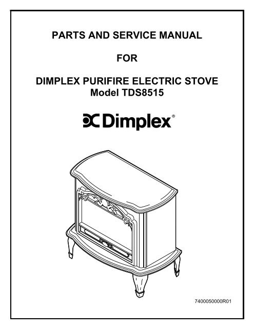
PARTS AND SERVICE MANUAL<br />
FOR<br />
DIMPLEX PURIFIRE ELECTRIC STOVE<br />
Model TDS8515<br />
7400050000R01
Table of Contents<br />
OPERATION ............................................................................................................................. 2<br />
WIRING DIAGRAM ................................................................................................................... 5<br />
REPLACEMENT PARTS ........................................................................................................... 7<br />
UPPER LIGHT BULB REPLACEMENT ..................................................................................... 8<br />
LOWER LIGHT BULB REPLACEMENT .................................................................................... 9<br />
TO REPLACE THE FILTER .................................................................................................... 10<br />
TO REPLACE MAIN POWER, MANUAL SELECTION, AND LIGHT SWITCHES .................. 11<br />
TO REPLACE THE HEATER ASSEMBLY .............................................................................. 12<br />
TO REPLACE THE CIRCUIT BOARD..................................................................................... 13<br />
TO REPLACE FLAME MOTOR/FLAME ROD ......................................................................... 14<br />
TO REPLACE THE POWER CORD ........................................................................................ 15<br />
TO REPLACE THE THERMOSTAT ........................................................................................ 16<br />
TROUBLESHOOTING<br />
GUIDE ................................................................................................ 17<br />
1
OPERATION<br />
To access the controls, go to the back of the stove.<br />
A. MAIN POWER ON/OFF SWITCH<br />
The main on/off switch supplies power to all unit<br />
A<br />
functions (flame, purifire, heater).<br />
B<br />
B. MANUAL SELECTION SWITCH<br />
To choose between flame effect setting, flame<br />
C<br />
effect with Purifire setting, and flame effect with<br />
Purifire and heat setting.<br />
C. INTERIOR LIGHT ON/OFF SWITCH<br />
The interior light on/off switch supplies power to<br />
the interior light.<br />
D. HEATER THERMOSTAT CONTROL<br />
To adjust the temperature to your individual<br />
requirements, turn the thermostat control<br />
clockwise all the way to turn on the heater.<br />
When the room reaches the desired temperature,<br />
D<br />
turn the thermostat knob counter clockwise until<br />
you hear a click. Leave in this position to maintain<br />
the room temperature at this setting. For additional<br />
heat, turn clockwise until you hear the click again<br />
and the heater will turn on.<br />
RESETTING THE TEMPERATURE CUTOFF SWITCH<br />
Should the heater overheat, an automatic cut out will turn the heater off and it will not come<br />
back on without being reset. It can be reset by switching the MAIN ON/OFF SWITCH to OFF<br />
and waiting 5 minutes before switching the unit back on.<br />
CAUTION<br />
If you need to continuously reset the heater, unplug the unit and call <strong>Dimplex</strong> technical support<br />
at 1-888-DIMPLEX (1-888-346-7539) Extension 4.<br />
NOTE<br />
The heater may emit a slight, harmless odor when first used. This odor is a normal condition<br />
caused by initial heating of internal heater parts and will not occur again.<br />
2
REMOTE CONTROL USAGE<br />
This stove is supplied with a radio frequency remote control. This remote control has a range<br />
of approximately 50 feet (15.25m); it does not have to be pointed at the fireplace and can pass<br />
through most obstacles (including walls). It is supplied with one of 243 independent<br />
frequencies to prevent interference with other units. The frequency code is indicated on the<br />
back of the transmitter.<br />
FIGURE 2<br />
FIGURE 3<br />
Frequency<br />
Code<br />
Main<br />
Power<br />
Switch<br />
<strong>Manual</strong><br />
Selection<br />
Switch<br />
Interior<br />
Light<br />
Switch<br />
A. Remote Control Initialization<br />
This procedure is required every time there is a loss<br />
of power to the remote control in the fireplace.<br />
(I.e. power failure, breaker tripped, main power switch<br />
is turned off)<br />
1. Ensure that power is supplied through main<br />
service panel.<br />
2. Locate manual controls. (refer to FIGURE 3)<br />
3. Activate main power switch, (“ ” position) red<br />
indicator light 1 will flash.<br />
4. Press and hold the manual selection switch for five<br />
seconds (“ ” position) UNTIL the second red<br />
indictor light flashes.<br />
5. Press ON button located on the remote control<br />
transmitter (FIGURE 2). This will synchronize the<br />
remote control transmitter and receiver.<br />
B. Remote Control Usage<br />
The remote control operates the fireplace levels<br />
sequentially. The level is increased every time the<br />
ON button on the transmitter is pressed. The<br />
fireplace can be turned off at any point by pressing<br />
the OFF button on the remote control transmitter.<br />
Level 1: The flame effect is turned on and the first red<br />
indicator light is activated.<br />
Level 2: The flame effect remains on, the Purifire<br />
is activated, and the first and second red<br />
indicator lights are activated.<br />
Level 3: The flame effect and Purifire remain on,<br />
the heater is activated, and all three red<br />
indicator lights are activated.<br />
3<br />
FIGURE 4<br />
Level 1 Indicator<br />
Level 2 Indicator<br />
Level 3 Indicator
MANUAL SELECTION SWITCH<br />
Operates the electric fireplace in the same manner as the remote control transmitter. Pressing<br />
the switch up (“ I ” position) has the same effect as the ON button on the remote control and<br />
pressing the switch down (“ II ” position) has the same effect as the OFF button of the remote<br />
control. Pressing the switch up once activates Level 1, twice activates Level 2, and three<br />
times activates Level 3. Pressing the switch down turns the electric fireplace OFF.<br />
Level 1: The flame effect is turned on and the first red indicator light flashes momentarily.<br />
Level 2: The flame effect remains on, the heater is activated to the low heat setting, and the<br />
first and second red indicator lights flash momentarily.<br />
Level 3: The flame effect remains on, the heater is set to the high heat setting, and all three<br />
red indicators flash momentarily.<br />
4
WIRING DIAGRAM<br />
5
TDS8515<br />
1<br />
13<br />
6<br />
18<br />
4<br />
17<br />
11<br />
12<br />
6<br />
10<br />
14<br />
2<br />
15<br />
3<br />
16<br />
5<br />
7<br />
8<br />
9
TDS8515<br />
REPLACEMENT PARTS<br />
STOVE, ELECTRIC 23", PURIFIRE<br />
CATALOGUE NO. TDS8515<br />
PART NO. 69004712**<br />
MADE IN: CHINA<br />
REPLACEMENT PART REPLACEMENT PART NO.<br />
1. LOG SET 0438200200RP<br />
2. FOOT 0438210104RP<br />
3. FLAME MOTOR 2000210100RP<br />
4. HEATER ASSEMBLY 2000230100RP<br />
5. THERMOSTAT 2300150100RP<br />
6. LOWER LIGHT HARNESS 2500280100RP<br />
7. ON/OFF SWITCH 2800070500RP<br />
8. HEATER ON/OFF SWITCH 2800070200RP<br />
9. UPPER LIGHT ON/OFF SWITCH 2800070200RP<br />
10. CORD SET 4100040300RP<br />
11. UPPER LIGHT HARNESS 4200120400RP<br />
12. MIRROR 5900060600RP<br />
13. REFLECTOR ASSEMBLY 5900080600RP<br />
14. FILTER 0439060100RP<br />
15. TERMINAL BLOCK 4000070100RP<br />
16. KNOB CONTROL 8800000300RP<br />
17. REMOTE TRANSMITTER 3000370600RP<br />
18. REMOTE RECEIVER (3-STAGE) Mod 0 - C 3000431100RP<br />
Mod D 3000820600RP<br />
** = Colour code<br />
7
TDS8515<br />
If unit was operating prior to servicing allow at least 10 minutes for light bulbs and<br />
heating element to cool off to avoid accidental burning of skin.<br />
Disconnect power before attempting any maintenance or cleaning to reduce the risk of<br />
electric shock or damage to persons.<br />
Light bulbs need to be replaced when you notice a dark section of the flame. There are<br />
four bulbs under the log set which generate the flames and embers.<br />
It is a good idea to replace all of the light bulbs at one time if they are close to the end of<br />
their rated life. Group replacement will reduce the number of times you need to open<br />
the unit to replace the light bulbs.<br />
UPPER LIGHT BULB REPLACEMENT<br />
1. Remove the 2 screws at the upper corners of the back panel.<br />
2. Lift the back end of the top to clear the brackets and pull back. Lift top carefully and<br />
place to the side of the stove.<br />
3. Caution should be taken as the top mounting brackets may scratch the finish.<br />
4. Hold the socket while unscrewing the bulb.<br />
5. Hold the socket while screwing in the new bulb.<br />
6. Re-install the top of the stove.<br />
LIGHT BULB REQUIREMENTS<br />
Quantity of 1 clear chandelier or candelabra bulbs with an E-12 (small) socket base,<br />
15 watt rating.<br />
8
TDS8515<br />
If unit was operating prior to servicing allow at least 10 minutes for light bulbs and<br />
heating element to cool off to avoid accidental burning of skin.<br />
Disconnect power before attempting any maintenance or cleaning to reduce the risk of<br />
electric shock or damage to persons.<br />
Light bulbs need to be replaced when you notice a dark section of the flame. There are<br />
four bulbs under the log set which generate the flames and embers.<br />
It is a good idea to replace all of the light bulbs at one time if they are close to the end of<br />
their rated life. Group replacement will reduce the number of times you need to open<br />
the unit to replace the light bulbs.<br />
LOWER LIGHT BULB REPLACEMENT<br />
1. Gently place stove on its back on a flat surface.<br />
2. Remove the thermostat knob.<br />
3. Remove the heater cover retaining screws located on the bottom of the stove and<br />
lower heater/light assembly onto the floor.<br />
4. Remove the burnt out bulbs by pulling straight out of the socket. If bulbs are difficult<br />
to remove from socket, move bulb from side to side while pulling, being careful not to<br />
damage the light socket.<br />
5. Replace lower light bulbs<br />
6. Caution should be taken not to touch the glass portion of the new halogen bulbs.<br />
Doing so may lead to shorter bulb life.<br />
7. Reassemble in the reverse order as above.<br />
LIGHT BULB REQUIREMENTS<br />
Quantity of 3 -35 watt Halogen Quartz lamps, 120 volt, G9 base<br />
9
TDS8515<br />
If unit was operating prior to servicing allow at least 10 minutes for light bulbs and<br />
heating element to cool off to avoid accidental burning of skin.<br />
Disconnect power before attempting any maintenance or cleaning to reduce the risk of<br />
electric shock or damage to persons.<br />
TO REPLACE THE FILTER<br />
1. Remove the 2 screws at the upper corners of the back panel.<br />
2. Lift the back end of the top to clear the brackets and pull back. Lift top carefully<br />
and place to the side of the stove.<br />
3. Caution should be taken as the top mounting brackets may scratch the finish.<br />
4. Remove the old filter and replace with new filter.<br />
5. Reassemble in the reverse order as above.<br />
10
TDS8515<br />
If unit was operating prior to servicing allow at least 10 minutes for light bulbs and<br />
heating element to cool off to avoid accidental burning of skin.<br />
Disconnect power before attempting any maintenance or cleaning to reduce the risk of<br />
electric shock or damage to persons.<br />
Light bulbs need to be replaced when you notice a dark section of the flame. There are<br />
four bulbs under the log set which generate the flames and embers.<br />
It is a good idea to replace all of the light bulbs at one time if they are close to the end of<br />
their rated life. Group replacement will reduce the number of times you need to open<br />
the unit to replace the light bulbs.<br />
TO REPLACE MAIN POWER, MANUAL SELECTION,<br />
AND LIGHT SWITCHES<br />
1. Remove the 2 screws at the upper corners of the back panel.<br />
2. Lift the back end of the top to clear the brackets and pull back. Lift top carefully and<br />
place to the side of the stove.<br />
3. Caution should be taken as the top mounting brackets may scratch the finish.<br />
4. Locate the switch to be replaced.<br />
5. Remove the wiring clips and connection noting their original locations<br />
6. Depress the retainer clips on the rear of the switch and push the switch out of the<br />
rear of the stove.<br />
7. Re-install the top of the stove.<br />
11
TDS8515<br />
If unit was operating prior to servicing allow at least 10 minutes for light bulbs and<br />
heating<br />
element to cool off to avoid accidental burning of skin.<br />
Disconnect power before attempting any<br />
maintenance or cleaning to reduce the risk of<br />
electric<br />
shock or damage to persons.<br />
TO<br />
REPLACE THE HEATER ASSEMBLY<br />
1. Gently place stove on its back on a flat surface.<br />
2. Remove the thermostat knob.<br />
3. Remove the heater cover retaining screws located on the bottom of the stove and<br />
lower heater/light assembly onto the floor.<br />
4. Remove the reflector rod and motor assembly by removing the screws on the front<br />
and rear of the heater cover.<br />
5. Remove the heater retaining screws form the bottom of the heater cover.<br />
6. Disconnect the wiring clips and connections noting their original locations.<br />
7.<br />
Reassemble in the reverse order as above.<br />
12
TDS8515<br />
If unit was operating prior to servicing allow at least 10 minutes for light bulbs and<br />
heating<br />
element to cool off to avoid accidental burning of skin.<br />
Disconnect power before attempting any<br />
maintenance or cleaning to reduce the risk of<br />
electric<br />
shock or damage to persons.<br />
TO<br />
REPLACE THE CIRCUIT BOARD<br />
1. Gently place stove on its back on a flat surface.<br />
2. Remove the thermostat knob.<br />
3. Remove the heater cover retaining screws located on the bottom of the stove and<br />
lower heater/light assembly onto the floor.<br />
4. Remove the reflector rod and motor assembly by removing the screws on the front<br />
and rear of the heater cover.<br />
5. Disconnect the wiring<br />
clips and connections from the circuit board, noting their<br />
original locations.<br />
6. From inside the fireplace, break off the six mounting studs on the circuit board<br />
by<br />
grasping with pliers and twisting on the protruding part<br />
of the stud, push the<br />
remainder of the studs out through the top panel.<br />
7. NOTE: New mounting studs are supplied with the replacement circuit board.<br />
8. Properly orient the new circuit board and connect all of the wiring connections<br />
13
TDS8515<br />
If unit was operating prior to servicing allow at least 10 minutes for light bulbs and<br />
heating<br />
element to cool off to avoid accidental burning of skin.<br />
Disconnect power before attempting any<br />
maintenance or cleaning to reduce the risk of<br />
electric shock or damage to persons.<br />
TO REPLACE FLAME MOTOR/FLAME ROD<br />
1. Gently place stove on its back on a flat surface.<br />
2. Remove the thermostat knob.<br />
3. Remove the heater cover retaining screws located on the bottom of the stove and<br />
lower heater/light assembly onto the floor.<br />
4. Remove the reflector rod from the flame motor<br />
by pulling the end of the rod to the<br />
left and separating it from the rubber sleeve.<br />
5. Remove the rubber sleeve from the motor shaft.<br />
6. Remove the 2 motor mounting screws and remove the flame motor.<br />
7. Discard the old flame motor.<br />
8. Lay the stove on its back with the front window facing upward.<br />
9. Remove the bottom heater assembly<br />
cover being careful not to damage any of the<br />
wiring and lay it on the floor.<br />
10. Loosen the flame motor connections<br />
on the terminal block and remove the wires<br />
noting their original locations.<br />
11.<br />
Reassemble in the reverse order.<br />
14
TDS8515<br />
If unit was operating prior to servicing allow at least 10 minutes for light bulbs and<br />
heating<br />
element to cool off to avoid accidental burning of skin.<br />
Disconnect power before attempting any<br />
maintenance or cleaning to reduce the risk of<br />
electric<br />
shock or damage to persons.<br />
TO<br />
REPLACE THE POWER CORD<br />
1. Gently place stove on its back on a flat surface.<br />
2. Remove the thermostat knob.<br />
3. Remove the heater cover retaining screws located on the bottom of the stove and<br />
lower heater/light assembly onto the floor.<br />
4. Remove the reflector rod and motor assembly by removing the screws on the front<br />
and rear of the heater cover.<br />
5. Located and disconnect the power cord wiring<br />
connections from the heater and Main<br />
on/off switch noting their original locations.<br />
6. With needle nose pliers grasp the power cord strain<br />
relief grommet from inside the<br />
rear panel and push while twisting to remove.<br />
7. Pull the power cord out through the hole in the rear cover.<br />
8. Install the new cord set through the hole in the rear cover by placing the strain<br />
relief<br />
over the cord, hold the strain relief with pliers and slide into mounting<br />
hole.<br />
9. Connect all of the wiring connections in their<br />
original locations.<br />
10. Reassemble in the reverse order as above.<br />
15
TDS8515<br />
If unit was operating prior to servicing allow at least 10 minutes for light bulbs and<br />
heating<br />
element to cool off to avoid accidental burning of skin.<br />
Disconnect power before attempting any<br />
maintenance or cleaning to reduce the risk of<br />
electric<br />
shock or damage to persons.<br />
TO<br />
REPLACE THE THERMOSTAT<br />
1. Gently place stove on its back on a flat surface.<br />
2. Remove the thermostat knob.<br />
3. Remove the heater cover retaining screws located on the bottom of the stove and<br />
lower heater/light assembly onto the floor.<br />
4. Remove the reflector rod and motor assembly by removing the screws on the front<br />
and rear of the heater cover.<br />
5. Disconnect the wiring clips from the thermostat.<br />
6. Remove the 2 thermostat mounting screws and remove the thermostat.<br />
7. Connect all of the wiring connections to the new<br />
thermostat.<br />
8.<br />
Reassemble in the reverse order as above.<br />
16
TDS8515<br />
TROUBLESHOOTING GUIDE<br />
GENERAL<br />
Problem Cause Solution<br />
Circuit breaker trips<br />
o r fuse blows when<br />
unit is turned on<br />
Unit turns<br />
on or off<br />
by itself<br />
Lights dim in room<br />
while the unit is on<br />
Power cord gets<br />
warm<br />
APPEARANCE<br />
Improper circuit current rating<br />
Remote control has a similar<br />
frequency to other remotes in<br />
the area<br />
Radio frequency disturbance<br />
from outside sources<br />
Unit is d rawing close to circuit<br />
current rating<br />
17<br />
Additional appliances may<br />
exceed the current rating of<br />
the circuit breaker or fuse.<br />
Plug unit into another outlet<br />
or install unit on a dedicated<br />
15 amp circuit<br />
Replace hand held<br />
remote<br />
control<br />
Move the unit to another<br />
outlet or install unit on a<br />
dedicated 15 amp circuit<br />
The power cord may get<br />
<strong>Service</strong> <strong>Manual</strong><br />
Reference<br />
Normal operation sl ightly warm to the touch<br />
when the heater is on<br />
Defective power cord Replace power cord Page 15<br />
Problem Cause Solution<br />
Fireplace does not<br />
turn on<br />
Flame frozen<br />
Flame not bright or<br />
flame not visible<br />
Log set dim, ember<br />
bed not glowing<br />
Improper operation Refer to User’s Guide<br />
<strong>Service</strong> <strong>Manual</strong><br />
Reference<br />
Defective main on/off switch Replace main on/off switch Page 11<br />
Defective optional remote Install new battery into the<br />
control<br />
handheld transmitter<br />
Page 3<br />
Loose wiring Check wiring connections Page 5<br />
Defective flame motor Replace flame motor Page 14<br />
Loose wiring Check wiring connections Page 5<br />
Burnt light bulbs Replace light bulbs Pages 8-9<br />
Loose wiring Check wiring connections Page<br />
5<br />
Defective light harness Replace light harness<br />
Burnt light bulbs Replace light bulbs Pages 8-9<br />
Flame Shutter Defective flame motor Replace flame motor Page 14
TDS8515<br />
TROUBLESHOOTING GUIDE<br />
HEATER<br />
Defective thermostat Replace thermostat<br />
<strong>Service</strong> <strong>Manual</strong><br />
Reference<br />
Page 16<br />
Problem Cause Solution<br />
Heater is not<br />
turning off<br />
Heater is not<br />
turning on<br />
Heater emits an<br />
odour<br />
Heater fan turns on<br />
but heater lacks<br />
heat<br />
Heating element is<br />
glowing red<br />
Improper operation See Operation Section Page 2<br />
Loose wiring Trace wiring in unit Page 5<br />
Defective Circuit Board Replace Circuit Board Page 13<br />
Defective thermostat Replace thermostat Page 16<br />
Defective heater assembly Replace heater assembly Page 12<br />
Improper operation See Operation Section Page 2<br />
Loose wiring Trace wiring in unit Page 5<br />
Defective Circuit Board Replace Circuit Board Page 13<br />
Normal operation<br />
18<br />
Normal operation is when<br />
the heater emits an odour for<br />
a brief period after the<br />
heater is initially turned on.<br />
The heater is burning off any<br />
dust accumulated during<br />
manufacturing or operation.<br />
Defective heater assembly Replace heater assembly Page 12<br />
Loose wiring Trace wiring in unit Page 5<br />
Improper operation See Operation Section Page 2<br />
Defective thermostat Replace thermostat Page 16<br />
Loose wiring Trace wiring in unit Page 5<br />
Defective heater assembly Replace heater assembly<br />
Small glowing sections of<br />
Page 12<br />
Normal operation<br />
the element are considered<br />
normal.<br />
If larger glowing sections are<br />
causing the heater to trip the<br />
Defective heater assembly thermal cut out, unplug unit,<br />
discontinue use and replace<br />
heater assembly<br />
Page 12
TDS8515<br />
TROUBLESHOOTING GUIDE<br />
HEATER (CONTINUED)<br />
Problem Cause Solution<br />
<strong>Service</strong> <strong>Manual</strong><br />
Reference<br />
Build up of dirt in heater Vacuum/Clean Heater<br />
Heater Turns Off assembly<br />
Assembly<br />
after a few minutes<br />
of operation but<br />
Build up of dirt in Purifire<br />
Filter<br />
Clean/Replace Filter Page 10<br />
flame stays On<br />
Defective Heater Assembly Replace Heater Assembly Page 12<br />
Heater fan runs<br />
continuously<br />
NOISE<br />
Loose wiring Trace wiring in unit Page 5<br />
Defective heater on/off switch Replace heater on/off switch Page 11<br />
Defective heater assembly Replace heater assembly Page 12<br />
Problem Cause Solution<br />
Excessive noise<br />
with the heater on<br />
Grinding or<br />
excessive noise<br />
with the heater off<br />
Dirty blower assembly Clean blower assembly<br />
19<br />
<strong>Service</strong> <strong>Manual</strong><br />
Reference<br />
Defective blower assembly Replace heater assembly Page 12<br />
Moving flame rod hitting or<br />
rubbing against internal<br />
components<br />
Flame rod replacement Page 14<br />
Defective flame motor Replace flame motor Page 14
1367 Industrial Road Cambridge ON Canada N1R 7G8<br />
1-888-346-7539 www.dimplex.com<br />
In keeping with our policy of continuous product improvement, we reserve the right to make changes without notice.<br />
© 2011 <strong>Dimplex</strong> North America Limited<br />
20