Bulletin 1728F-804: Specifications and Drawings for 12.47/7.2 kV ...
Bulletin 1728F-804: Specifications and Drawings for 12.47/7.2 kV ...
Bulletin 1728F-804: Specifications and Drawings for 12.47/7.2 kV ...

Create successful ePaper yourself
Turn your PDF publications into a flip-book with our unique Google optimized e-Paper software.
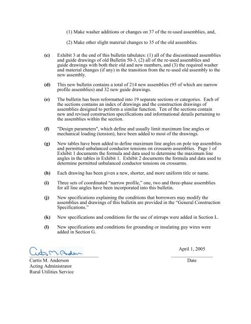
(1) Make washer additions or changes on 37 of the re-used assemblies, <strong>and</strong>,<br />
(2) Make other slight material changes to 35 of the old assemblies.<br />
(c) Exhibit 3 at the end of this bulletin tabulates: (1) all of the discontinued assemblies<br />
<strong>and</strong> guide drawings of old <strong>Bulletin</strong> 50-3, (2) all of the re-used assemblies <strong>and</strong><br />
guide drawings with both their old <strong>and</strong> new numbers, <strong>and</strong> (3) the required washer<br />
<strong>and</strong> material changes (if any) in the transition from the re-used old assembly to the<br />
new assembly.<br />
(d) This new bulletin contains a total of 214 new assemblies (95 of which are narrow<br />
profile assemblies) <strong>and</strong> 32 new guide drawings.<br />
(e) The bulletin has been re<strong>for</strong>matted into 19 separate sections or categories. Each of<br />
the sections contains an index of drawings <strong>and</strong> the construction drawings of<br />
assemblies designed to per<strong>for</strong>m a similar function. Ten of the sections contain<br />
new <strong>and</strong> revised construction specifications <strong>and</strong> in<strong>for</strong>mational details pertaining to<br />
the assemblies within the section.<br />
(f) "Design parameters", which define <strong>and</strong> usually limit maximum line angles or<br />
mechanical loading (tension), have been added to most of the drawings.<br />
(g) New tables have been added to define maximum line angles on pole top assemblies<br />
<strong>and</strong> permitted unbalanced conductor tensions on crossarm assemblies. Page 1 of<br />
Exhibit 1 documents the <strong>for</strong>mula <strong>and</strong> data used to determine the maximum line<br />
angles in the tables in Exhibit 1. Exhibit 2 documents the <strong>for</strong>mula <strong>and</strong> data used to<br />
determine permitted unbalanced conductor tensions on crossarms.<br />
(h) Each drawing has been given a new, shorter, <strong>and</strong> more uni<strong>for</strong>m title or name.<br />
(i) Three sets of coordinated “narrow profile,” one, two <strong>and</strong> three-phase assemblies<br />
<strong>for</strong> all line angles have been incorporated into this bulletin.<br />
(j) New specifications explaining the conditions that borrowers may modify the<br />
assemblies <strong>and</strong> drawings of this bulletin are provided in the “General Construction<br />
<strong>Specifications</strong>.”<br />
(k) New specifications <strong>and</strong> conditions <strong>for</strong> the use of stirrups were added in Section L.<br />
(l) New specifications <strong>and</strong> conditions <strong>for</strong> grounding or insulating guy wires were<br />
added in Section G.<br />
April 1, 2005<br />
____________________________ _________________<br />
Curtis M. Anderson Date<br />
Acting Administrator<br />
Rural Utilities Service