L:\Standard Specifications and Drawings\Drawings ... - City of Fresno
L:\Standard Specifications and Drawings\Drawings ... - City of Fresno
L:\Standard Specifications and Drawings\Drawings ... - City of Fresno

Create successful ePaper yourself
Turn your PDF publications into a flip-book with our unique Google optimized e-Paper software.
TABLE OF CONTENTS<br />
PUBLIC WORKS STANDARD DRAWINGS<br />
NO. TITLE OF DRAWING<br />
P-1 Residential Driveway Approaches for 14’-12’10’-8’ Pattern <strong>and</strong> for 5’ Combination<br />
P-2 Commercial Driveway Approaches for 14’-12’10’-8’ Pattern <strong>and</strong> for 5’ Combination<br />
P-3 Driveway Approaches for Various Curb Patterns<br />
P-4 Local Street Driveway Approaches for Monolithic Sidewalk<br />
P-5 Construction Details for Concrete Sidewalk, Curb <strong>and</strong> Gutter<br />
P-6 Driveway Opening <strong>and</strong> Clearance Requirements<br />
P-7 Curvilinear Sidewalk<br />
P-8 Tree Well Design<br />
P-9 Concrete Construction Details<br />
P-10 Concrete Valley Gutter<br />
P-11 Special Valley Gutter (Cross Drain Replacement)<br />
P-12 Alley Cross-Section & Plan (Residential – Commercial)<br />
P-13 Concrete Alley Approach<br />
P-14 24’ Alternative Alley with Wedged Curb<br />
P-15 Alley Traffic Calming Pinch Point<br />
P-16 Curb Removal<br />
P-17 St<strong>and</strong>ard Drawing Sizes<br />
P-18 St<strong>and</strong>ard Cul-De-Sac<br />
P-19 St<strong>and</strong>ard Cul-De-Sac for Local Industrial Streets<br />
P-20 No Longer Used<br />
P-21 Parking Lot Paving Detail<br />
P-22 Lot Drainage Detail<br />
P-23 Sidewalk Drains<br />
P-24 Street Intersection Typical Curb Returns, L<strong>and</strong>ings, <strong>and</strong> Right <strong>of</strong> Way<br />
P-25 Street Intersection Typical Curb Returns, L<strong>and</strong>ings, <strong>and</strong> Right <strong>of</strong> Way<br />
P-26 Street Intersection Typical Curb Returns, L<strong>and</strong>ings, <strong>and</strong> Right <strong>of</strong> Way<br />
P-27 Street Intersection Typical Curb Returns, L<strong>and</strong>ings, <strong>and</strong> Right <strong>of</strong> Way<br />
P-28 Diagonal Curb Ramp (Use Only When Necessary)<br />
P-29 Modified Curb Ramp (at Street Type Driveway Approach)<br />
P-30 Dual Curb Ramps Major Street Intersection<br />
P-31 Modified Curb Ramp<br />
P-32 Detectable Warning Devices<br />
P-33 Typical Refuse Container Enclosure Details<br />
P-34 Typical Refuse Container Enclosure Details<br />
P-35 Trash Enclosed Gate Details<br />
P-36 Property Monument Details<br />
P-37 Witness Corner<br />
P-38 Witness Corner Details<br />
P-39 No longer Used<br />
P-40 Benchmark Details<br />
P-41 Location <strong>of</strong> Underground Facilities<br />
P-42 Location <strong>of</strong> Underground Facilities for Arterial <strong>and</strong> Collector Streets
P-43 Trench Detail CATV for Local <strong>and</strong> Major Streets<br />
P-44 No Longer Used<br />
P-45 No Longer Used<br />
P-46 No Longer Used<br />
P-47 Minimum Traveled Way Formula<br />
P-48 Trench Backfill <strong>and</strong> Surface Replacement<br />
P-49 No Longer Used<br />
P-50 Street Construction Requirements <strong>and</strong> Traffic Devices<br />
P-51 Expressway <strong>and</strong> Super Arterial Cross-Section<br />
P-52 Arterial Street Cross-Section<br />
P-53 Collector Street Cross-Section (4 travel lanes)<br />
P-54 Collector Street Cross-Section (2 travel lanes)<br />
P-55 Industrial Street Cross-Sections<br />
P-56 Local Street Cross-Sections<br />
P-57 82’ Row Local Boulevard<br />
P-58 Asphalt Multi-Purpose Trail<br />
P-59 Concrete Multi-Purpose Trail<br />
P-60 Trail Details<br />
P-61 Trail-Street Intersection Typical Plan<br />
P-62 Median Isl<strong>and</strong> Left Turn Pockets (1 <strong>of</strong> 2)<br />
P-63 Median Isl<strong>and</strong> Left Turn Pockets (2 <strong>of</strong> 2)<br />
P-64 Median Isl<strong>and</strong> Parabolic Nose<br />
P-65 Bulb Design Frontage Road Terminations<br />
P-66 U-Turn Minimum Clearance<br />
P-67 Fire Access Lane Across Parkway<br />
P-68 Median Opening for Emergency Vehicles<br />
P-69 Street Intersection Detail<br />
P-70 Street Intersection detail with Dual Left Turn Lanes<br />
P-71 No Longer Used<br />
P-72 Fax Passenger Shelter Detail<br />
P-73 Bus Bays<br />
P-74 Expressway Barrier Fencing<br />
P-75 Expressway Barrier Fence Location<br />
P-76 Street Type Approach for Undivided Driveway<br />
P-77 Street Type Approach for Divided Driveway<br />
P-78 Major Street Connections for Local Streets <strong>and</strong> Street Type Approaches<br />
P-79 Typical Bike Lane Cross Sections<br />
P-80 Bike Lane Signs <strong>and</strong> Markings<br />
P-81 No Longer Used<br />
P-82 High Visibility Crosswalk<br />
P-83 Residential Traffic Circle for Four-Way Intersection<br />
P-84 Residential Traffic Circle (Case No.1)<br />
P-85 Residential Traffic Circle (Case No.2)<br />
P-86 Residential Entry Treatment<br />
P-87 No Longer Used<br />
P-88 Sign Post Detail<br />
P-89 Street Name Sign Placement<br />
P-90 Oversized Street Name Sign<br />
P-91 No Stopping Any Time Sign
P-92 Local Street Name Sign<br />
P-93 6” Concrete Masonry Wall with or Without 8” Soil Retention<br />
P-94 6” Concrete Masonry Wall Without Soil Retention<br />
P-95 6” Concrete Masonry Wall with 8” Max Soil Retention<br />
P-96 6” Concrete Masonry Wall St<strong>and</strong>ard Details<br />
P-97 Temporary Ponding Basin<br />
P-98 Chain Link Fence Construction Details<br />
P-99 Access Ramp Gate<br />
P-100 Temporary Timber Barricade
WATER STANDARD DRAWINGS<br />
NO. TITLE OF DRAWING<br />
W-1 1 ½” & 2” Service Connection & Meter Box Installation<br />
W-2 1” Service Connection & Meter Box Installation<br />
W-3 Fire Hydrant Installation<br />
W-4 Fire Hydrant Installation Valve Operator Detail<br />
W-5 Typical Fire Hydrant Marker Locations<br />
W-6 Thrust Block for Dead End Water Main<br />
W-7 Valve Lid & Paving Ring with Galvanized Casing<br />
W-8 Installation Procedure for Paving Ring & Lid<br />
W-9 Blow-Off Assembly Type A<br />
W-10 Blow-Off Assembly Type B<br />
W-11 Reduced Pressure Principle Backflow Assembly Installation<br />
W-12 Double Check Valve Installation<br />
W-13 Automatic Air Release <strong>and</strong> Vacuum Valve<br />
W-14 Pressure Vacuum Breaker Backflow Preventer Installation<br />
W-15 Typical Enclosure for Backflow Prevention Devices<br />
W-16 Fire Service Detector Check Installation<br />
W-17 Detector Bypass Meter Details<br />
W-18 Detector Check Requirements Related to Fire Service Improvements Greater Than 2”<br />
W-19 Installation Requirements for an Approved Air Gap Separation<br />
W-20 Approved Alternative Installation Requirements for an Air Gap System<br />
W-21 Approved Portable Water Transport Backflow Protection<br />
W-22 Guard Post Details<br />
W-23 Fire Hydrant Installation with Guard Posts<br />
W-24 Installation <strong>of</strong> Water Pipe in Jacked Steel Casing<br />
W-25 Valve Anchor for Line Valve<br />
W-26 Alternative to Full Concrete Encasement<br />
W-27 Typical Intersection Connection<br />
W-28 Service Casing<br />
W-29 Water Main Bedding Details<br />
W-30 Monitoring Well Manhole Construction Detail<br />
W-31 PVC Tee Restraints<br />
W-32 PVC Bend Restraints<br />
W-33 PVC Pipe Restraints<br />
W-34 Ductile Iron Tee Restraints<br />
W-35 Ductile Iron Bend Restraints<br />
W-36 Ductile Iron Pipe Restraints<br />
W-37 Hydrant Run Tee Restraints for PVC or Ductile Iron Pipe<br />
W-38 Concrete Vault <strong>and</strong> Cover Details<br />
W-39 Concrete Vault Knockout Details<br />
W-40 Compound Meter Setting with By-Pass<br />
W-41 Turbine Meter Setting with By-Pass<br />
W-42 Fire Service Meter Setting with By-Pass<br />
W-43 Temporary RP Principle Backflow Assembly Installation<br />
W-44 Sample Station Installation<br />
W-45 <strong>City</strong> <strong>of</strong> <strong>Fresno</strong> – water Division Well Destruction Requirements
SEWER STANDARD DRAWINGS<br />
NO. TITLE OF DRAWING<br />
S-1 House Branch & Utilities Locations in Street<br />
S-2 Special Sewer Manhole for Large Diameter Main<br />
S-3 48” Sewer Manhole with Precast Sections <strong>and</strong> Cast Iron Frame & Cover<br />
S-4 60” Sewer Manhole with Precast Sections <strong>and</strong> Cast Iron Frame & Cover<br />
S-5 Cast Iron Manhole Frame & Cover<br />
S-6 Sloping Lamphole with C.I. Cleanout & Cover<br />
S-7 Installation <strong>of</strong> Sewer Pipe in Jacked Steel Casing<br />
S-8 House Branch Connections<br />
S-9 Additional Limitations on House Branch Connections<br />
S-10 Sewer Main Trench, Bedding, <strong>and</strong> Backfill Detail<br />
S-11 Drop Sewer Main Connections (6” <strong>and</strong> 8” only)
ELECTRICAL STANDARD DRAWINGS<br />
NO. TITLE OF DRAWING<br />
E-1 Streetlight-Major Street with Base, Pull Box & PVC Conduit<br />
E-2 Streetlight-Local Street with No Base, No Pull Box & PVC Conduit<br />
E-3 Streetlight-Local Street Overhead Service – Wood Pole<br />
E-4 Streetlights/Traffic Signals Concrete Pull Boxes<br />
E-5 Streetlight-Connection Diagram<br />
E-6 Streetlight Layout<br />
E-7 Streetlight-Placement Divided Arterial Streets<br />
E-8 Streetlight-Placement Collector Street<br />
E-9 Streetlight-Placement Local Streets<br />
E-10 Streetlight-Placement Expressway<br />
E-11 Streetlight-Placement Cul-De-Sac Streets<br />
E-12 Streetlight-Restrictions Cul-De-Sac Designs<br />
E-13 Signal Lights PVC Encased Loop Detectors<br />
E-14 Signal Lights Loop Detector Placement<br />
E-15 Signal Light Wiring New Installations 26-100 Cabinets<br />
E-16 Signal Light Wiring Retr<strong>of</strong>it <strong>of</strong> Existing 21-100 Cabinets<br />
E-17 Signal Light Service Foundation Detail<br />
E-18 Streetlight Wiring<br />
E-19 Vehicle Signal Terminal Location<br />
E-20 Pedestrian Signal, & PPB Terminal Locations<br />
E-21 Streetlight Irrigation Service Installation<br />
E-22 Service Riser Detail from Existing Streetlight<br />
E-23 Signal Light Coordination Cable Termination<br />
E-24 Signal Light Equipment Placement Guideline<br />
E-24A Signal Lights/Dual Ramps Equipment Placement Guideline<br />
E-25 Streetlight/Safety Light Pole Numbering<br />
E-26 Streetlight Ornamental Pole Numbering<br />
E-27 Signal Light Foundation Wire-Way Detail<br />
E-28 Streetlight Point <strong>of</strong> Service Concrete Pull Box<br />
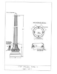
E-29 Downtown Signal & Streetlight Poles Decorative Pole Boundary<br />
E-30 Downtown Streetlight Decorative Pole Details<br />
E-31 Downtown Signal Poles Decorative Pole Details Type-1-A, 16. 17B<br />
E-32 Downtown Signal Poles Decorative Pole Details Type-19. 24<br />
E-33 Downtown Signal Poles Decorative Pole Details Type-26. 29<br />
E-34A Emergency Vehicle Preemption Opticom Connections 721 Detector <strong>and</strong> LT<br />
Count Loop Mod.<br />
E-34B 332L Cabinet / 2070L Detection C11S Cable Connections <strong>and</strong> Master/Signal CB<br />
E-35 Bus Shelter Lighting Connection Detail<br />
E-36 Flashing Beacon Wiring New Installations 26-100 Cabinets
INTELLIGENT TRANSPORTATION SYSTEM<br />
STANDARD DRAWINGS<br />
NO. TITLE OF DRAWING<br />
ITS-1 Typical ITS Corridor Layout<br />
ITS-2 Typical ITS Intersection Layout<br />
ITS-3 Typical ITS Intersection Conduit Run Layout<br />
ITS-3A Typical ITS Intersection Conduit Run Layout with Hub<br />
ITS-4 ITS Conduit Trench Detail No. 1<br />
ITS-5 ITS Conduit Trench Detail No. 2<br />
ITS-6 ITS Conduit Trench Layout No. 1<br />
ITS-7 ITS Conduit Trench Layout No. 2<br />
ITS-8 ITS Conduit Trench Layout No. 3<br />
ITS-9 ITS Conduit Trench Layout No. 4<br />
ITS-10 ITS Conduit Trench Layout No. 5<br />
ITS-11 ITS 3’ X 5’ Vault Details No. 1<br />
ITS-12 ITS 3’ X 5’ Vault Details No. 2<br />
ITS-13 ITS 4’ X 7’ Vault Details No. 1<br />
ITS-14 ITS 4’ X 7’ Vault Details No. 2<br />
ITS-15 Radar Detection Station Details No. 1<br />
ITS-16 Radar Detection Station Details No. 2<br />
ITS-17 Radar Detection Station Details No. 3<br />
ITS-18 IP Camera<br />
ITS-18A Traffic Signal Mounted IP Camera<br />
ITS-19 Tonable T-LOC Coupling<br />
ITS-20 Communication Cabinet Details<br />
ITS-20A Model 336 Communications Cabinet Details<br />
ITS-21 Communication Cabinet Wiring Diagram<br />
ITS-21A Model 336 Communication Cabinet Wiring Diagram<br />
ITS-21B Model 336 Communication Cabinet Equipment Assemblies<br />
ITS-22 Hub Foundation Grounding Details<br />
ITS-23 Hub Cabinet Foundation Detail<br />
ITS-24 Hub Cabinet Wiring Diagram<br />
ITS-25 ITS Hub Cabinet Details No. 2<br />
ITS-26 ITS Hub Cabinet Service Pedestal Schematic<br />
ITS-27A Wireless ITS Installation<br />
ITS-27B Wireless ITS Installation Details
ALTERNATE PUBLIC IMPROVEMENT DRAWINGS<br />
NO. TITLE OF DRAWING<br />
API-1 Modified Streets<br />
API-2 Modified Street Improvement St<strong>and</strong>ards<br />
API-3 Modified Street Improvement St<strong>and</strong>ards<br />
API-4 Details for Modified Streets<br />
API-5 Intersection Details for Modified Streets (Local <strong>and</strong> ½ mile Local)<br />
API-6 Van Ness Extension – Herndon Ave. to San Joaquin River Bluff<br />
API-7 Minnewawa Avenue – Fancher Creek to California Avenue<br />
API-8 Minnewawa Avenue – California Ave. to Butler Ave.<br />
API-9 Minnewawa Avenue – Butler Ave. to Tulare Ave.
SHEET SIZE LEFT BORDER OTHER BORDERS TITLE BLOCK<br />
A 11" X 8 1/2" .5 " .5 " A<br />
AA 11" X 17" .5 " .5 " A<br />
B 12" X 25 1/4" .25 " .25 " B<br />
C 12" X 36" 1 " .25 " B<br />
D ** 24" X 25 1/4" 1 " .25 " B<br />
E 24" X 36" 1 " .25 " B<br />
F 31" X 36" 1 " .25 " B<br />
G ** 31" X 25 1/4" 1 " .25 " B<br />
* 18" X 26" 1 " 1 "<br />
* ASSESSMENT DIAGRAMS, OFFICIAL PLAN LINES,<br />
TRACT MAPS AND PARCEL MAPS<br />
** NO LONGER USED BY THE CITY OF FRESNO
AREAS TO BE DRAINED FROM PRIVATE PROPERTY TO PUBLIC STREETS<br />
SURFACE TYPE OF DRAIN AREA<br />
AREA SURFACE REQUIRED<br />
2 ACRES PAVED 100 SQ. IN.<br />
200'X400' GRASS 25 SQ. IN.<br />
1.5 ACRES PAVED 75 SQ. IN.<br />
200'X300' GRASS 20 SQ. IN.<br />
1 ACRE PAVED 50 SQ. IN.<br />
200'X200' GRASS 12 SQ. IN.<br />
0.75 ACRE PAVED 40 SQ. IN.<br />
150'X200' GRASS 10 SQ. IN.<br />
0.5 ACRE PAVED 30 SQ. IN.<br />
100'X200' GRASS 6 SQ. IN.<br />
0.25 ACRE PAVED 16 SQ. IN.<br />
100'X100' GRASS 3 SQ. IN.<br />
USE 1 ACRE = 200'X200' OR 100'X400'<br />
AREA 3" DIA. PIPE = 7.1 SQ. IN.<br />
AREA 3"X 5" RECT. TUBE = 12.3 SQ. IN.<br />
AREA 3"X 6" RECT. TUBE = 14.9 SQ. IN.<br />
SIZE & NO. OF PIPES OR<br />
RECTANGULAR STEEL<br />
TUBE<br />
SIZE & NO. OF<br />
CHANNELS<br />
2-3"X6" RECT. TUBES 2-4"X14"<br />
1-3"PIPE & 1-3"X6" R.T. 2-3"X12"<br />
1-3"X5" RECT. TUBE 1-4"X14"<br />
3-3"X6" RECT. TUBE OR<br />
1-3"X5" RECT. TUBE<br />
2-3"X6" RECT. TUBE OR<br />
1-3"PIPE<br />
1-3"PIPE & 1-3"X5" R.T.<br />
1-3" PIPE<br />
AREA 4"X 14" CHANNEL = 56 SQ.IN.<br />
AREA 3"X 12" CHANNEL = 36 SQ.IN.<br />
1-4"X14"<br />
1-3"X12"
CURB RADIUS "A" DISTANCE<br />
30' 5'<br />
35' 7'<br />
40' 11'<br />
45' 15'<br />
50' 18'
CURVE TABLE<br />
DIST. FROM OFFSET<br />
POINT "A" B-B' = 11'<br />
0' 0.00'<br />
10' 0.17'<br />
20' 0.67'<br />
30' 1.50'<br />
40' 2.68'<br />
41.60' 2.90'<br />
50' 4.08'<br />
60' 5.48'<br />
70' 6.88'<br />
79.09' 8.15'<br />
80' 8.28'<br />
90' 9.47'<br />
100' 10.32'<br />
110' 10.83'<br />
120' 11.00'<br />
CURVE TABLE<br />
DIST. FROM OFFSET<br />
POINT "A" B-B' = 13'<br />
0' 0.00'<br />
10' 0.19'<br />
20' 0.77'<br />
30' 1.74'<br />
40' 3.08'<br />
43.12' 3.61'<br />
50' 4.77'<br />
60' 6.46'<br />
70' 8.16'<br />
77.71' 9.46'<br />
80' 9.96'<br />
90' 11.23'<br />
100' 12.21'<br />
110' 12.80'<br />
120' 13.00'<br />
CURVE TABLE<br />
DIST. FROM OFFSET<br />
POINT "A" B-B' = 16'<br />
0' 0.00'<br />
10' 0.23'<br />
20' 0.93'<br />
30' 2.09'<br />
40' 3.74'<br />
44.97' 4.73'<br />
50' 5.80'<br />
60' 7.93'<br />
70' 10.06'<br />
76.27' 11.40'<br />
80' 12.16'<br />
90' 13.85'<br />
100' 15.05'<br />
110' 15.76'<br />
120' 16.00'
CURVE TABLE<br />
DIST. FROM OFFSET<br />
POINT "A" B-B' = 14'<br />
0' 0.00'<br />
10' 0.21'<br />
20' 0.84'<br />
30' 1.89'<br />
40' 3.37'<br />
42.66' 3.84'<br />
50' 5.17'<br />
60' 6.98'<br />
70' 8.80'<br />
77.70' 10.19'<br />
80' 10.60'<br />
90' 12.09'<br />
100' 13.16'<br />
110' 13.79'<br />
120' 14.00'<br />
CURVE TABLE<br />
DIST. FROM OFFSET<br />
POINT "A" B-B' = 13'<br />
0' 0.00'<br />
10' 0.19'<br />
20' 0.77'<br />
30' 1.74'<br />
40' 3.11'<br />
43.12' 3.61'<br />
50' 4.77'<br />
60' 6.46'<br />
70' 8.16'<br />
77.71' 9.46'<br />
80' 9.83'<br />
90' 11.22'<br />
100' 12.21'<br />
110' 12.80'<br />
120' 13.00'<br />
CURVE TABLE<br />
DIST. FROM OFFSET<br />
POINT "A" B-B' = 16'<br />
0' 0.00'<br />
10' 0.23'<br />
20' 0.93'<br />
30' 2.09'<br />
40' 3.74'<br />
45.00' 4.74'<br />
50' 5.80'<br />
60' 7.93'<br />
70' 10.06'<br />
76.25' 11.39'<br />
80' 12.16'<br />
90' 13.85'<br />
100' 15.05'<br />
110' 15.76'<br />
120' 16.00'
CURVE TABLE<br />
DIST. FROM OFFSET<br />
POINT "A" B-B'<br />
10' 0.40'<br />
20' 1.58'<br />
30' 3.56'<br />
40' 6.33'<br />
50' 9.99'<br />
55' 11.97'<br />
CURVE TABLE<br />
DIST. FROM OFFSET<br />
POINT "A" B-B'<br />
10' 0.40'<br />
20' 1.58'<br />
30' 3.56'<br />
40' 6.33'<br />
50' 9.99'<br />
55' 11.97'<br />
CURVE TABLE<br />
DIST. FROM OFFSET<br />
POINT "A" B-B'<br />
10' 0.32'<br />
20' 1.30'<br />
30' 2.92'<br />
40' 5.19'<br />
50' 8.11'<br />
60' 11.68'<br />
70' 15.90'
DESIGN TABLE<br />
(W=8') 19.50'<br />
R1<br />
(W=10') 20.50'<br />
R2 60.00'<br />
T 160' MIN.<br />
S 31.00'
DIMENSIONS (INCHES)<br />
SIGN A B C D E F G H J K L M N P Q R S T<br />
MINIMUM 12 18 1/4 1/4 7/8 3 1/2 4/5 2 5/8 2 1/4 7 5/8 3 2 1/4 2 2 3/4 7 3/4 2 1/8 9 1/2