Brickforce® Engineers Guide Load Tables - Bekaert
Brickforce® Engineers Guide Load Tables - Bekaert
Brickforce® Engineers Guide Load Tables - Bekaert

Create successful ePaper yourself
Turn your PDF publications into a flip-book with our unique Google optimized e-Paper software.
Brickforce ® <strong>Engineers</strong> guide and load tables<br />
Innovative solutions for the construction industry
Table<br />
of Contents<br />
03 The Brickforce ® range<br />
05 Design notes<br />
06 Laterally loaded panels<br />
& limiting dimensions<br />
08 <strong>Tables</strong><br />
17 Panels with openings<br />
18 <strong>Tables</strong> for panels<br />
with openings<br />
19 Design calculations<br />
21 Design tables<br />
24 Reinforced masonry<br />
lintels & beams<br />
25 Practical hints<br />
26 Development, testing<br />
& quality control<br />
27 Product testing<br />
28 Panel design service<br />
Your hidden strength<br />
Brickforce ® has been in continuous use since 1918. Wall panels<br />
were designed to cope with lateral wind load and, by spanning<br />
between stanchion bases, eliminated the need for wall footings.<br />
Furthermore, in 1972 when an additional factory extension was built,<br />
Brickforce ® was used in the walls for wind loading and to extend the<br />
centres of movement joints. Several of these panels were 45 metres<br />
in length but there were no signs of cracking from thermal effects.<br />
With the development of BS Codes of Practice and the Masonry<br />
Eurocode, the range of Brickforce ® introduced in 1995 allows the<br />
designer more flexibility and the bricklayer an easier product to handle<br />
and position.<br />
This is achieved by using a range of different flattened wire sizes<br />
with an integral cross wire. As the cross wires are in the same<br />
plane as the main wires, Brickforce ® is only between 2.75 mm and<br />
3 mm thick overall, achieving maximum cover for bond and ease of<br />
handling and placing. Furthermore, to ensure the correct product<br />
is used, every strip of Brickforce ® is marked by ink jetting, with the<br />
product name and size code, plus a production traceability code, for<br />
QA purposes.<br />
This guide has been produced to help <strong>Engineers</strong> appreciate the<br />
advantages of using structural bed joint reinforcement together with<br />
the necessary information for designs to be undertaken. If further<br />
assistance is required, our technical team will be pleased to help<br />
with either telephone enquiries or design requests.<br />
Technical assistance available<br />
✔ Free design service for: panels, lintels, beams<br />
✔ Telephone enquiry service<br />
✔ Office/site liaison with engineering staff<br />
✔ Details and take-offs<br />
We also offer a CPD seminar presentation on the design and use of<br />
bed joint reinforcement. This is available at lunchtimes or evenings<br />
and would suit <strong>Engineers</strong>, Architects, Clerks of Works and Colleges.<br />
2
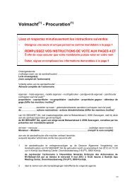
The Brickforce ® range<br />
This range of sizes has been developed to help the Design Engineer<br />
produce an efficient, cost effective, reinforced masonry design utilising a<br />
product format which was originally used in 1918.<br />
Structural Brickforce ® is manufactured in 5 diameters, starting with 3.00<br />
mm to match the Code of Practice minimum. With this range of sizes it<br />
is possible to get closer to the optimum solution, thus reducing material<br />
costs.<br />
This flexibility gives the Design Engineer the ability to save on other<br />
materials. For example, wind posts can be designed out, top rails<br />
removed in laterally loaded panels and minimum wall widths maintained.<br />
Masonry lintels and beams can also be achieved with the use of<br />
Brickforce ® .<br />
To assist site installation, the main wires are flattened to between 2.75<br />
and 3.00 mm with the cross wires in the same plane. This ensures lapping<br />
and crossing at intersections can be achieved within the code<br />
requirements for material thickness of 6 mm maximum build up of steel in<br />
a 10 mm bed-joint.<br />
Important notes<br />
1. Brickforce ® is now produced with a characteristic tensile strength<br />
of 500 N/mm 2 .<br />
2. The equivalent diameter of the wire is given to enable the cross<br />
sectional area to be calculated and is a minimum. The flattening<br />
process lengthens the wire and therefore reduces the cross<br />
sectional area. To compensate for this reduction, <strong>Bekaert</strong> uses<br />
a larger diameter wire initially, to ensure that after flattening the<br />
minimum equivalent diameter is as stated. An Engineer can<br />
design with confidence, knowing our Factory Quality Control<br />
Management System (QMS) has received BS EN IS09001:2000<br />
recognition.<br />
Diameter<br />
reference<br />
Minimum<br />
equivalent<br />
diameter (mm)<br />
Minimum cross<br />
sectional area<br />
(mm2)<br />
BF30 3.00 7.07 2.75<br />
BF35 3.58 10.06 2.75<br />
BF40 4.00 12.56 2.75<br />
BF45 4.50 15.91 2.75<br />
BF50 5.00 19.64 3.00<br />
Approx depth<br />
across fl ats (mm)<br />
Available in various widths<br />
Raw material<br />
Testing<br />
Welding process<br />
Manufacturing<br />
Despatch<br />
3
The Brickforce ® range<br />
Brick/block wall<br />
width<br />
The table above shows the most common widths of Brickforce ® . These<br />
are carried in stock in both stainless steel and galvanised steel finishes<br />
and for all diameters. Other sizes are available and are made to order.<br />
Product reference<br />
100 mm 140 mm 150 mm 190 mm 215 mm<br />
Brickforce ® width 60 mm 100 mm 100 mm 150 mm 175 mm<br />
As Brickforce ® is available in stainless steel and galvanised steel wire for<br />
each diameter and for various widths, each type of Brickforce ® has its<br />
own unique reference.<br />
For example:<br />
- The diameter reference BF35 is preceded by the finish type (S = stainless<br />
steel, G = galvanised steel) and followed by the product width.<br />
- Therefore, SBF35W60 is stainless steel Brickforce ® with main wires<br />
of 3.58 equivalent diameter and a width of 60 mm. (For 100 mm wide<br />
brick/block).<br />
The Royal Opera House, Covent Garden, London ©<br />
Twickenham Stadium, Twickenham, London ©<br />
✔ Stainless steel, grade 304S15<br />
(R3 - 1.4301) for external<br />
walls.<br />
✔ Galvanised finish to BS443<br />
(265 g/m2) (R13 BS EN 10244<br />
with a coating to BS EN 10020)<br />
✔ Length of strip = 2,700 mm.<br />
✔ Lap length = 225 mm.<br />
✔ Corners, T-sections, radius<br />
and other shapes are available.<br />
Benefits<br />
✔ The Design Engineer<br />
can select a suitable wire<br />
diameter for the most<br />
economic design.<br />
✔ Reduction of windposts.<br />
✔ Top rails may be omitted.<br />
✔ Centres of movement<br />
joints increased.<br />
✔ Span greater distances<br />
between supports.<br />
✔ Avoid increasing the<br />
thickness of a wall.<br />
4
Design notes<br />
All structural bed joint reinforcement is covered by BS5628 Part 2,<br />
and or EN845-3, the Code of Practice for the structural use of reinforced<br />
and pre-stressed masonry. The main points of this code in<br />
relation to bed joint reinforcement are listed ....<br />
1. For laterally loaded panels a minimum cross sectional area of reinforcement<br />
at 14 mm2 is required, placed at vertical intervals not<br />
exceeding 450 mm. Furthermore, the partial safety factor for the<br />
compressive strength of masonry should be taken from clause 27 of<br />
BS5628 Part 1.<br />
2. An increase in the limiting dimension is permissible to 60 x the effective<br />
thickness and a corresponding increase in panel area is available<br />
depending on the support conditions.<br />
3. Various design methods are acceptable, the more popular for lateral<br />
load resistance is A5 method three: Design using modified orthogonal<br />
ratio. A typical panel design using this method is shown on pages 19<br />
and 20.<br />
4. Durability and material finish are covered in Table 14 of BS5628 Part<br />
2. Galvanised material, unless coated to a minimum weight of 940 g/<br />
m2 is only for use in internal walls as the required 940 g/m2 galvanising<br />
on small diameter wires is impossible to achieve consistently. For<br />
external walls, including the inner leaf of a cavity wall, only austenitic<br />
stainless steel is used in line with EN 845-3.<br />
5. To allow bond to develop between reinforcement and mortar a maximum<br />
depth of steel of 6 mm is given, thus allowing 2 mm cover top<br />
and bottom.<br />
Important notes<br />
The maximum depth of reinforcement becomes critical at laps, corners,<br />
intersections and wall tie positions - hence <strong>Bekaert</strong>'s preference<br />
for flattened wires. This flattened profile, together with the integral<br />
cross wires, enables larger diameters of wire to be used without an<br />
increase in the overall steel thickness, therefore, reinforcement continuity<br />
can be maintained. By using welded corner units and T-sections<br />
etc., within the maximum steel depth of 6 mm the bricklayer has no<br />
problems with layer build up, and the bed joint thickness remains as<br />
designed.<br />
Also, by using a larger diameter at 450 mm centres instead of a<br />
smaller one at 225 mm centres, minimum quantities of reinforcement<br />
are used, construction is faster and wall ties can be easily<br />
positioned in the intermediate bed joints.<br />
6. The minimum cover stipulated in BS5628 Part 2 is 15 mm, but it<br />
is usual when designing to use 20 mm. This will allow for either<br />
raked joints or give the bricklayer 5 mm tolerance when laying the<br />
reinforcement.<br />
7. The tables for 215 mm wide block assume the use of collar jointed<br />
wall construction in accordance with BS5628 Part 1. The reinforcement<br />
used in <strong>Bekaert</strong> Bricktie, is made from the same range<br />
of wire diameters as Brickforce ® , but has 20 mm x 3 mm cross<br />
pieces, enabling the wall to be designed as a single leaf.<br />
Brickforce ®<br />
Bricktie<br />
5
<strong>Load</strong> tables for reinforcement<br />
of laterally loaded masonry panels<br />
To demonstrate the flexibility of our Brickforce ® range, a set of tables has been developed showing the<br />
ultimate lateral load capacities for various panel sizes using different diameters of Brickforce ® wires.<br />
These tables should also prove invaluable during initial overall design as a guide to the selection of panel<br />
lengths, superstructure layout, quantities etc., before final design is required. Assistance with these tables, or<br />
panels with openings is available by contacting our technical team.<br />
Notes<br />
on design tables<br />
1. The load tables give the ultimate<br />
load capacity (in kN/<br />
M2) of various unreinforced<br />
and reinforced wall panels<br />
under uniform lateral loading.<br />
2. Partial safety factors adopted:<br />
γm = 3.0, γmm= 2.3, γms<br />
= 1.15.<br />
3. These tables have been<br />
prepared in accordance with<br />
BS5628 Part 2 using the A5<br />
method 3. Characteristic tensile<br />
strength of steel = 500 N/<br />
mm2.<br />
4. Precompression due to self<br />
weight of the wall panel has<br />
been taken into consideration.<br />
Block Density = 6.5 kN/m3.<br />
Brick Wall Density = 20 kN/<br />
m3. Mortar Designation =<br />
(iii).<br />
5. Block strength and brick<br />
“water absorption” are specified<br />
in tables.<br />
6. Bricks to have minimum compressive<br />
strength of 15 kN/<br />
m2.<br />
7. For Brickforce ® coding details<br />
e.g. BF30, BF35, see page 3.<br />
8. Brickforce ® reference<br />
selected must be prefixed by<br />
either ‘S’ for stainless steel<br />
(external walls) or ‘G’ for galvanised<br />
steel (internal walls).<br />
E.g. SBF4OW60 is stainless<br />
Brickforce ® 4 mm diameter<br />
with a width of 60 mm.<br />
Use of tables<br />
1. Check limiting dimensions of panel. This table also demonstrates<br />
how a block width can be maintained by reinforcing with Brickforce ®<br />
rather than increasing the block thickness (e.g. 6,000 unreinforced =<br />
140 block: 6,000 reinforced = 100 block with Brickforce ® ).<br />
2. Check limiting area of panel. This table shows increases in area<br />
available by using Brickforce ® , as indicated in the Code of Practice<br />
BS5628 Part 2. If designing a single leaf wall, the burgundy figures in<br />
the panel capacity tables show panel sizes complying with the code<br />
requirements. The blue figures are for use when considering the leaf<br />
to be part of a cavity wall and the limiting area should be checked<br />
from the table.<br />
3. Cavity walls. Look up relevant wall types and thickness as below and<br />
add together to give ultimate panel capacity:<br />
a) Unreinforced 102, brick outer leaf page 8, and reinforced inner leaf<br />
pages 9 to 16.<br />
b) Both leaves reinforced pages 9 to 16.<br />
4. Single Leaf walls. Use tables on pages 9 to 16.<br />
5. Where the enhancement of lateral load capacity of a panel is greater<br />
than 50% it is advisable to check serviceability and deflection.<br />
6. For any wall type not included in these tables please contact our<br />
Technical Department.<br />
7. Product Coding. The product code is a build up of:<br />
a) The finish.<br />
b) Type of product BF = Brickforce ® .<br />
c) Wire diameter.<br />
d) Overall width of product e.g.<br />
SBF45W150 Stainless Brickforce ® 4.5 mm diameter, 150 mm wide.<br />
GBF40W100 Galvanised Brickforce ® 4.00 mm diameter, 100 mm<br />
wide.<br />
Product Code<br />
6
Limiting dimensions and areas<br />
Single leaf wall<br />
Unreinforced<br />
50 x eff. thickness<br />
Reinforced<br />
60 x eff. thickness<br />
102 brick 5,100 mm 6,120 mm<br />
100 block 5,000 mm 6,000 mm<br />
140 block 7,000 mm 8,400 mm<br />
215 block 10,750 mm 12,900 mm<br />
Cavity wall<br />
102/100 6,733 mm 8,080 mm<br />
102/140 8,066 mm 9,680 mm<br />
102/215 10,566 mm 12,680 mm<br />
100/100 6,667 mm 8,000 mm<br />
100/140 8,000 mm 9,600 mm<br />
100/215 10,750 mm 12,900 mm<br />
140/140 9,333 mm 11,200 mm<br />
Effective<br />
thickness<br />
(mm)<br />
unreinforced reinforced unreinforced reinforced unreinforced reinforced unreinforced reinforced<br />
Single leaf wall m 2 m 2 m 2 m 2 m 2 m 2 m 2 m 2<br />
102 brick 102 15.61 18.73 14.05 16.65 23.41 28.09 21.07 24.97<br />
100 block 100 15.00 18.00 13.50 16.00 22.50 27.00 20.25 24.00<br />
140 block 140 29.40 35.28 26.46 31.36 44.10 52.92 39.69 47.04<br />
215 block 215 69.34 83.20 62.40 73.96 104.01 124.81 93.61 110.94<br />
Cavity wall Note: The figures below assume a cavity width of less than 100 mm.<br />
102/100 134.67 27.20 32.64 24.48 29.02 40.81 48.97 36.73 43.53<br />
102/140 161.33 39.04 46.85 35.14 41.64 58.56 70.27 52.71 62.47<br />
102/215 211.33 66.99 80.39 60.29 71.46 100.49 120.58 90.44 107.18<br />
100/100 133.33 26.67 32.00 24.00 28.44 40.00 48.00 36.00 42.66<br />
100/140 160.00 38.40 46.08 34.56 40.96 57.60 69.12 51.84 61.44<br />
100/215 210.00 66.15 79.38 59.53 70.56 99.22 119.07 89.30 105.84<br />
140/140 186.67 52.27 62.72 47.04 55.75 78.40 94.08 70.56 83.63<br />
7
Panels with openings<br />
As an alternative to using additional supports such as windposts to cope<br />
with doors and windows in masonry panels, it is possible in the majority<br />
of situations to use Brickforce ® in the bed joints to enhance the wind load<br />
capacity of the panel. This is generally a far more cost-effective solution.<br />
Panel designed with bands of<br />
Brickforce ® above and below<br />
window, carrying wind load from<br />
central window band.<br />
Panel designed with a band of<br />
Brickforce ® over the door, carrying<br />
wind load from panel below.<br />
It is advisable to check the panel<br />
at the side of the door, although<br />
in most cases it has sufficient<br />
capacity unreinforced.<br />
If masonry between windows can<br />
span vertically the depth of the<br />
window (carrying wind load from<br />
adjacent windows), the panel<br />
may be designed with bands of<br />
Brickforce ® above and below.<br />
Invariably in this situation a support<br />
is required adjacent to the<br />
door, and the panel divided into<br />
sub-panels.<br />
Typical window and door panel solutions<br />
The following examples have<br />
been produced to demonstrate<br />
the capacity and flexibility of the<br />
Brickforce ® range and certain<br />
assumptions have<br />
been made.<br />
✔ Outer leaf brickwork:<br />
- 7%-12% water absorption.<br />
- 20 N/mm2 compressive<br />
strength.<br />
- 2,000 Kg/m2 density.<br />
✔ Inner leaf blockwork:<br />
- 3.5 N/mm2 compressive<br />
strength<br />
- 1,450 Kg/m2 density.<br />
It should also be noted that<br />
the Brickforce ® , which initially<br />
has been designed to carry the<br />
lateral wind loading, will also<br />
provide crack control for the<br />
openings<br />
✔ Mortar designation: (iii)<br />
✔ Characteristic tensile strength<br />
of steel: 500 N/mm2.<br />
✔ Window assumed in middle<br />
third of panel.<br />
✔ Door assumed in middle third<br />
of panel.<br />
Note: If the door is outside the middle third, in the majority of cases the panel at the side of the<br />
door (2.1 m high) will have sufficient capacity unreinforced, but in extreme cases may require reinforcement.<br />
Contact <strong>Bekaert</strong> Technical Department.<br />
17
<strong>Tables</strong> for panels with openings<br />
Typical window panel<br />
Typical panel above door<br />
Typical panel below window<br />
3,000 mm<br />
Factored lateral load capacities kN/m 2<br />
3,000 mm<br />
1,200 mm<br />
900 mm<br />
1,200 mm<br />
2,100 mm<br />
X<br />
1,500 mm<br />
Wall makeup-102/Cavity/1OO<br />
With Brickforce<br />
SBF30 SBF35 SBF40 SBF45 SBF50 length of SBF30 SBF35 SBF40 SBF45 SBF50<br />
W60 W60 W60 W60 W60 panel (X) W100 W100 W100 W100 W100<br />
1.76 2.27 2.64 3.10 3.53 3,000 2.24 2.89 3.37 3.97 4.56<br />
1.25 1.56 1.78 2.05 2.31 4,000 1.60 1.99 2.28 2.64 2.99<br />
1.00 1.20 1.36 1.54 1.72 5,000 1.27 1.54 1.74 1.99 2.22<br />
0.85 1.00 1.12 1.17 1.38 6,000 1.09 1.29 1.43 1.61 1.78<br />
0.75 0.87 0.96 1.07 1.17 7,000 0.97 1.12 1.24 1.38 1.51<br />
0.69 0.79 0.86 0.94 1.02 8,000 0.89 1.01 1.10 1.22 1.32<br />
® Wall makeup-102/Cavity/14O<br />
in both leaves at 225 centres<br />
With Brickforce ® in both leaves at 225 centres<br />
Factored lateral load capacities kN/m 2<br />
Wall makeup-102/Cavity/1OO<br />
With Brickforce<br />
SBF30 SBF35 SBF40 SBF45 SBF50 length of SBF30 SBF35 SBF40 SBF45 SBF50<br />
W60 W60 W60 W60 W60 panel (X) W100 W100 W100 W100 W100<br />
1.00 1.26 1.46 1.70 1.93 3,000 1.27 1.61 1.86 2.18 2.49<br />
0.68 0.84 0.96 1.10 1.24 4,000 0.86 1.07 1.22 1.41 1.59<br />
0.50 0.62 0.71 0.81 0.90 5,000 0.64 0.80 0.91 1.04 1.16<br />
0.39 0.49 0.56 0.64 0.71 6,000 0.50 0.62 0.71 0.82 0.91<br />
0.32 0.40 0.45 0.52 0.58 7,000 0.41 0.51 0.58 0.66 0.74<br />
0.27 0.34 0.38 0.43 0.48 8,000 0.35 0.43 0.49 0.55 0.62<br />
® Wall makeup-102/Cavity/14O<br />
in both leaves over door only at 225 centres<br />
With Brickforce ® in both leaves over door only at 225 centres<br />
Factored lateral load capacities kN/m 2<br />
Wall makeup-102/Cavity/100<br />
With Brickforce<br />
SBF30 SBF35 SBF40 SBF45 SBF50 length of SBF30 SBF35 SBF40 SBF45 SBF50<br />
W60 W60 W60 W60 W60 panel (X) W100 W100 W100 W100 W100<br />
1.47 1.85 2.14 2.49 2.81 3,000 1.86 2.36 2.72 3.18 3.62<br />
1.00 1.24 1.41 1.62 1.81 4,000 1.27 1.58 1.80 2.07 2.34<br />
0.74 0.92 1.05 1.20 1.33 5,000 0.94 1.18 1.34 1.53 1.71<br />
0.58 0.72 0.82 0.94 1.04 6,000 0.74 0.92 1.05 1.21 1.35<br />
0.48 0.59 0.67 0.76 0.85 7,000 0.61 0.75 0.85 0.98 1.09<br />
0.41 0.50 0.56 0.64 0.71 8,000 0.52 0.64 0.72 0.82 0.91<br />
® Wall makeup-102/Cavity/140<br />
in both leaves at 225 centres<br />
With Brickforce ® in both leaves at 225 centres<br />
X<br />
900 mm<br />
X<br />
18
Design calculations<br />
Typical design of wall panel to resist lateral loading<br />
Where lateral loading occurs, and enhanced resistance to the load is required, bed joint reinforcement should be<br />
used as required by Clause A2.4 (Annex A) of BS5628 Part 2:2000. This states that it may be<br />
assumed the wall will have enhanced lateral load resistance compared with an unreinforced wall, if<br />
reinforcement with a minimum cross sectional area of 14 mm2 is placed at vertical centres not exceeding 450<br />
mm.<br />
It is normally more economic to reinforce a wall to resist horizontal pressure than to provide alternative solutions<br />
such as intermediate piers, windposts or an increase in wall thickness.<br />
The following calculations show the design case A5 method 3 from BS5628 Part 2 using a modified<br />
orthogonal ratio. To enable this method to be used, bending moment co-efficient tables are also provided on<br />
pages 21 to 23.<br />
Consider a panel 6 metres high and 7.5 metres long, simply supported on four sides.<br />
6 m<br />
7.5 m<br />
102 brick outer/50 cavity/140 block inner<br />
Wind force unfactored = 0.50 kN/mm 2<br />
Factored = 0.5 x 1.2 = 0.6 kN/mm 2<br />
Check without reinforcement<br />
Brick compressive strength = 20 N/mm 2<br />
Water absorption = 7% - 12%<br />
Mortar designation = (iii) γm = 3.0<br />
Hence:-<br />
Characteristic compressive strength = 5.8 N/mm 2<br />
Characteristic fl exural strength parallel to bed joint = 0.4 N/mm 2<br />
Characteristic fl exural strength perpendicular to bed joint = 1.1 N/mm 2<br />
WALL PANEL: H = 6 = 0.8 Orthogonal ratio = 0.4 = 0.36 Z = 10 3 x 10² 2<br />
L 7.5 1.1 6 x 10 6<br />
Allowable = Md where Md = fkx Z ∴ α(Wkγf) L 2 = fkx Z<br />
Wind load α x L 2 γm γm<br />
∴Wkγf = 1.1 x 10 3<br />
x 102 2<br />
= 0.21 kN/m 2<br />
3.0 x 6 x 10 6<br />
x 7.5 2 From Table 8, Condition ‘E’, BS5628 Part 1<br />
x 0.05<br />
Block compressive strength = 7.0 N/mm 2<br />
Mortar designation = (iii)<br />
Characteristic compressive strength = 5.5 N/mm 2<br />
Characteristic fl exural strength parallel to bed joint = 0.22 N/mm 2<br />
Characteristic fl exural strength perpendicular to bed joint = 0.53 N/mm 2<br />
Orthogonal ratio = 0.22 = 0.42 Z = 10 3<br />
x 140 2<br />
0.53 6 x 10 6<br />
From Table 8, Condition ‘E’, BS5628 Part 1<br />
α = 0.05 Wkγf = 0.53 x 10 3<br />
x 140 2 = 0.21 kN/m 2<br />
3.0 x 6 x 10 6<br />
x 7.5 2 x 0.05<br />
Design strength of cavity wall = 0.21 + 0.21 = 0.42 kN/m
Design calculations<br />
Typical design of wall panel to resist lateral loading<br />
Therefore, we will need to enhance with Brickforce ® bed joint reinforcement using A5 method 3 (BS5628 Part 2).<br />
140 inner block<br />
Moment of resistance (vertical) = fkxZ = .22 x 3.267 x 10 6<br />
= 0.24 kNm/m<br />
γm 3.0 x 10 6<br />
Moment of resistance horizontal (steel using BF50)<br />
(5 mm equivalent diameter wires)<br />
= As fγ Z z = d (1 - 0.5 As fγ γmm) = 0.948d<br />
γms b d fk γms (0.95d max)<br />
= 19.64 x 500 x 0.948 x 116 As (one wire) = 19.64 mm 2<br />
1.15 x 10 6 d = 140 + 92 = 116 mm<br />
2 2<br />
= 0.939 kNm x 1000 b = 450 (spacing)<br />
450<br />
= 2.09 kNm/m fk = 5.5 N/mm 2<br />
(mortar iii)<br />
Modifi ed Orthogonal ratio γms = 1.15<br />
= 0.24 = 0.1148 γmm = 3.5<br />
2.09<br />
H = 0.8 fγ = 500 N/mm 2<br />
L<br />
(See copy table from Handbook to BS5628 Part 2)<br />
α = 0.078<br />
Allowable wind strength = 2.09 = 0.48 kN/m 2<br />
0.078 x 7.5 2<br />
Brick leaf remains as previous = 0.21 kN/m 2<br />
Total wind strength = 0.48 + 0.21 = 0.69<br />
> 0.6 kN/ m 2 ∴ satisfactory<br />
140 mm<br />
PANEL WORKS Therefore provide Brickforce ® SBF50W100 in inner blockwork leaf at 450 centres.<br />
92 mm<br />
70 mm<br />
116 mm<br />
20
Design tables 1<br />
Bending moment co-efficients in laterally loaded wall panels<br />
taken from handbook to bs5628 part 2<br />
Note 1<br />
Linear interpolation of m and H/L is permitted.<br />
Note 2<br />
When the dimensions of a wall are outside the range of H/L given in this table, it will usually be sufficient to<br />
calculate the moments on the basis of a simple span. For example, a panel of Type “A” having H/L less than<br />
0.3 will tend to act as a free-standing wall, whilst the same panel having H/L greater than 1.75 will tend to span<br />
horizontally.<br />
Key to support conditions<br />
denotes simply supported edge<br />
denotes free edge<br />
denotes an edge over which full<br />
continuity exists<br />
H<br />
μα<br />
L<br />
μα<br />
α α<br />
Values of α<br />
μ H<br />
0.30<br />
L<br />
0.50 0.75 1.00 1.25 1.50 1.75<br />
0.25 0.050 0.071 0.085 0.094 0.099 0.103 0.106<br />
0.20 0.054 0.075 0.089 0.097 0.102 0.105 0.108<br />
0.15 0.060 0.080 0.093 0.100 0.104 0.108 0.110<br />
0.10 0.069 0.087 0.098 0.104 0.108 0.111 0.113<br />
0.05 0.082 0.097 0.105 0.110 0.113 0.115 0.116<br />
0.25 0.039 0.053 0.062 0.068 0.071 0.073 0.075<br />
0.20 0.043 0.056 0.065 0.069 0.072 0.074 0.076<br />
0.15 0.047 0.059 0.067 0.071 0.074 0.076 0.077<br />
0.10 0.052 0.063 0.070 0.074 0.076 0.078 0.079<br />
0.05 0.060 0.069 0.074 0.077 0.079 0.080 0.081<br />
0.25 0.032 0.042 0.048 0.051 0.053 0.054 0.056<br />
0.20 0.034 0.043 0.049 0.052 0.054 0.055 0.056<br />
0.15 0.037 0.046 0.051 0.053 0.055 0.056 0.057<br />
0.10 0.041 0.048 0.053 0.055 0.056 0.057 0.058<br />
0.05 0.046 0.052 0.055 0.057 0.058 0.059 0.059<br />
21
Design tables 2<br />
Values of α<br />
μ H<br />
0.30 0.50 0.75 1.00 1.25 1.50 1.75<br />
L<br />
0.25 0.025 0.035 0.043 0.047 0.050 0.052 0.053<br />
0.20 0.027 0.038 0.044 0.048 0.051 0.053 0.054<br />
0.15 0.030 0.040 0.046 0.050 0.052 0.054 0.055<br />
0.10 0.034 0.043 0.049 0.052 0.054 0.055 0.056<br />
0.05 0.041 0.048 0.053 0.055 0.056 0.057 0.058<br />
0.25 0.023 0.042 0.059 0.071 0.080 0.087 0.091<br />
0.20 0.026 0.046 0.064 0.076 0.084 0.090 0.095<br />
0.15 0.032 0.053 0.070 0.081 0.089 0.094 0.098<br />
0.10 0.039 0.062 0.078 0.088 0.095 0.100 0.103<br />
0.05 0.054 0.076 0.090 0.098 0.103 0.107 0.109<br />
0.25 0.020 0.034 0.046 0.054 0.060 0.063 0.066<br />
0.20 0.023 0.037 0.049 0.057 0.062 0.066 0.068<br />
0.15 0.027 0.042 0.053 0.060 0.065 0.068 0.070<br />
0.10 0.032 0.048 0.058 0.064 0.068 0.071 0.073<br />
0.05 0.043 0.057 0.066 0.070 0.073 0.075 0.077<br />
0.25 0.018 0.028 0.037 0.042 0.046 0.048 0.050<br />
0.20 0.020 0.031 0.039 0.044 0.047 0.050 0.052<br />
0.15 0.023 0.034 0.042 0.046 0.049 0.051 0.053<br />
0.10 0.027 0.038 0.045 0.049 0.052 0.053 0.055<br />
0.05 0.035 0.044 0.050 0.053 0.055 0.056 0.057<br />
0.25 0.014 0.024 0.033 0.039 0.043 0.046 0.048<br />
0.20 0.016 0.027 0.035 0.041 0.045 0.047 0.049<br />
0.15 0.019 0.030 0.038 0.043 0.047 0.049 0.051<br />
0.10 0.023 0.034 0.042 0.047 0.050 0.052 0.053<br />
0.05 0.031 0.041 0.047 0.051 0.053 0.055 0.056<br />
0.25 0.011 0.021 0.030 0.036 0.040 0.043 0.046<br />
0.20 0.013 0.023 0.032 0.038 0.042 0.045 0.047<br />
0.15 0.016 0.026 0.035 0.041 0.044 0.047 0.049<br />
0.10 0.020 0.031 0.039 0.044 0.047 0.050 0.052<br />
0.05 0.027 0.038 0.045 0.049 0.052 0.053 0.055<br />
22
H<br />
Design tables 3<br />
α<br />
L<br />
μα<br />
μα<br />
α<br />
Blackpool Football Club, Blackpool ©<br />
Values of α<br />
μ H<br />
0.30<br />
L<br />
0.50 0.75 1.00 1.25 1.50 1.75<br />
0.25 0.032 0.071 0.122 0.180 0.240 0.300 0.362<br />
0.20 0.038 0.083 0.142 0.208 0.276 0.344 0.413<br />
0.15 0.048 0.100 0.173 0.250 0.329 0.408 0.488<br />
0.10 0.065 0.131 0.224 0.321 0.418 0.515 0.613<br />
0.05 0.106 0.208 0.344 0.482 0.620 0.759 0.898<br />
0.25 0.028 0.056 0.091 0.123 0.150 0.174 0.196<br />
0.20 0.033 0.064 0.103 0.136 0.165 0.190 0.211<br />
0.15 0.040 0.077 0.119 0.155 0.184 0.210 0.231<br />
0.10 0.053 0.096 0.144 0.182 0.213 0.238 0.260<br />
0.05 0.080 0.136 0.190 0.230 0.260 0.286 0.306<br />
0.25 0.021 0.044 0.073 0.101 0.127 0.150 0.170<br />
0.20 0.025 0.052 0.084 0.114 0.141 0.165 0.185<br />
0.15 0.031 0.061 0.098 0.131 0.159 0.184 0.205<br />
0.10 0.041 0.078 0.121 0.156 0.186 0.212 0.233<br />
0.05 0.064 0.114 0.164 0.204 0.235 0.260 0.281<br />
23
Reinforced masonry lintels<br />
& beams<br />
For many years Brickforce ® has been successfully used to reinforce<br />
masonry lintels over openings. Providing temporary support is used<br />
during construction, this method is cost effective as generally only two<br />
courses of Brickforce ® are required.<br />
In many cases, if Brickforce ® is being used for crack control, the lintel is<br />
redundant. The anchorage of Brickforce ® is far superior to a lintel and a<br />
more monolithic structure results.<br />
For walls being built on existing floors Brickforce ® can be used to design<br />
the wall as a vertical beam, thus reducing the load on the floor and the<br />
subsequent deflection, and also protecting against cracking in the wall<br />
finish.<br />
Software for masonry lintel/beam design is available on request.<br />
Span of Lintel Reinforcement Required<br />
1.2 metres 2 courses of SBF35W60<br />
1.5 metres 2 courses of SBF35W60<br />
1.8 metres 2 courses of SBF40W60<br />
2.1 metres 2 courses of SBF40W60<br />
2.4 metres 2 courses of SBF50W60<br />
Note: Assuming lintel is only carrying its self weight.<br />
i.e. no floor loads, roof loads etc.<br />
Design advice possible<br />
on request<br />
✔ Laterally loaded panels<br />
This software will design<br />
reinforced and unreinforced,<br />
brick and block<br />
panels for the range of<br />
support conditions shown<br />
in BS5628 Part 2 Annex<br />
A.<br />
✔ Serviceability and<br />
design<br />
If more than a 50%<br />
increase in the panel<br />
capacity is achieved by<br />
reinforcing, a check can<br />
be made to ensure compliance<br />
with BS5628 Part<br />
2 Annex A.<br />
✔ Lintels and beams<br />
To demonstrate the<br />
effectiveness of using<br />
Brickforce ® to reinforce<br />
masonry lintels and self<br />
supporting beams.<br />
24
Practical hints<br />
Cover in bed joint<br />
20 mm<br />
cover<br />
10 mm<br />
bed joint<br />
20 mm<br />
cover<br />
Note: Flattened wires allow wall ties in cavity<br />
wall applications to be placed correctly<br />
with mortar cover.<br />
Laps<br />
With BRC Brickforce ® 225 laps may be<br />
achieved in two ways:<br />
(i) Side<br />
by side<br />
(ii) Over<br />
and under<br />
225 mm lap<br />
225 mm lap<br />
Overall thickness less than 6 mm<br />
Method (ii) ensures wire cover corresponds<br />
with the design.<br />
Movement joints<br />
20 mm<br />
20 mm<br />
Positions of laps<br />
225 mm<br />
min<br />
20 mm 20 mm<br />
Stagger the laps<br />
to suit panel sizes<br />
Joint fi ller<br />
Note: Centres of movement joints may be<br />
extended with use of bed joint reinforcement.<br />
225 mm<br />
min<br />
Laps in bed joint reinforcement should<br />
always be staggered.<br />
25
Development,<br />
testing and quality control<br />
Brickforce ® together with <strong>Bekaert</strong>’s other masonry reinforcement<br />
products is manufactured with CARES approval. Our Company<br />
Quality Management Systems (QMS) have also received BS EN IS0<br />
9001:2000 recognition.<br />
To assist in product traceability, each strip of Brickforce ® is ink jetted at<br />
regular intervals along one wire with its reference and a manufacturing<br />
code. This ensures that the bricklayer uses the correct product and helps<br />
the Engineer to easily check on his specification - ensuring every strip<br />
can be traced to the day of manufacture and the original material from<br />
which it was made.<br />
Production<br />
Brickforce ® is made and then checked to ensure that our reinforcement<br />
is in accordance with BS 5628-2 for structural reinforcement and BS<br />
EN 845-3 Specification for ancillary components for masonry. We test<br />
Brickforce ® to BS EN 1002-1:2001 Tensile Testing of Metallic Materials<br />
for Structural Reinforcement. Regular daily checks are made on the size,<br />
strength, flatness and cross-sectional area of the wire. As the flattening<br />
process also elongates the wire and reduces the diameter, the production<br />
process is started with a larger diameter wire than required, so after the<br />
flattening loss of diameter, the minimum cross sectional area as stated is<br />
achieved.<br />
Daily testing of flattened wire<br />
Checking raw material for<br />
traceability<br />
British standards<br />
Bed joint reinforcement is<br />
covered by the following<br />
British Standards to which<br />
<strong>Bekaert</strong> products conform:<br />
- BS5628 Part 2<br />
Structural bed joint reinforcement<br />
(minimum<br />
material specification and<br />
design requirements).<br />
- BS5628 Part 3<br />
The use of crack control<br />
bed joint reinforcement.<br />
- BS970, BS1554<br />
and BS 10 088<br />
Stainless steel as specified<br />
in BS5628 Part 2.<br />
- BS EN 10020<br />
with BS EN 10244 - zinc<br />
coating<br />
Galvanised steel wire for<br />
use in internal walls.<br />
Traceability code<br />
<strong>Bekaert</strong> is committed to a sustainable future.<br />
In addition to producing a range of products which enable the construction<br />
industry to create sustainable buildings, <strong>Bekaert</strong> also endeavours<br />
to reduce our own impact on the planet, and are working towards ISO<br />
14001 qualification.<br />
Our current in-house commitments include sourcing of sustainable paper<br />
for our printed literature and office use, recycling our office waste, and<br />
encouraging the use of energy efficient practices at all of our sites.<br />
In addition to most of our products incorporating a high proportion of<br />
recyclable materials, many also make use of material that has already<br />
been recycled.<br />
We continually monitor and make strenuous efforts to reduce our use, or<br />
requirement for fossil fuels or other natural resources; whether in controlling<br />
our working environment, in product packaging or delivering finished<br />
goods.<br />
26
Product testing<br />
In addition to materials testing<br />
during production, as part<br />
of our technical development,<br />
<strong>Bekaert</strong> is committed to an ongoing<br />
testing programme and<br />
the following test information<br />
is available on request:<br />
1. Bricktie CF - Comparison of<br />
strength to fish tail wall ties<br />
2. Bricktie CF - Full scale fire<br />
test for collar jointed (double<br />
leaf) wall using Tarmac<br />
Topblocks<br />
3. Bricktor ® - Performance tests<br />
for crack control<br />
4. Brickforce ® - Anchorage values<br />
and load carrying capacity<br />
We acknowledge the help of<br />
Ceram Building Technology,<br />
Stoke-on-Trent, who undertake<br />
our product testing.<br />
It is assumed that any person(s) using the information/calculations<br />
set out anywhere in this brochure is<br />
a responsible individual, qualified and experienced in<br />
masonry design and site constructional methods, and<br />
that proper cognisance will be taken of all design/constructionaI<br />
requirements to ensure sound engineering<br />
judgements are made. The correct application of <strong>Bekaert</strong><br />
bed joint reinforcement products on site is beyond the<br />
Company’s direct control. It is therefore assumed that any<br />
necessary precautions will be taken in accordance with<br />
health and safety regulations when using these products.<br />
In line with <strong>Bekaert</strong> policy of continual development and<br />
improvement, the information provided in this document<br />
is only intended for the assistance of clients and is not<br />
binding upon the company which reserves the right to<br />
alter the specifications of its products without notice.<br />
Brickforce ® ,Bricktor ® , Bricktie and Wallforce ® are all<br />
registered trademarks of <strong>Bekaert</strong>. The contents of this<br />
brochure are copyright © .<br />
Acknowledgements<br />
Fire test of reinforced wall<br />
Test load being applied<br />
Failure of un-reinforced wall<br />
We would like to thank the following organisations for their co-operation<br />
and permission to use photographs in the production of this brochure:<br />
- Twickenham Stadium, Twickenham, London - John Mowlem<br />
Construction.<br />
- The Royal Opera House, Covent Garden, London - David Barbour and<br />
Building Design Partnership.<br />
- Blackpool Football Club, Blackpool - Ballast PLC.<br />
- Stoke-on-Trent College and their staff for allowing photography of work<br />
examples.<br />
27
Free Brickforce ® panel design service<br />
As a leading supplier of masonry reinforcement, we can design masonry panels that provide structural<br />
and crack control benefits, whilst ensuring that each panel is designed to the most economical solution.<br />
To take advantage of our FREE design service, please complete this form and fax back to our in-house team<br />
of masonry reinforcement <strong>Engineers</strong> on 0114 242 7490 or post to: Technical Department, <strong>Bekaert</strong> Ltd, BU<br />
Building Products, The Gateway Business Centre, Unit 7, 5 Leeds Road, GB-Sheffield S9 3TY<br />
Name address<br />
Postcode<br />
Project<br />
Type of wall Single leaf/cavity<br />
Brick Width<br />
Strength<br />
Water absorption<br />
Cavity Width<br />
Block<br />
Date:<br />
Required by:<br />
Contact:<br />
Phone:<br />
Fax:<br />
E-mail:<br />
Width<br />
Strength<br />
Density (kg/m 3)<br />
Lateral load<br />
Design or ultimate<br />
Dimensions Add to panel types<br />
adjacent<br />
Support conditions Add to panel types<br />
adjacent<br />
Partial safety factors<br />
Vertical dead load<br />
on panel (kN/m)<br />
f = 1.4/1.2<br />
m = 3.0<br />
Plain<br />
panel<br />
Window<br />
panel<br />
Double<br />
window<br />
panel<br />
Door<br />
panel<br />
Misc.<br />
panel<br />
add<br />
details<br />
<strong>Bekaert</strong> Ltd, BU Building Products, The Gateway Business Centre, Unit 7, 5 Leeds Road, GB-Sheffi eld S9<br />
3TY, T 0114 242 7480, F 0114 242 7490, building.uk@bekaert.com, www.bekaert.com/building<br />
Made by Apunta / February 2010 / 53.10.05