ezRIBBON™| Loose Tube Ribbon Cable - Draka Communications
ezRIBBON™| Loose Tube Ribbon Cable - Draka Communications
ezRIBBON™| Loose Tube Ribbon Cable - Draka Communications

You also want an ePaper? Increase the reach of your titles
YUMPU automatically turns print PDFs into web optimized ePapers that Google loves.
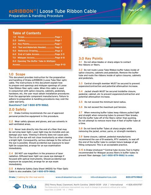
ezRIBBON | <strong>Loose</strong> <strong>Tube</strong> <strong>Ribbon</strong> <strong>Cable</strong><br />
Preparation & Handling Procedure<br />
Table of Contents<br />
1.0 Scope...................................................Page 1<br />
2.0 Safety..................................................Page 1<br />
3.0 Key Points..........................................Page 1<br />
4.0 Tool and Materials Needed.............. Page 2<br />
5.0 Reference Drawing.............................Page 2<br />
6.0 End of <strong>Cable</strong> Access..........................Page 2-5<br />
7.0 Midspan Access..................................Page 6-8<br />
8.0 Opening The Buffer <strong>Tube</strong> in MidSpan<br />
Access..........................................................Page 9-10<br />
1.0 Scope<br />
This document provides instruction for the preparation<br />
and handling of <strong>Draka</strong> ezRIBBON | <strong>Loose</strong> <strong>Tube</strong> fiber optic<br />
cable. The instructions in this document explain how<br />
to prepare end openings and midspan openings of <strong>Loose</strong><br />
<strong>Tube</strong> <strong>Ribbon</strong> fiber optic cable. When this cable is used<br />
in conjunction with splice closures, cabinets, pedestals,<br />
hardware, etc, the user must obtain installation procedures<br />
from the appropriate component manufacturers. Failure to<br />
adhere to preparation & handling procedures may void the<br />
cable warranty.<br />
Questions? Call 1-800-879-9862.<br />
2.0 Safety<br />
2.1 <strong>Draka</strong> Comteq recommends the use of approved<br />
personal protective equipment in this procedure.<br />
2.2 Wear safety glasses and gloves, and use solvents in<br />
well-ventilated areas.<br />
2.3 Never look directly into the end of a fiber that may<br />
be carrying laser light. Laser light may be invisible and can<br />
damage your eyes. Viewing it directly does not cause pain.<br />
The iris of the eye will not close involuntarily as when viewing<br />
a bright light. Consequently, serious damage to the retina of<br />
the eye is possible. Should accidental eye exposure to laser<br />
light be suspected, arrange for an eye examination<br />
immediately.<br />
2.4 DO NOT use magnifiers in the presence of laser<br />
radiation. Diffused laser light can cause eye damage if<br />
focused with optical instruments. Should accidental eye<br />
exposure be suspected, arrange for an eye exam<br />
immediately.<br />
2.5 A Material Safety Data Sheet (MSDS) for Fiber Optic<br />
<strong>Cable</strong> is also available. Call 1-800-879-9862.<br />
3.0 Key Points<br />
3.1 Do not allow blades or sharp edges to contact<br />
the ribbons or fibers.<br />
3.2 Do not route <strong>Loose</strong> <strong>Tube</strong> <strong>Ribbon</strong> buffer tubes inside of<br />
splice closures, cabinets and pedestals. Remove the buffer<br />
tube and route the ribbons inside of splice closures, cabinets<br />
and pedestals.<br />
3.3 Central strength member MUST be secured to prevent<br />
expansion/contraction and potential attenuation increase.<br />
3.4 Jacket sheath MUST be secured insidethe closure,<br />
pedestal, cabinet, etc to prevent expansion/contraction and<br />
potential attenuation increase.<br />
3.5 Do not exceed the minimum bend radius.<br />
3.6 Do not exceed the maximum pull tension.<br />
Page 1 of 10<br />
3.7 When removing buffer tubes keep ribbons pulled tight<br />
and straight when removing tubes to prevent fiber breaks.<br />
Pull the buffer tube off of the fibers rather than pushing.<br />
Do not attempt to remove more than 4 feet of buffer tube at<br />
a time.<br />
3.8 Do not bend buffer <strong>Tube</strong>s at sharp angles while<br />
removing the jacket, armor, yarns, or strength members.<br />
3.9 Some closure, cabinet, pedestal manufactures<br />
recommend the use of B-sealants, RTV sealants, to seal off<br />
the end of the buffer tube to contain future leakage of gel<br />
filling compound. This is an acceptable practice.<br />
3.10 A <strong>Draka</strong> Unishaver Central tube Access Tool is highly<br />
recommended for Midspan access fibers in buffer tubes to<br />
prevent fiber damage. Call 1-800-879-9862 to order.<br />
<strong>Draka</strong> | Cabling for the real world. www.drakaamericas.com info@drakaamericas.com 800.879.9862<br />
2512 Penny Road, Claremont, North Carolina 28610-0039 USA / International +1 828.459.9787<br />
The <strong>Draka</strong> policy of continuous improvement may result in changes to procedures without prior notice.<br />
Issue Date: 3.7.2008 - V5 / PR03
ezRIBBON | <strong>Loose</strong> <strong>Tube</strong> <strong>Ribbon</strong> <strong>Cable</strong><br />
Preparation & Handling Procedure<br />
4.0 Tools and Materials Needed<br />
[+] <strong>Cable</strong> ring cutters (Kabifix ® and Ideal ® models are<br />
recommended)<br />
[+] Utility knife or sheath knife<br />
[+] Pliers – needle nose, diagonal, or linesman<br />
[+] Diagonal cutters<br />
[+] Scissors or snips<br />
[+] Flat-tip screwdriver<br />
[+] <strong>Cable</strong> cleaning solution / D’Gel<br />
[+] Lint free wipes<br />
[+] 99% propanol alcohol<br />
[+] Disposable rags<br />
[+] Tape measure<br />
5.0 Reference Drawing<br />
Central Strength<br />
Member (CSM) .............<br />
<strong>Ribbon</strong>s<br />
(12 fiber ribbons)<br />
.............<br />
Buffer <strong>Tube</strong>s<br />
Water Blocking<br />
Tape<br />
Ripcords<br />
(2)<br />
............<br />
..................<br />
..................<br />
Page 2 of 10<br />
End Access | Tools, Checklist<br />
......................<br />
.................<br />
...........<br />
..........<br />
Binders<br />
Strength Yarns<br />
6.0 End of <strong>Cable</strong> Access Procedure<br />
Quick Reference Checklist<br />
1. Remove jacket and armoring (if applicable)<br />
[+] Measure access length and make ring cuts.<br />
[+] Slit the jacket & remove jacket. Remove the armor<br />
6” inches from end of cable.<br />
[+] Notch armor/sheath and pull ripcords.<br />
[+] Remove jacket and armor.<br />
2. Prepare the cable core.<br />
[+] Cut and remove yarns, binders, and<br />
unnecessary filler rods.<br />
[+] Separate buffer tubes from central strength<br />
member ( CSM ).<br />
[+] Cut CSM to proper length.<br />
Armor (optional)<br />
corrugated steel<br />
Jacket/Sheath<br />
3. Prepare buffer tubes and fibers.<br />
[+] Score and remove buffer tubes in max. 4 foot sections.<br />
[+] Do not route ribbon buffer tubes inside of<br />
splice closures, cabinets and pedestals. Remove the<br />
buffer tube and route the ribbons inside of splice<br />
closures, cabinets and pedestals.<br />
[+] Clean fibers and prepare for splicing.
ezRIBBON | <strong>Loose</strong> <strong>Tube</strong> <strong>Ribbon</strong> <strong>Cable</strong><br />
Preparation & Handling Procedure<br />
Step-by-Step: End of <strong>Cable</strong> Access<br />
6.1 Measure and Ring Cut #1<br />
Determine the length of cable needed to access by referring<br />
to the instructions of the closure, pedestal, cabinet, etc<br />
manufacturer. Make a Ring cut #1 at this distance from the<br />
end of the cable. Flex the cable at Ring Cut #1 to separate the<br />
jacket.<br />
CAUTION:<br />
Only a shallow cut is necessary to remove the jacket.<br />
Cutting too deeply through the jacket may result in<br />
damage to the ripcords, armor, buffer tubes, and ribbons.<br />
6.2 Ring Cut #2<br />
Make Ring Cut #2, 6 inches (15 cm) from the end of the cable,<br />
again being careful not to cut too deeply. Flex the cable at<br />
Ring Cut # 2 to separate the jacket.<br />
6.3 Remove the Jacket<br />
Using a slitter or utility knife, slit the jacket from Ring Cut #2<br />
to the end of the cable.<br />
6.4 Remove the Armor<br />
Use a utility knife to score the Armor (Ring Cut). Use pliers to<br />
peel away the Armor.<br />
6.5 Ripcord Notches<br />
Use diagonal cutters to notch the jacket (and armor, if<br />
applicable) near the ripcords. This helps start the pull<br />
of the ripcords and prevents breaking ripcord.<br />
6.6 Knot the Ripcords<br />
Tie a knot in the end of each ripcord. This will help hold the<br />
ripcord in the jaws of the pliers.<br />
Ring Cut #1 Ring Cut #2<br />
6 “<br />
Page 3 of 10<br />
End Access | Step-by-Step<br />
Slit the jacket along<br />
this line.
ezRIBBON | <strong>Loose</strong> <strong>Tube</strong> <strong>Ribbon</strong> <strong>Cable</strong><br />
Preparation & Handling Procedure<br />
6.7 Pull Ripcords<br />
Grasp one end of a ripcord in the jaws of needle nose pliers.<br />
Twist the pliers to wrap the ripcord around them, pull the<br />
ripcord through the jacket to Ring Cut #1. Cut the ripcords,<br />
leaving 1 inch exposed.<br />
NOTE:<br />
For armored cable, consult the closure, pedestal, cabinets, or<br />
hardware manufacturer procedure and make sure to<br />
leave enough armor in front of the ring-cut to be used<br />
for grounding. You may need to pull the ripcord several more<br />
inches to leave adequate armor for grounding.<br />
6.8 Remove Jacket/Armor<br />
Peel the jacket and armor (if applicable) away from the cable<br />
core and discard it. Start at the end of the cable and work<br />
toward Ring Cut #1.<br />
6.9 Remove Strength Yarns & Water Swellable Tape.<br />
Refer to the closure, pedestal, cabinet, and hardware<br />
manufacturer’s procedures to determine how much strength<br />
yarn to leave exposed for anchoring. Use snips to cut and<br />
remove the excess length of yarns and tape from the<br />
cable core.<br />
6.10 Remove Binders<br />
Use scissors and/or diagonal cutters to cut and remove<br />
binders from cable core. Binders form a criss-cross pattern to<br />
hold the core together.<br />
CAUTION:<br />
Take care to avoid piercing or cutting the buffer tubes.<br />
6.11 Separate Buffer <strong>Tube</strong>s<br />
Separate the individual buffer tubes from the central<br />
strength member (CSM) and filler rods. Keep the buffer<br />
tubes straight as possible to prevent fiber breaks.<br />
Ring Cut #1 Ring Cut #2<br />
Page 4 of 10<br />
End Access | Step-by-Step continued<br />
6 “<br />
Pull the ripcord to<br />
Ring cut #1
ezRIBBON | <strong>Loose</strong> <strong>Tube</strong> <strong>Ribbon</strong> <strong>Cable</strong><br />
Preparation & Handling Procedure<br />
6.12 Central Strength Member (CSM)<br />
Refer to the closure, pedestal, or cabinet manufacturer<br />
procedures to determine how much CSM to leave exposed for<br />
anchoring. When in doubt, leave 6 inches of CSM past the<br />
end of the jacket. Using lineman’s pliers, cut the excess CSM<br />
and filler rods and remove them from the cable core.<br />
CAUTION:<br />
Securing the central strength member inside the closure,<br />
pedestal, or cabinet is a critical element to prevent<br />
expansion/contraction and potential attenuation increases.<br />
6.13 Buffer <strong>Tube</strong> Scoring<br />
Starting from the end of the tube, measure 1 to 4 feet, then<br />
score each tube individually with rotations of the coaxial<br />
ring cutter. (Ideal ® models are recommended. Avoid using<br />
Miller ® strippers.)<br />
CAUTION:<br />
Care must be exercised in this step to prevent cutting or<br />
breaking ribbon fibers while removing the buffer tube.<br />
6.14 Removing the Buffer <strong>Tube</strong> and Exposing Fibers<br />
Grasp the tube on each side of the score mark. Flex the tube<br />
in all directions to separate the tube at the scored mark.<br />
CAUTION:<br />
Hold the buffer tube tight and straight while pulling the<br />
tube off the ribbons. Apply back-tension to the ribbons<br />
while pulling the tube off.<br />
Repeat the removal of tubes in 1 to 4 foot sections as<br />
described in steps 13 and 14 until the desired length of fiber<br />
is exposed.<br />
6.15 Fiber Cleaning<br />
Clean the ribbons with 99% propanol alcohol and lint free<br />
wipes.<br />
6.16 Gel Blocking<br />
The use of sealants (B-sealants, RTV sealants, etc.) or other<br />
commericially available gel blocking kits is recommended as<br />
additional protection to provide a seal around the ribbons<br />
and the end of the buffer tube to prevent leakage of the gel<br />
filling compound.<br />
6.17 Routing <strong>Ribbon</strong> <strong>Tube</strong>s.<br />
Do not route ribbon buffer tubes inside of splice closures,<br />
cabinets and pedestals. Remove the buffer tube and route<br />
the ribbons inside the splice closures, cabinets or pedestals.<br />
[<br />
Page 5 of 10<br />
End Access | Step-by-Step continued<br />
Pull <strong>Tube</strong> Off vs<br />
Push <strong>Tube</strong><br />
END OF PROCEDURE
ezRIBBON | <strong>Loose</strong> <strong>Tube</strong> <strong>Ribbon</strong> <strong>Cable</strong><br />
Preparation & Handling Procedure<br />
e<br />
7.0 Midspan Access Procedure<br />
Tools and Materials Needed<br />
[+] <strong>Cable</strong> ring cutter, sheath knife, or utility knife<br />
(alternatively, an ezACCESS cable jacket slitter)<br />
[+] Needle nose pliers<br />
[+] Diagonal cutters<br />
[+] Scissors or snips<br />
[+] Flat-tip screwdriver<br />
[+] Pliers<br />
[+] Procedure for closure, cabinet, pedestal<br />
hardware<br />
[+] <strong>Draka</strong> ezACCESS Midspan Access Tool<br />
[+] <strong>Cable</strong> cleaning solution or D’Gel<br />
[+] Cleaning rags<br />
[+] Lint free wipes<br />
[+] 99% propanol alcohol<br />
[+] Tape measure<br />
Quick Reference Checklist<br />
Page 6 of 10<br />
Midspan Access | Tools, Checklist<br />
Ring Cut #3 Ring Cut #1 Ring Cut # 2 Ring Cut # 4<br />
1. Remove jacket and armoring<br />
[+] Determine access point and make 2 ring cuts<br />
12” inches apart.<br />
[+] Slit jacket between ring cuts & remove.<br />
[+] Cut and pry away the armor.<br />
[+] Notch jacket and pull ripcords in equal and<br />
opposite direction.<br />
[+] Locate the switchback point and center in the opening.<br />
[+] Remove jacket and armor.<br />
2. Prepare the cable core.<br />
[+] Cut and remove yarns and binders.<br />
[+] Separate buffer tubes from central strength<br />
member ( CSM ).<br />
[+] Cut CSM and remove filler rods (if present).<br />
3. Prepare buffer tubes and fibers.<br />
[+] Clean buffer tubes (as needed).<br />
[+] Refer to “Procedure for Midspan Access in<br />
Buffer <strong>Tube</strong>s”. <strong>Draka</strong> recommends the Unishaver<br />
Central <strong>Tube</strong> Access Tool. Call 1-800-879-9862<br />
to order.<br />
4. Ensure appropriate buffer tube length.<br />
[+] Do not route ribbon buffer tubes inside of<br />
splice closures, cabinets and pedestals. Remove the<br />
buffer tube and route the ribbons inside of splice<br />
closures, cabinets and pedestals.<br />
Central Strength<br />
Member (CSM) .............<br />
<strong>Ribbon</strong>s<br />
(12 fiber ribbons)<br />
.............<br />
Buffer <strong>Tube</strong>s<br />
Water Blocking<br />
Tape<br />
Ripcords<br />
(2)<br />
............<br />
..................<br />
..................<br />
12 “<br />
Splice Point Target<br />
This length determined by closure, cabinet,<br />
pedestal manufacturer.<br />
NOTE:<br />
The switchback point on a <strong>Loose</strong> <strong>Tube</strong> <strong>Ribbon</strong> cable is<br />
approximately 18-24 inches apart.<br />
......................<br />
.................<br />
...........<br />
..........<br />
Binders<br />
Strength Yarns<br />
Armor (optional)<br />
corrugated steel<br />
Jacket/Sheath
ezRIBBON | <strong>Loose</strong> <strong>Tube</strong> <strong>Ribbon</strong> <strong>Cable</strong><br />
Preparation & Handling Procedure<br />
Step-by-Step: Midspan Access<br />
7.1 Ring Cut #1:<br />
Determine the desired access/splice point location and make a<br />
ring cut at this location. (Ring cut #1)<br />
CAUTION:<br />
Only a shallow cut is necessary to remove the jacket.<br />
Cutting too deeply through the jacket can result in<br />
unintentional damage to the ripcords, armor or<br />
buffer tubes.<br />
7.2 Ring Cut #2:<br />
Make a second ring cut 12 inches (30 cm) from Ring Cut #1.<br />
Flex the cable at Ring Cut #1 & #2 to break the jacket sheath.<br />
7.3 Slit & Remove the Jacket:<br />
Use a cable slitter or utility knife to slit the outer jacket<br />
between Ring Cut #1 and Ring Cut #2. Make several shallow<br />
cut passes. Remove the jacket in a single piece.<br />
7.4 Armor Removal: (If Applicable)<br />
Once the jacket is removed, pry open the armor and use<br />
diagonal cutters/snips to remove armor between the ring cuts.<br />
Locate the ripcords.<br />
7.5 Ripcord:<br />
Cut the ripcords in the center of the opening. Use diagonal<br />
cutters to notch the jacket (and armor, if applicable) near<br />
the ripcords. This helps start the pull of the ripcords.<br />
7.6 Knot in the Ripcords:<br />
Tie a knot in the end of each ripcord.<br />
7.7 Pull Ripcords and locate the Switchback Point:<br />
Grasp one end of a ripcord in the jaws of needle nose pliers.<br />
Turn the pliers to wrap the ripcord around them, then pull the<br />
ripcords through the jacket to the nearest switchback point<br />
(stranding reversal point). Switchbacks will occur every 18-24<br />
inches. Pull each ripcord seperately.<br />
NOTE:<br />
For armored cable, consult the closure, pedestal, cabinet,<br />
or hardware manufacturer’s procedure and make sure to<br />
leave enough armor in front of the ring cut to be used for<br />
grounding.<br />
7.8 Make Ring Cuts #3 & #4 on Equal Sides of the<br />
Switchback.<br />
Refer to the closure, pedestal, cabinet, and hardware<br />
manufacturer’s procedure to determine the required midspan<br />
length. Mark equal distance on both sides of the switchback,<br />
then make Ring cuts #3 & #4.<br />
CAUTION:<br />
Only a shallow cut is necessary to remove the jacket.<br />
Cutting too deeply through the jacket can result in<br />
unintentional damage to the ripcords, armor or ffer tubes.<br />
Page 7 of 10<br />
Midspan Access | Step-by-Step<br />
Ring Cut #3 Ring Cut #1 Ring Cut # 2 Ring Cut # 4<br />
12 “<br />
Splice Point Target<br />
This length determined by closure, cabinet,<br />
pedestal manufacturer.<br />
NOTE:<br />
The switchback point on a <strong>Loose</strong> <strong>Tube</strong> <strong>Ribbon</strong> cable is<br />
approximately 18-24 inches apart.<br />
Ring Cut #3 Ring Cut #1 Ring Cut # 2 Ring Cut # 4<br />
12 “<br />
Splice Point Target<br />
This length determined by closure, cabinet,<br />
pedestal manufacturer.<br />
NOTE:<br />
The switchback point on a <strong>Loose</strong> <strong>Tube</strong> <strong>Ribbon</strong> cable is<br />
approximately 18-24 inches apart.
ezRIBBON | <strong>Loose</strong> <strong>Tube</strong> <strong>Ribbon</strong> <strong>Cable</strong><br />
Preparation & Handling Procedure<br />
7.9 Pull Ripcords to Ring Cut #3 & Ring Cut #4.<br />
Pull the ripcords through the jacket and open the jacket to<br />
ring cuts #3 & #4. Cut ripcords, leaving 1 inch of ripcord<br />
exposed.<br />
NOTE:<br />
For armored cable, consult the closure, pedestal, cabinet, or<br />
hardware manufacturer’s procedure and make sure to<br />
leave enough armor in front of the ring cut to be used<br />
for grounding.<br />
7.10 Remove Strength Yarn & Water Blocking Tape.<br />
Refer to the closure, pedestal, cabinet, or hardware<br />
manufacturer’s procedure to determine how much strength yarn<br />
to leave exposed for anchoring. Use snips to cut and remove<br />
the excess length of yarns and tape from the cable core.<br />
7.11 Remove Binders<br />
Use a Scissors and/or diagonal cutters to cut and<br />
remove binders from around the cable core. Binders form a<br />
criss-cross pattern to hold the core together.<br />
CAUTION:<br />
Take care to avoid piercing or cutting the buffer tubes.<br />
7.12 Central Strength Member (CSM)<br />
Refer to the closure, pedestal, cabinet, or hardware<br />
manufacturer’s procedure to determine how much CSM to leave<br />
exposed for anchoring. Using lineman’s pliers, cut the excess<br />
CSM and filler rods and remove them from the cable core.<br />
CAUTION:<br />
Securing the central strength member inside the closure,<br />
pedestal, or cabinet is a critical element to prevent<br />
expansion/contraction and potential attenuation increases.<br />
7.13 Gel Blocking<br />
The use of sealants (B-sealants, RTV sealants, etc.) or other<br />
commericially available gel blocking kits is recommended as<br />
additional protection to provide a seal around the ribbons and<br />
the end of the buffer tube to prevent leakage of the gel filling<br />
compound.<br />
7.14 Routing RIbbon <strong>Tube</strong>s<br />
Do not route ribbon buffer tubes inside of splice closures,<br />
cabinets and pedestals. Remove the buffer tube and route the<br />
ribbons inside of splice closures, cabinets and pedestals.<br />
END OF PROCEDURE<br />
Page 8 of 10<br />
Midspan Access | Step-by-Step continued
ezRIBBON | <strong>Loose</strong> <strong>Tube</strong> <strong>Ribbon</strong> <strong>Cable</strong><br />
Preparation & Handling Procedure<br />
8.0 Prepare to Open The<br />
Buffer <strong>Tube</strong><br />
8.1 Prepare to Open The Buffer <strong>Tube</strong><br />
Select the proper <strong>Draka</strong> UniShaver tool size needed to access<br />
the tube. Open the tool to verify the engraved number matches<br />
the proper size of the tube being opened.<br />
8.2 Ensure the blade is correctly positioned in the tool,<br />
with the curved side of the blade facing “downhill” in the blade<br />
slot. Do not tighten blade at this point.<br />
8.3 Calibrate the blade setting in UniShaver. Each<br />
UniShaver insert is color coded to indicate size. Use the<br />
calibration standard of the same color to perform these steps.<br />
A. Insert the calibration standard into the center groove<br />
from either side of the tool. The flat edge of the<br />
standard should be facing up.<br />
B. Set the blade to rest on the calibration standard<br />
and tighten blade’s security screw.<br />
C. Remove the calibration standard.<br />
CAUTION:<br />
Calbrate or test the depth of your coaxial ring cutter<br />
before performing step 16. Failure to do so could result<br />
in cuttling of fibers. <strong>Draka</strong> recommends a shallow cut<br />
requiring mulitple rotations.<br />
8.4 Two inches (5cm) from the cable jacket ring cut #1 and #2,<br />
use a coaxial ring cutter to carefully score the tube.<br />
CAUTION:<br />
Do not route the tube inside the closure. Bending the<br />
tube inside the closure may kink the tube causing fiber<br />
damage.<br />
8.5 Open the UniShaver and position the tube in the center<br />
channel. Start the Unishaver near the black jacket. Ensure the<br />
shaved area passes over the ring cut.<br />
8.6 Open the Buffer <strong>Tube</strong><br />
Grasp the UniShaver firmly and pull from Ring Cut #1 to RIng<br />
Cut # 2.<br />
8.7 Use snips to carefully cut off the stripped buffer tube<br />
Page 9 of 10<br />
Open The Buffer <strong>Tube</strong> | Step-by-Step continued
ezRIBBON | <strong>Loose</strong> <strong>Tube</strong> <strong>Ribbon</strong> <strong>Cable</strong><br />
Preparation & Handling Procedure<br />
8.8 Remove the UniShaver from the tube by backing it off 2<br />
inches, then opening it up.<br />
8.9 Flex the tube at the scored points at ring cut #1 and #2 to<br />
snap the opened tube from the intact core tube. Separate the<br />
opened shaved tube from the ribbons and removed it.<br />
8.10 Final Preparation<br />
Using lint-free wipes and isopropyl alcohol, clean<br />
the ribbons.<br />
8.11 Remove gel filling compound at the central tube using a Qtip<br />
or similar swabbing tool. Remove gel 1 inch inside the central<br />
tube.<br />
8.12 Apply B-sealants, RTV sealants, etc. to seal off the end of<br />
the buffer tube to contain future leakage of gel filling compound.<br />
8.13 The cable is now ready for ribbon breakout and/or<br />
anchoring. Refer to that procedure.<br />
Page 10 of 10<br />
Open The Central <strong>Tube</strong> | End of Procedure<br />
END OF PROCEDURE