7 x 12 Cut-off Band Saw - Igor Chudov
7 x 12 Cut-off Band Saw - Igor Chudov
7 x 12 Cut-off Band Saw - Igor Chudov

Create successful ePaper yourself
Turn your PDF publications into a flip-book with our unique Google optimized e-Paper software.
Operating Instructions<br />
Using the vise<br />
The vise on the saw table has two jaws. The jaw<br />
closest to the right hand side of the table is the stationary<br />
jaw. This jaw is firmly secured to the table using its pivot<br />
and lock bolts. When making a straight cut the stationary<br />
jaw is at right angles to the saw blade. When making an<br />
angle cut, the stationary jaw is first loosened, then<br />
adjusted to the desired angle, then secured to the table,<br />
again.<br />
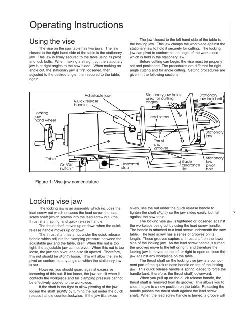
Figure 1: Vise jaw nomenclature<br />
Locking vise jaw<br />
The locking jaw is an assembly which includes the<br />
lead screw nut which encases the lead screw, the lead<br />
screw shaft (which screws into the lead screw nut,) the<br />
thrust shaft, spring, and quick release handle.<br />
The thrust shaft moves up or down when the quick<br />
release handle moves up or down.<br />
The thrust shaft has a nut under the quick release<br />
handle which adjusts the clamping pressure between the<br />
adjustable jaw and the table, itself. When this nut is too<br />
tight, the adjustable jaw cannot pivot. When this nut is too<br />
loose, the jaw can pivot, and also tilt upward. Therefore,<br />
this nut should be slightly loose. This will allow the jaw to<br />
pivot an conform to any angle at which the stationary jaw<br />
is set.<br />
However, you should guard against excessive<br />
loosening of this nut. If too loose, the jaw can tilt when it<br />
contacts the workpiece and full clamping pressure cannot<br />
be effectively applied to the workpiece.<br />
If the shaft is too tight to allow pivoting of the jaw,<br />
loosen the shaft slightly by turning the nut under the quick<br />
release handle counterclockwise. If the jaw tilts exces-<br />
The jaw closest to the left hand side of the table is<br />
the locking jaw. This jaw clamps the workpiece against the<br />
stationary jaw to hold it securely for cutting. The locking<br />
jaw can pivot to conform to the angle of the work piece<br />
which is held in the stationary jaw.<br />
Before cutting can begin, the vise must be properly<br />
set and positioned. The procedures are different for right<br />
angle cutting and for angle cutting. Setting procedures are<br />
given in the following sections.<br />
sively, use the nut under the quick release handle to<br />
tighten the shaft slightly so the jaw slides easily, but flat<br />
against the saw table.<br />
The locking vise jaw is tightened or loosened against<br />
the workpiece being cut by using the lead screw handle.<br />
The handle is attached to a lead screw underneath the saw<br />
table. The lead screw has a series of grooves on its<br />
length. These grooves capture a thrust shaft on the lower<br />
side of the locking jaw. As the lead screw handle is turned,<br />
the grooves move to the left or right, and therefore the<br />
locking jaw is moved to the left or right to open or close the<br />
jaw against any workpiece on the table.<br />
The thrust shaft on the locking vise jaw is a component<br />
part of the quick release handle on top of the locking<br />
jaw. This quick release handle is spring loaded to force the<br />
handle (and, therefore, the thrust shaft) downward.<br />
When you pull up on the quick release handle, the<br />
thrust shaft is removed from its groove. This allows you to<br />
slide the jaw to a new position on the table. Releasing the<br />
handle pushes the thrust shaft against the lead screw<br />
shaft. When the lead screw handle is turned, a groove will<br />
7