Chapter 11 Slope Stabilization and Stability of Cuts
Chapter 11 Slope Stabilization and Stability of Cuts
Chapter 11 Slope Stabilization and Stability of Cuts

You also want an ePaper? Increase the reach of your titles
YUMPU automatically turns print PDFs into web optimized ePapers that Google loves.
<strong>Chapter</strong> <strong>11</strong><br />
<strong>Slope</strong> <strong>Slope</strong> Sta Stabiliza Sta biliza bilization biliza tion <strong>and</strong><br />
<strong>and</strong><br />
Sta <strong>Stability</strong> Sta bility <strong>of</strong> <strong>of</strong> <strong>Cuts</strong> <strong>Cuts</strong> <strong>and</strong> <strong>and</strong> F FFills<br />
F ills<br />
THE OBJECTIVES OF ROUTINE ROAD CUTS AND FILLS<br />
are 1) to create space for the road template<br />
<strong>and</strong> driving surface; 2) to balance material<br />
between the cut <strong>and</strong> fill; 3) to remain stable over<br />
time; 4) to not be a source <strong>of</strong> sediment; <strong>and</strong> 5) to<br />
minimize long-term costs. L<strong>and</strong>slides <strong>and</strong> failed road<br />
cuts <strong>and</strong> fills can be a major source <strong>of</strong> sediment, they<br />
can close the road or require major repairs, <strong>and</strong> they<br />
can greatly increase road<br />
maintenance costs (Photo<br />
<strong>11</strong>.1). Vertical cut slopes<br />
should not be used unless the<br />
cut is in rock or very well<br />
cemented soil. Long-term<br />
stable cut slopes in most soils<br />
<strong>and</strong> geographic areas are<br />
typically made with about a<br />
1:1 or ¾:1 (horizontal:<br />
vertical) slope (Photo <strong>11</strong>.2).<br />
Ideally, both cut <strong>and</strong> fill slopes<br />
should be constructed so that<br />
they can be vegetated (Photo<br />
<strong>11</strong>.3), but cut slopes in dense,<br />
sterile soils or rocky material<br />
are <strong>of</strong>ten difficult to vegetate.<br />
Fill slopes should be constructed<br />
with a 1 1/2:1 or flat-<br />
“Construct cut <strong>and</strong> fill slopes that are flat enough to be<br />
stable over time <strong>and</strong> that can be revegetated.”<br />
ter slope. Over-steep fill slopes (steeper than a 1 1/2<br />
:1 slope), commonly formed by side-casting loose<br />
fill material, may continue to ravel with time, are<br />
difficult to stabilize, <strong>and</strong> are subject to sliver fill failures<br />
(Photo <strong>11</strong>.4). A rock fill can be stable with a 1<br />
1/3:1 slope. Ideally, fills should be constructed with<br />
a 2:1 or flatter slope to promote growth <strong>of</strong> vegetation<br />
<strong>and</strong> slope stability (Photo <strong>11</strong>.5). Terraces or<br />
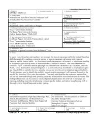
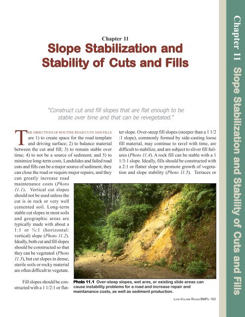
Photo Photo <strong>11</strong>.1 <strong>11</strong>.1 Over-steep slopes, wet ares, or existing slide areas can<br />
cause instability problems for a road <strong>and</strong> increase repair <strong>and</strong><br />
maintanance costs, as well as sediment production.<br />
LOW-VOLUME ROADS BMPS: 103<br />
<strong>Chapter</strong> <strong>11</strong> <strong>Slope</strong> <strong>Slope</strong> Sta Stabiliza Sta biliza bilization biliza tion <strong>and</strong> <strong>and</strong> Sta <strong>Stability</strong> Sta bility <strong>of</strong> <strong>of</strong> <strong>Cuts</strong> <strong>Cuts</strong> <strong>and</strong> F FFills<br />
F Fills<br />
ills
Photo Photo <strong>11</strong>.2 <strong>11</strong>.2 Construct cut<br />
slopes at a 3/4:1 or flatter slope<br />
in most soils for long-term<br />
stability. In well-cemented soils<br />
<strong>and</strong> rock, a 1/4:1 cut clope will<br />
usually be stable.<br />
Photo Photo <strong>11</strong>.3 <strong>11</strong>.3 <strong>11</strong>.3 A well-stabilized cut<br />
slope, with about a 1:1 slope,<br />
that is well covered with<br />
vegetation.<br />
Photo Photo <strong>11</strong>.4 <strong>11</strong>.4<br />
<strong>11</strong>.4 Avoid loose, oversteep<br />
fill slopes (steeper than 1<br />
1/5:1), particularly along<br />
streams <strong>and</strong> at drainage<br />
crossings.<br />
LOW-VOLUME ROADS BMPS: 104
enches are desirable on large fill<br />
slopes to break up the flow <strong>of</strong> surface<br />
water.<br />
Table<strong>11</strong>.1 presents a range <strong>of</strong><br />
commonly used cut <strong>and</strong> fill slope<br />
ratios appropriate for the soil <strong>and</strong><br />
rock types described. Also Figure<br />
<strong>11</strong>.1 <strong>and</strong> Figure <strong>11</strong>.2 show typical<br />
cut slope <strong>and</strong> fill slope design<br />
options, respectively, for varying<br />
slope <strong>and</strong> site conditions. Note,<br />
however, that local conditions can<br />
vary greatly, so determination <strong>of</strong><br />
stable slopes should be based<br />
upon local experience <strong>and</strong> judgment.<br />
Groundwater is the major<br />
cause <strong>of</strong> slope failures.<br />
<strong>Slope</strong> failures, or l<strong>and</strong>slides,<br />
typically occur where a slope is<br />
over-steep, where fill material is<br />
not compacted, or where cuts in<br />
natural soils encounter groundwater<br />
or zones <strong>of</strong> weak material.<br />
Good road location can <strong>of</strong>ten<br />
avoid l<strong>and</strong>slide areas <strong>and</strong> reduce<br />
slope failures. When failures do<br />
occur, the slide area should be stabilized<br />
by removing the slide material,<br />
flattening the slope, adding<br />
drainage, or using structures, as<br />
discussed below. Figure <strong>11</strong>.3<br />
shows some <strong>of</strong> the common<br />
causes <strong>of</strong> slope failures along with<br />
common solutions. Designs are<br />
typically site specific <strong>and</strong> may require<br />
input from geotechnical engineers<br />
<strong>and</strong> engineering geologists.<br />
Failures that occur typically<br />
impact road operations <strong>and</strong> can be<br />
costly to repair. Failures near<br />
streams <strong>and</strong> channel crossings<br />
have an added risk <strong>of</strong> impact to<br />
water quality.<br />
A wide range <strong>of</strong> slope stabilization<br />
measures is available to the<br />
engineer to solve slope stability<br />
Photo Photo <strong>11</strong>.5 <strong>11</strong>.5<br />
<strong>11</strong>.5 Construct fill slopes with a 1 1/2:1 or flatter slope (to<br />
promote vegetation growth) <strong>and</strong> stabilize the fill slope surface. Use<br />
benches (terraces) on large fill slopes to intercept any flow <strong>of</strong><br />
surface water.<br />
Table le <strong>11</strong>.1<br />
<strong>11</strong>.1<br />
COMMON STABLE SLOPE RATIOS<br />
FOR VARYING SOIL/ROCK CONDITIONS<br />
Soil/Rock Condition <strong>Slope</strong> Ratio (Hor:Vert)<br />
Most rock ¼:1 to ½:1<br />
Very well cemented soils ¼:1 to ½:1<br />
Most in-place soils ¾:1 to 1:1<br />
Very fractured rock 1:1 to 1 ½:1<br />
Loose coarse granular soils 1 ½:1<br />
Heavy clay soils 2:1 to 3:1<br />
S<strong>of</strong>t clay rich zones or 2:1 to 3:1<br />
wet seepage areas<br />
Fills <strong>of</strong> most soils 1 ½:1 to 2:1<br />
Fills <strong>of</strong> hard, angular rock 1 1/3:1<br />
Low cuts <strong>and</strong> fills (
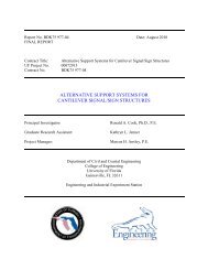
Figur igur igure igur e <strong>11</strong>.1 <strong>11</strong>.1 Cut slope design options.<br />
a. Balanced Cut <strong>and</strong> Fill<br />
b. Full Bench Cut<br />
c. Through Cut<br />
Use a Balanced Cut <strong>and</strong> Fill<br />
Section for Most Construction<br />
on Hill <strong>Slope</strong>s.<br />
LOW-VOLUME ROADS BMPS: 106<br />
Low Cut<br />
Can be Steep<br />
or Flatter<br />
2:1<br />
2:1 Typical<br />
Fill<br />
Road<br />
Road<br />
Use Full Bench <strong>Cuts</strong> When the<br />
Ground <strong>Slope</strong>s Exceed +/- 60%<br />
Road<br />
¼:1<br />
Cut<br />
Typical Rock<br />
Cut <strong>Slope</strong>s<br />
¼:1 to ½:1<br />
½:1<br />
¾:1<br />
1:1<br />
¾:1 to 1:1<br />
Natural Ground<br />
0-60% Ground slopes<br />
Typical Cut <strong>Slope</strong>s in<br />
Most Soils ¾:1 to 1:1<br />
High Cut<br />
Typically Steeper<br />
Where Stable<br />
60% +<br />
0 - 60%
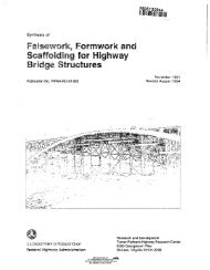
Figur igur igure igure<br />
e <strong>11</strong>.2 <strong>11</strong>.2 Fill slope design options<br />
a. Typical Fill<br />
Slash<br />
b. Benched <strong>Slope</strong> Fill with<br />
Layer Placement<br />
Slash<br />
c. Reinforced Fill<br />
Typically place fill on<br />
a 2:1 or flatter slope.<br />
Note: When possible, use a 2:1<br />
or flatter fill slope to promote<br />
revegetation.<br />
Reinforced fills are used on<br />
steep ground as an<br />
alternative to retaining<br />
structures. The 1:1 (Oversteep)<br />
face usually requires<br />
stabilization.<br />
d. Through Fill<br />
Note: Side-cast fill material<br />
only on gentle slopes, away<br />
from streams.<br />
1 1/2:1 Typical<br />
Long fill<br />
slope<br />
2:1<br />
Road<br />
Scarify <strong>and</strong> remove<br />
organic material<br />
Road<br />
Drain<br />
Natural ground<br />
Road<br />
On ground where slopes exceed 40 - 45%, construct<br />
benches +/- 3 m wide or wide enough<br />
for excavation <strong>and</strong> compaction equipment.<br />
1:1<br />
Road<br />
Geogrid or geotextile<br />
reinforcement layers<br />
3:1<br />
0-40%<br />
Ground slope<br />
Typically<br />
60% +<br />
40-60%<br />
Fill material placed in layers . Use<br />
lifts 15-30 cm thick. Compact to<br />
specified density or wheel roll<br />
each layer.<br />
Short fill<br />
slope<br />
0-40%<br />
LOW-VOLUME ROADS BMPS: 107
Figur igur igur igure igur e <strong>11</strong>.3 <strong>11</strong>.3 <strong>Slope</strong> problems <strong>and</strong> solutions with stabilization measures.<br />
LOW-VOLUME ROADS BMPS: 108<br />
The Problem<br />
Oversteep (near<br />
vertical) cutslope Cut failure<br />
Cut slope laid back<br />
to a stable angle<br />
Uncontrolled<br />
water Fill failure in<br />
oversteep or<br />
uncompacted<br />
fill material<br />
1:1<br />
Rock buttress<br />
with underdrain<br />
Note: This drawing shows a<br />
variety <strong>of</strong> slope stabilization<br />
measures which can be used to<br />
stabilize cuts <strong>and</strong> fills.<br />
Cut slope<br />
failure<br />
Original<br />
oversteepened<br />
slope<br />
Solutions<br />
Potential fill<br />
failure surface<br />
Fill compacted in<br />
15-30 cm thick layers<br />
2:1<br />
Subdrainage<br />
Vegetation on fill<br />
slope surface,<br />
preferably 2:1 or<br />
flatter<br />
Loose<br />
sidecast fill<br />
on a steep<br />
slope<br />
Retaining structure
Photo Photo <strong>11</strong>.6 <strong>11</strong>.6 Simple h<strong>and</strong> compaction behind a low rock wall. Compaction<br />
is important behind any retaining structure or fill. It can be<br />
achieved by h<strong>and</strong> or, preferably, using equipment such as a wacker<br />
or small compactor.<br />
problems <strong>and</strong> cross an unstable<br />
area. In most excavation <strong>and</strong> embankment<br />
work, relatively flat<br />
slopes, good compaction, <strong>and</strong><br />
adding needed drainage will typically<br />
eliminate routine instability<br />
problems (Photo <strong>11</strong>.6). Once a<br />
failure has occurred, the most appropriate<br />
stabilization measure<br />
will depend on site-specific conditions<br />
such as the size <strong>of</strong> the slide,<br />
soil type, road use, alignment constraints,<br />
<strong>and</strong> the cause <strong>of</strong> the failure.<br />
Here are a range <strong>of</strong> common<br />
slope stabilization options appropriate<br />
for low-volume roads, presented<br />
roughly from simplest <strong>and</strong><br />
least expensive, to the most complex<br />
<strong>and</strong> expensive:<br />
• Simply remove the slide<br />
material.<br />
• Ramp over or align the road<br />
around the slide.<br />
• Revegetate the slope <strong>and</strong><br />
add spot stabilization (See<br />
Photo 13.10).<br />
• Flatten or reconstruct the<br />
slope.<br />
• Raise or lower the road level<br />
to buttress the cut or remove<br />
weight from the slide,<br />
respectively.<br />
• Relocate the road to a new<br />
stable location.<br />
• Install slope drainage such as<br />
deep cut<strong>of</strong>f trenches or<br />
dewater with horizontal<br />
drains.<br />
• Design <strong>and</strong> construct buttresses<br />
(Photo <strong>11</strong>.7), retaining<br />
structures, or rock<br />
anchors.<br />
Retaining structures are relatively<br />
expensive but necessary in<br />
steep areas to gain roadway space<br />
or to support the roadbed on a<br />
steep slope, rather than make a<br />
large cut into the hillside. They can<br />
also be used for slope stabilization.<br />
Figure <strong>11</strong>.4 (a <strong>and</strong> b) presents<br />
information on common<br />
types <strong>of</strong> retaining walls <strong>and</strong> simple<br />
design criteria for rock walls,<br />
where the base width is commonly<br />
0.7 times the wall height (Photo<br />
<strong>11</strong>.8). Figure <strong>11</strong>.4c presents common<br />
gabion gravity wall designs<br />
<strong>and</strong> basket configurations for<br />
varying wall heights. Gabion<br />
structures are very commonly<br />
used for walls up to 6 meters high,<br />
particularly because they use locally<br />
available rock <strong>and</strong> are labor<br />
intensive (Photo <strong>11</strong>.9).<br />
Photo Photo Photo <strong>11</strong>.7 <strong>11</strong>.7 A drained rock buttress can be used to stabilize a cut<br />
slope failure area.<br />
LOW-VOLUME ROADS BMPS: 109
Figure <strong>11</strong>.4 Construction <strong>of</strong> various types <strong>of</strong> retaining structures. (Adapted from Gray & Leiser, 1982)<br />
a. a. Common Types <strong>of</strong> Retaining Structures.<br />
Hmax = 5 meters<br />
Brick or Masonry<br />
Piles<br />
0.3-0.5 m<br />
Stretcher<br />
High Rock Wall<br />
Configuration<br />
LOW-VOLUME ROADS BMPS: <strong>11</strong>0<br />
2<br />
“H" Piles<br />
Crib Wall<br />
Rock<br />
Road<br />
Headers<br />
b. Typical Rock Wall Construction.<br />
1<br />
0.7 H<br />
Gravity Walls<br />
Aggregate<br />
Fill<br />
Concrete<br />
Keys<br />
Facing<br />
For<br />
H = 0.5 m, W = 0.2 m<br />
H = 1.0 m, W = 0.4 m<br />
H = 1.5 m, W = 0.7 m<br />
H = 2.0 m, W = 1.0 m<br />
Reinforced Concrete<br />
Concrete with Counterforts<br />
Gabion Wall<br />
Reinforced Soil<br />
Counterfort<br />
Reinforced Soil Wall<br />
½ : 1 to<br />
Vertical<br />
Width<br />
(W)<br />
Rock Height<br />
(H)<br />
± 70 cm<br />
Rock<br />
Low Rock Wall Configuration
Figure <strong>11</strong>.4 Continued. (Adapted from Gray & Leiser, 1982)<br />
H<br />
H<br />
6<br />
1<br />
20"<br />
B<br />
B<br />
1<br />
2<br />
4<br />
3<br />
5<br />
6<br />
Flat Backfill (smooth face)<br />
1<br />
1<br />
2<br />
3<br />
4<br />
5<br />
6<br />
1.5<br />
β = 34°<br />
No <strong>of</strong><br />
levels<br />
No. <strong>of</strong><br />
levels<br />
Fill at 1 1/2:1 (face with steps)<br />
No. <strong>of</strong><br />
gabions<br />
(per<br />
width)<br />
b. St<strong>and</strong>ard design for Gabion Retaining Structures up to 20 feet in height (6 meters) with<br />
flat or sloping backfill.<br />
H<br />
H<br />
1 3' 3" 3' 3" 1<br />
2 6' 6" 4' <strong>11</strong>" <strong>11</strong>/2<br />
3 9' 9" 6' 6" 2<br />
4 13' 1" 8' 2" 21/2<br />
5 16' 4" 9' 9" 3<br />
6 19' 7" <strong>11</strong>' 5" 31/2<br />
B<br />
B<br />
No. <strong>of</strong><br />
gabions<br />
(per<br />
width)<br />
1 3' 3" 3' 3" 1<br />
2 6' 6" 4' 3" <strong>11</strong>/2<br />
3 9' 9" 5' 3" 2<br />
4 13' 1" 6' 6" 2<br />
5 16' 4" 8' 2" 21/2<br />
6 19' 7" 9' 9" 3<br />
Note: Loading conditions are for silty s<strong>and</strong> to s<strong>and</strong> <strong>and</strong> gravel back fill. For finer or clay rich soils,<br />
earth pressure on the wall will increase <strong>and</strong> the wall base width (B) will have to increase for each<br />
height. Backfill weight = <strong>11</strong>0 pcf. (1.8 Tons/m 3 ) (1,762 kg/m 3 )<br />
- Safe against overturning for soils with a minimum bearing capacity <strong>of</strong> 2 Tons/foot 2 (19,500 kg/m 2 )<br />
- For flat or sloping backfills, either a flat or stepped face may be used.<br />
LOW-VOLUME ROADS BMPS: <strong>11</strong>1
For low to high walls in many<br />
geographic areas today, Mechanically<br />
Stabilized Earth (MSE), or<br />
“Reinforced Soil” structures are<br />
the least expensive type <strong>of</strong> wall<br />
available. They are simple to build,<br />
<strong>and</strong> <strong>of</strong>ten they can use on-site<br />
granular backfill material. They<br />
are commonly constructed using<br />
layers <strong>of</strong> geotextile or welded wire<br />
PRACTICES TO<br />
AVOID<br />
• Constructing vertical cut<br />
slopes (except in very well<br />
cemented soils <strong>and</strong> rock).<br />
• Road locations <strong>and</strong> construction<br />
practices where<br />
the toe <strong>of</strong> the fill ends up in<br />
the creek. Do not use sidecast<br />
fill placement methods<br />
on steep slopes next to<br />
streams.<br />
• Placing fills or “side-casting”<br />
materials on natural ground<br />
slopes steeper than 60%.<br />
• Road locations in areas <strong>of</strong><br />
known instability.<br />
• Leaving cut slopes <strong>and</strong>, particularly,<br />
fill slopes barren<br />
<strong>and</strong> exposed to erosion.<br />
LOW-VOLUME ROADS BMPS: <strong>11</strong>2<br />
placed in lifts 15 to 45 cm apart<br />
in the soil, thus adding tensile reinforcement<br />
to the soil (see Figure<br />
6.3e). Driven “H” piles or<br />
sheet piles, with or without tiebacks,<br />
are relatively expensive but<br />
are <strong>of</strong>ten the most environmentally<br />
acceptable type <strong>of</strong> wall. They<br />
cause less site disturbance than<br />
gravity or MSE structures that re-<br />
quire a large foundation excavation.<br />
Most types <strong>of</strong> retaining<br />
structures <strong>and</strong> designs provided<br />
by manufacturers are internally<br />
stable for the specified use, site<br />
conditions, <strong>and</strong> height. Most wall<br />
failures occur due to foundation<br />
failure. Thus structures must be<br />
placed on a good foundation, such<br />
as bedrock or firm, in-place soil.<br />
Photo Photo <strong>11</strong>.8 <strong>11</strong>.8<br />
<strong>11</strong>.8 Use physical slope stabilization methods, such as<br />
retaining walls, reinforced fills, or rock buttresses where necessary<br />
in areas <strong>of</strong> space limitation on steep slopes.<br />
Photo Photo <strong>11</strong>.9 <strong>11</strong>.9<br />
<strong>11</strong>.9 Gabions are a commonly used type <strong>of</strong> low gravity<br />
retaining structure because they use locally available rock <strong>and</strong> are<br />
relatively inexpensive.
• Use balanced cut <strong>and</strong> fill<br />
construction in most<br />
terrain to minimize<br />
earthwork (Figure <strong>11</strong>.1a).<br />
• On steep ground (>60%<br />
slope) use full bench<br />
construction. Consider<br />
constructing a narrow,<br />
single lane road with intervisible<br />
turnouts to minimize<br />
excavation (Figure<br />
<strong>11</strong>.1b).<br />
• Construct cut slopes in<br />
most soils using a cut<br />
slope ratio <strong>of</strong> 3/4:1 to 1:1<br />
(horizontal: vertical)<br />
(Figure <strong>11</strong>.1). Use flatter<br />
cut slopes in coarse granular<br />
<strong>and</strong> unconsolidated<br />
soils, in wet areas, <strong>and</strong> in<br />
s<strong>of</strong>t or clay-rich soils. Use<br />
relatively flat cut slopes<br />
(2:1 or flatter) for low<br />
(
RECOMMENDED<br />
PRACTICES<br />
(continued)<br />
(Photo <strong>11</strong>.<strong>11</strong>). Wall backfill<br />
is typically compacted<br />
to 95% <strong>of</strong> the AASHTO<br />
T-99 maximum density.<br />
• Use retaining structures to<br />
gain roadway width in<br />
steep terrain.<br />
• Place retaining structures<br />
only upon good foundation<br />
materials, such as<br />
bedrock or firm, in-place<br />
soils (Photo <strong>11</strong>.12).<br />
Photo Photo <strong>11</strong>.<strong>11</strong> <strong>11</strong>.<strong>11</strong><br />
<strong>11</strong>.<strong>11</strong> A tire-faced,<br />
mechanically stabilized earth<br />
(MSE) retaining wall, with layers<br />
<strong>of</strong> geotextile reinforcement,<br />
being used to gain road width in<br />
a fill failure area. MSE<br />
(reinforced soil) structures are<br />
<strong>of</strong>ten the least expensive<br />
retaining structure available.<br />
Welded wire MSE walls are also<br />
commonly used.<br />
Photo Photo <strong>11</strong>.12 <strong>11</strong>.12<br />
<strong>11</strong>.12 A gabion retaining<br />
structure which will fail soon<br />
due to lack <strong>of</strong> a suitable<br />
foundation. All retaining<br />
structures, either mechanically<br />
stabilized earth (MSE) walls or<br />
gravity walls, require a good ood<br />
founda ounda ounda oundation<br />
ounda tion tion. tion<br />
LOW-VOLUME ROADS BMPS: <strong>11</strong>4<br />
Photo Photo <strong>11</strong>.10 <strong>11</strong>.10 A road fill failure in steep terrain which now needs<br />
either a retaining structure or a large road cut around the failure.