maintenance manual - Grindex Pump
maintenance manual - Grindex Pump
maintenance manual - Grindex Pump

You also want an ePaper? Increase the reach of your titles
YUMPU automatically turns print PDFs into web optimized ePapers that Google loves.
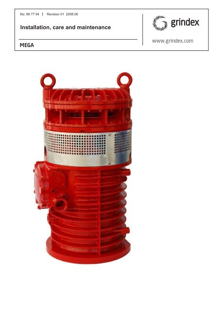
No: 89 77 94 Revision 01 2008.06<br />
Installation, care and <strong>maintenance</strong><br />
MEGA<br />
www.grindex.com
Data plate interpretation _________ 4<br />
Safety ________________________ 5<br />
Product description _________________ 6<br />
Applications _______________________________ 6<br />
Motor data ________________________________ 6<br />
Dimensions and weigts __________ 7<br />
Design________________________ 8<br />
Transportation and storage ______ 9<br />
Installation ____________________________ 9<br />
Safety precautions _________________________ 9<br />
<strong>Pump</strong> installation___________________________ 9<br />
Electrical connections _________ 10<br />
CONTENTS<br />
Operation ____________________________ 15<br />
Before starting ____________________________ 15<br />
Cleaning _________________________________ 15<br />
Care and <strong>maintenance</strong> _________ 15<br />
Safety precautions ________________________ 15<br />
Inspection________________________________ 15<br />
Recomended inspections ___________________ 16<br />
Changing the oil __________________________ 17<br />
Replacing the impeller _____________________ 17<br />
Fault tracing (Troubleshooting) ___ 26<br />
Accessories and tools _____________ 29<br />
Service log ___________________________ 30<br />
3
GENERAL DATA PLATE<br />
A<br />
B<br />
C<br />
D<br />
E<br />
F<br />
G<br />
H<br />
I<br />
DATA PLATE INTERPRETATION<br />
Data plate interpretation<br />
A <strong>Pump</strong> model<br />
B Serial No.<br />
C Rated voltage<br />
D Maximum height<br />
E Direction of impeller rotation<br />
F Direction of start reaction<br />
G Rated current<br />
H Maximum capacity<br />
I Degree of protection<br />
J Maximum submersion depth<br />
K <strong>Pump</strong> type No.<br />
L Frequency<br />
M Phases, type of current<br />
N Rated shaft power<br />
O Thermal class<br />
P Locked rotor code letter<br />
Q Country of origin<br />
R Maximum power consumption<br />
S Weight<br />
K<br />
L<br />
M<br />
N<br />
O<br />
P<br />
Q<br />
R<br />
J S<br />
4
— Only Ex-approved pumps may be used<br />
in an explosive or flammable environment.<br />
— Before starting work on the pump, make<br />
sure that the pump and the control panel<br />
are isolated from the power supply<br />
and can not be energized. This applies<br />
to the control circuit as well.<br />
— Thermal contacts must be connected to<br />
protection circuit intended for that purpose<br />
according to the approval of the<br />
product.<br />
— The pump may be used only in accordance<br />
with the approved motor data<br />
stated on the data plates.<br />
SAFETY<br />
5<br />
— This equipment must be installed in conformity<br />
to prescriptions in international<br />
or national rules ( IEC/EN 60079-14 ).<br />
— The <strong>maintenance</strong> operation must be<br />
made in conformity to the international<br />
or national standards ( IEC/EN 60079-17).<br />
— The yield stress of fastener elements in<br />
the product must be in conformity with<br />
the value specified in the table for “Material<br />
of fastener” on the approval drawing<br />
or the parts specified in the part list for<br />
the product.<br />
— <strong>Grindex</strong> disclaims all responsibility for<br />
work done by untrained, unauthorized<br />
personnel.
Applications<br />
MEGA are intended to be used for:<br />
— pumping of water which may contain abrasive<br />
particles.<br />
— pumping of raw or clean water.<br />
— pumping of ground water.<br />
MEGA are available in the following versions:<br />
N = Medium-head with an open, double suction<br />
radial-flow impeller.<br />
H = High-head with two closed radial-flow impellers.<br />
PRODUCT DESCRIPTION<br />
Liquid temperature: max. 40°C (105°F)<br />
Liquid density: max. 1100 kg/m3 (9.2 lb per US gal.)<br />
The pumped liquid may contain particles up to a size<br />
which corresponds to the openings in the strainer.<br />
The pH of the pumped liquid: 6—13.<br />
Depth of immersion: max. 75 m (250 ft).<br />
For specific data regarding your pump, please see<br />
Part List.<br />
6<br />
Motor data<br />
3 ~ 50 Hz, 2955 r/min<br />
Rated output: 90 kW<br />
Max consumption: 95 kW<br />
Voltage<br />
V<br />
Rated current<br />
A<br />
Starting current<br />
A<br />
380 155 1170<br />
400 149 1255<br />
415 142 1075<br />
440 136 1140<br />
500 118 825<br />
525 113 885<br />
550 109 915<br />
1000 60 475<br />
3 ~ 60 Hz, 3560 r/min<br />
Rated output: 104 kW, (140 hp)<br />
Max consumtion: 110 kW (148 hp)<br />
Voltage<br />
V<br />
Rated current<br />
A<br />
Starting current<br />
A<br />
380 179 1195<br />
400 170 1260<br />
440 155 1145<br />
460 149 1105<br />
575 118 850<br />
600 113 840
Weight without motor cable:<br />
N 900 kg (1984 lbs)<br />
H 985 kg (2172 lbs)<br />
DIMENSIONS & WEIGHTS<br />
N-version H-version<br />
7
1. Motor<br />
Squirrel-cage 3-phase induction motor for 50 Hz or 60<br />
Hz.<br />
The motor is started by means of direct-on-line start.<br />
The motor can be run continuously or intermittently<br />
with a maximum of 15 evenly spaced starts per hour.<br />
The stator is insulated in accordance with class H<br />
(180°C, 356°F). The motor is designed to supply its<br />
rated output at ± 5 % variation of the rated voltage.<br />
Without overheating the motor, ± 10 % variation of the<br />
rated voltage can be accepted provided that the motor<br />
does not run continuously at full load. The motor is<br />
designed to operate with a voltage imbalance of up to<br />
2 % between the phases.<br />
2. Bearings<br />
The pump bearings are designed for at least 20 000<br />
hours of operation.<br />
The main bearing of the rotor consists of two single<br />
row angular contact ball bearings.<br />
The support bearing consists of one roller bearing.<br />
When changing the bearings, and pre-greased bearings<br />
are not used, 260 g grease should be filled in the<br />
main bearings and 30 g grease in the support bearing.<br />
Grease Mobilth SHC 220 or equvalente should be<br />
used .<br />
DESIGN<br />
6<br />
4<br />
3<br />
2<br />
1<br />
5<br />
8<br />
3. Oil casing<br />
The oil lubricates and cools the seals and acts as a<br />
buffer between the pump casing and the electric motor.<br />
Pressure build-up within the oil casing is reduced by<br />
means of a built-in air volume.<br />
4. Shaft seals<br />
The pump has two mechanical seals wich provide the<br />
isolation necessary between the electric motor and the<br />
pumped liquid.<br />
Inner seal: Tungsten carbide-Tungsten carbide<br />
Outer seal: Tungsten carbide-Tungsten carbide<br />
5. Shaft<br />
The shaft is delivered with the rotor as an integral part.<br />
Shaft material: Stainless steel<br />
6. Impellers<br />
The pump is available with the following types of impellers:<br />
— one double-suction radial-flow impeller of chromium<br />
alloyed cast iron (N), or<br />
— two radial-flow impellers of nodular iron or heattreated<br />
chromium alloyed cast iron (H).<br />
Monitoring equipment<br />
Three thermal switches are incorporated in the stator.<br />
The resistance of the thermal contacts changes at<br />
125°C (260°F), close at 95°C (200°F).<br />
The monitoring equipment shall be of a design that<br />
makes automatic restart impossible.<br />
Bearing temperature is also monitored by means of a<br />
Pt100 transducer.<br />
See also "Electrical connections" and separate instructions<br />
for starters.<br />
Cooling<br />
The stator is cooled by the surrounding liquid.<br />
NOTE!<br />
Make sure that the monitoring<br />
equipment incorporated in the<br />
product is correctly connected.
TRANSPORTATION AND STORAGE<br />
The pump may be transported and stored in a vertical<br />
or horizontal position. Make sure that it cannot roll or<br />
fall over.<br />
Warning!<br />
Always lift the pump by its lifting<br />
eyes, never by the motor cable or<br />
the hose.<br />
The pump is frostproof as long as it is operating or is<br />
immersed in the liquid. If the pump is taken up when<br />
the temperature is below freezing, the impeller may<br />
freeze. The pump shall be operated for a short period<br />
after being taken up in order to expel all remaining<br />
water.<br />
Safety precautions<br />
In order to minimize the risk of accidents in connection<br />
with the service and installation work, the following<br />
rules should be followed:<br />
1. Make sure the lifting equipment is in good condition.<br />
2. Be aware of the risk of electrical accidents.<br />
3. Use a safety helmet, safety goggles and protec tive<br />
shoes.<br />
4. Do not ignore the risk of drowning.<br />
5. A first aid kit must be available.<br />
At certain installations and operation<br />
points on the pump curve<br />
the noise level 70 dB, or for the<br />
actual pump specified noise<br />
level, can be exceeded.<br />
INSTALLATION<br />
9<br />
A frozen impeller can be thawed by allowing the pump<br />
to stand immersed in the liquid for a short period before<br />
it is started. Never use a naked flame to thaw the<br />
pump.<br />
For longer periods of storage, the pump must be protected<br />
against moisture and heat. The impeller should<br />
be rotated by hand occasionally (for example every<br />
other month) to prevent the seals from sticking together.<br />
If the pump is stored for more than 6 months, this<br />
rotation is mandatory.<br />
After a long period of storage, the pump should be<br />
inspected before it is put into operation. Pay spec ial<br />
attention to the seals and the cable entry.<br />
Follow the instructions under the heading “Before<br />
starting”.<br />
<strong>Pump</strong> installation<br />
Run the cables so that they do not have any sharp<br />
bends and are not pinched.<br />
Connect the discharge connection and motor cable.<br />
See “Electrical connections”.<br />
Lower the pump into the sump.<br />
Place the pump on a base which will prevent it from<br />
sinking into a soft sump bottom. Alternati vely, the<br />
pump can be suspended by its lifting eyes just above<br />
the sump bottom.<br />
Consult your nearest <strong>Grindex</strong> representative regarding:<br />
— choice of ancillary equipment.<br />
— other problems in connection with installation.
ELECTRICAL CONNECTIONS<br />
If the pump is delivered without an installed motor<br />
cable, or if there is need for any modifications or<br />
repairs, please note that all electrical work shall be<br />
carried out under the supervision of an authorized<br />
electrician.<br />
Local codes and regulations shall be complied with.<br />
WARNING!<br />
All electrical equipment must<br />
be earthed. This applies to both<br />
pump equipment and any<br />
monitoring equipment.<br />
Failure to heed this warning may<br />
cause a lethal accident. Make<br />
sure that the earth lead is<br />
correctly connected by testing it.<br />
Check that the mains voltage and frequence agree<br />
with the specifications on the pump data plate.<br />
The motor can only be connected for different voltages<br />
by authorized work shop.<br />
Under no circumstances may the starter equipment be<br />
installed in the pump pit.<br />
If intermittent operation is prescribed (see data plate),<br />
the pump shall be provided with control equipment<br />
that provides such operation.<br />
To avoid leakage into the pump, check:<br />
— that the cable entry seal sleeve and washers conform<br />
to the outside diameter of the cable. See the<br />
parts list.<br />
— that the outer jacket on the cable is not damaged.<br />
When refitting a cable which has been used before,<br />
always cut off a short piece of the cable so that the<br />
cable entry seal sleeve does not close around the<br />
cable at the same point again.<br />
NOTE!<br />
For safety reasons, the earth lead<br />
should be longer than the phase<br />
leads. If the motor cable is jerked<br />
loose by mis take, the earth lead<br />
should be the last lead to come<br />
loose from its terminal. This applies<br />
to both ends of the cable.<br />
10<br />
Check on the data plate which connection, Y or ∆, is<br />
valid for the voltage supply. Then, depending on voltage,<br />
arrange the connection on the terminal board in<br />
accordance with Y or ∆, see figure.<br />
Connect the motor cable to the terminal board connections<br />
U1, V1, W1 and earth.<br />
Make sure that the pump is correctly earthed (grounded).<br />
Tighten the screws so that the cable entry unit bottoms<br />
out.<br />
Install the cover.<br />
Connect the motor cable to the starter equipment.<br />
Check the direction of rotation, see “Before starting”.<br />
If the direction of rotation is wrong, transpose two of<br />
the phase leads.<br />
Three thermal contacts are incorporated in the stator.<br />
Remember that the starting surge with the direct-on<br />
line start can be up to six times higher than the rated<br />
current. Make sure that the fuses or circuit breakers<br />
are of the proper amperage.<br />
The table on page 4 gives rated current and starting<br />
current. Fuse amperage and cable shall be selected in<br />
accordance with local rules and regulations. Note that<br />
with long cables, the voltage drop in the cable must<br />
be taken into consideration, since the motor’s rated<br />
voltage is the voltage that is measured at the terminal<br />
board in the pump.<br />
The overload protection in the external starter (motor<br />
protection breaker) shall, for direct-on-line start be set<br />
to the motor’s rated current as given on the data plate.<br />
NOTE!<br />
Make sure that the monitoring<br />
equipment incorporated in the<br />
product is correctly connected.
Connection plate<br />
11
SUBCAB ® 4GX/SUBCAB ® AWG,<br />
6-leads, Y<br />
Bild 49a<br />
GC L1 L2 L3 T1 T2 T3 T4<br />
GC<br />
SUBCAB ®<br />
T1<br />
T2<br />
T1 T2<br />
L1 L2<br />
L3<br />
W2 U2 V2<br />
U1 V1 W1<br />
W2 U1 V1 U2 W1 V2<br />
CABLE CHART<br />
SUBCAB ®<br />
T1 T2<br />
T1 T2 3 4<br />
T1 T2<br />
*<br />
T3 T4<br />
T3 T4<br />
SUBCAB © SUBCAB © AWG<br />
Mains Lead Lead Terminal board<br />
L1 brown red U1<br />
L2 black black W1<br />
L3 grey white V1<br />
yellow/green yellow/green<br />
Groundcheck GC yellow<br />
SUBCAB © SUBCAB © AWG<br />
Control Cable lead Cable lead Terminal board<br />
T1 T1 orange T1<br />
T2 T2 blue T2<br />
T3 T3 orange 3<br />
T4 T4 blue 4<br />
Stator leads connection:<br />
Stator lead Terminal board<br />
U1, red U1<br />
W2, black W2<br />
V1, brown V1<br />
U2, green U2<br />
W1, yellow W1<br />
V2, blue<br />
*Pt100, Main bearing<br />
V2<br />
12<br />
SUBCAB ® 4GX/SUBCAB ® AWG,<br />
6-leads, D<br />
Bild 45a<br />
GC L1 L2 L3 T1 T2 T3 T4<br />
GC<br />
SUBCAB ®<br />
T1<br />
T2<br />
T1 T2<br />
L1 L2<br />
L3<br />
W2 U2 V2<br />
U1 V1 W1<br />
W2 U1 V1 U2 W1 V2<br />
SUBCAB ®<br />
T1 T2<br />
T1 T2 3 4<br />
T1 T2<br />
*<br />
T3 T4<br />
T3 T4<br />
SUBCAB © SUBCAB © AWG<br />
Mains Lead Lead Terminal board<br />
L1 brown red U1<br />
L2 black black W1<br />
L3 grey white V1<br />
yellow/green yellow/green<br />
Groundcheck GC yellow<br />
SUBCAB © SUBCAB © AWG<br />
Control Cable lead Cable lead Terminal board<br />
T1 T1 orange T1<br />
T2 T2 blue T2<br />
T3 T3 orange 3<br />
T4 T4 blue 4<br />
Stator leads connection:<br />
Stator lead Terminal board<br />
U1, red U1<br />
W2, black W2<br />
V1, brown V1<br />
U2, green U2<br />
W1, yellow W1<br />
V2, blue<br />
*Pt100, Main bearing<br />
V2
SUBCAB ® 4GX/SUBCAB ® AWG,<br />
6-leads, YD<br />
L1 L2 L3 GC L1 L2 L3<br />
T1 T2 T3 T4<br />
L1 L2 L3 T1 T2 L1 L2 L3 T3 T4 T1 T2 T3 T4<br />
Bild 56a<br />
SUBCAB ®<br />
GC<br />
U1<br />
V1<br />
W1<br />
T1 T2<br />
SUBCAB ®<br />
W2<br />
U2<br />
V2<br />
W1 U1 W2 V2 *<br />
V1 U2<br />
CABLE CHART<br />
SUBCAB ®<br />
SUBCAB © SUBCAB © AWG<br />
Mains Lead Lead Terminal board<br />
L1 brown red U1<br />
L2 black black W1<br />
L3 grey white V1<br />
L1 brown red W2<br />
L2 black black V2<br />
L3 grey white U2<br />
yellow/green yellow/green<br />
Groundcheck GC yellow<br />
SUBCAB © SUBCAB © AWG<br />
Control Cable lead Cable lead Terminal board<br />
T1 T1 orange T1<br />
T2 T2 blue T2<br />
T3 T3 orange 3<br />
T4 T4 blue 4<br />
Stator leads connection:<br />
Stator lead Terminal board<br />
U1, red U1<br />
W2, black W2<br />
V1, brown V1<br />
U2, green U2<br />
W1, yellow W1<br />
V2, blue<br />
*Pt100, Main bearing<br />
V2<br />
13<br />
SCREENED SUBCAB ® , Y<br />
Bild 49c<br />
W2<br />
L1 L2 L3 T1 T2 T3 T4<br />
T1<br />
T2<br />
L1 L3 L2<br />
T3<br />
W2 U2 V2<br />
U1 V1 W1<br />
T4<br />
U1 V1 U2 W1 V2 T1 T2<br />
T1 T2 3 4<br />
Mains SCREENED SUBCAB © Terminal board<br />
L1 brown U1<br />
L2 black W1<br />
L3 grey V1<br />
yellow/green (tube over<br />
twisted screen<br />
Control Cable lead Terminal board<br />
T1 T1 T1<br />
T2 T2 T2<br />
T3 T3 3<br />
T4 T4 4<br />
Stator leads connection:<br />
Stator lead Terminal board<br />
U1, red U1<br />
W2, black W2<br />
V1, brown V1<br />
U2, green U2<br />
W1, yellow W1<br />
V2, blue<br />
*Pt100, Main bearing<br />
V2<br />
*
SCREENED SUBCAB ® , D<br />
Bild 49d<br />
W2<br />
L1 L2 L3 T1 T2 T3 T4<br />
T1<br />
T2<br />
L1 L3 L2<br />
T3<br />
W2 U2 V2<br />
U1 V1 W1<br />
T4<br />
U1 V1 U2 W1 V2 T1 T2<br />
CABLE CHART<br />
T1 T2 3 4<br />
Mains SCREENED SUBCAB © Terminal board<br />
L1 brown U1<br />
L2 black W1<br />
L3 grey V1<br />
yellow/green (tube over<br />
twisted screen<br />
Control Cable lead Terminal board<br />
T1 T1 T1<br />
T2 T2 T2<br />
T3 T3 3<br />
T4 T4 4<br />
Stator leads connection:<br />
Stator lead Terminal board<br />
U1, red U1<br />
W2, black W2<br />
V1, brown V1<br />
U2, green U2<br />
W1, yellow W1<br />
V2, blue<br />
*Pt100, Main bearing<br />
V2<br />
*<br />
14<br />
SCREENED SUBCAB ® , Y/D<br />
L1 L2 L3 L1 L2 L3<br />
T1 T2 T3 T4<br />
L1 L2 L3 T1 T2 T3 T4 L1 L2 L3 T1 T2 T3 T4<br />
L1 L2 L3 T1 T2 T3 T4<br />
Bild 56b<br />
U1<br />
V1<br />
W1<br />
L1 L2 L3 T1 T2 T3 T4 T1 T2 T3 T4<br />
T1 T2<br />
W2<br />
U2<br />
V2<br />
W1 U1 W2 V2 *<br />
V1 U2<br />
Mains SCREENED SUBCAB © Terminal board<br />
L1 brown U1<br />
L2 black W1<br />
L3 grey V1<br />
L1 brown W2<br />
L2 black V2<br />
L3 grey U2<br />
yellow/green (tube over<br />
twisted screen)<br />
Control Cable lead Terminal board<br />
T1 T1 T1<br />
T2 T2 T2<br />
T3 T3 T3<br />
T4 T4 T4<br />
Stator leads connection:<br />
Stator lead Terminal board<br />
U1, red U1<br />
W2, black W2<br />
V1, brown V1<br />
U2, green U2<br />
W1, yellow W1<br />
V2, blue<br />
*Pt100, Main bearing<br />
V2
Before starting<br />
Check the oil level in the oil casing.<br />
Remove the fuses or open the circuit breaker and<br />
check that the impeller can be rotated by hand.<br />
Check that the monitoring equipment works.<br />
Check the direction of rotation. The impeller shall rotate<br />
clockwise, as viewed from above. When started,<br />
the pump will jerk in the opposite direction to the direction<br />
in which the impeller rotates. See the figure.<br />
WARNING!<br />
Watch out for the starting jerk,<br />
which can be powerful.<br />
Cleaning<br />
If the pump has been running in very dirty water, let<br />
it run for a while in clean water, or flush it through the<br />
discharge connection. If clay, cement or other similar<br />
dirt is left in the pump it may clog the impeller and<br />
seal, preventing the pump from working.<br />
Safety precautions<br />
OPERATION<br />
CARE AND MAINTENANCE<br />
The following points are important in connection with<br />
work on the pump:<br />
— make sure that the pump has been thoroughly<br />
cleaned.<br />
— follow local safety regulations.<br />
In order to prevent injury to the eyes, hold a rag over<br />
the oil casing screw when removing it. Otherwise,<br />
pressure built up in the pump due to the leakage of<br />
pumped liquid into the pump may cause splatter into<br />
the eyes or onto skin.<br />
15<br />
Starting jerk<br />
During a longer period out of operation, the pump<br />
must be test run every other month to prevent the<br />
mechanical seals from sticking together.<br />
Inspection<br />
Regular inspection and preventive <strong>maintenance</strong> ensure<br />
more reliable operation.<br />
The pump should be inspected at least twice a year<br />
(2000 hours), more frequently under severe operating<br />
conditions.<br />
Under normal operating conditions, the pump should<br />
have a major overhaul in a service shop once a year.<br />
This requires special tools and should be done by an<br />
authorized service shop.<br />
When the pump is new or when the seals have been<br />
replaced, inspection is recommended after one week<br />
of operation.<br />
WARNING!<br />
Before starting work on the<br />
pump, make sure that the pump<br />
is isolated from the power supply<br />
and cannot be energized.
Recommended inspections:<br />
Inspection of Action<br />
Visible parts on pump Replace or fix worn and damaged parts.<br />
and installation Make sure that all screws, bolts and nuts are tight.<br />
Oil quantity<br />
Liquid in the stator<br />
casing<br />
Check condition of carrying handle/lifting eyes, chains and wire ropes.<br />
<strong>Pump</strong> casing and Replace worn parts if they impair function.<br />
impeller<br />
Condition of the oil A check of the condition of the oil can show whether there has been an increased<br />
leakage. Note! Air/oil mixture can be confused with water/oil mixture.<br />
Suck up a little oil from the bottom using oil drainage pump 410 363 or the<br />
equivalent.<br />
Change the oil if it contains too much water, i.e., is heavily emulsified (cream-like),<br />
or if the water has settled out. See “Changing the oil”. Check again one week after<br />
changing the oil. If the oil contains too much water again, the fault may be:<br />
— that an oil screw is not sufficiently tight.<br />
— that the O-ring of an oil screw or its sealing surface is damaged.<br />
— that the mechanical seal is damaged. Contact a <strong>Grindex</strong> service shop.<br />
WARNING! If the seal leaks, the oil casing may be under pressure.<br />
Hold a rag over the oil casing screw in order to prevent<br />
splatter. See “Safety precautions” for addtional<br />
information.<br />
Check that the oil reaches up to the oil hole when the pump is lying down with oil<br />
hole up. Add oil as needed. see "Changing the oil".<br />
If there is water in the stator casing, the cause may be:<br />
— that an O-ring is damaged.<br />
— that the cable entry is leaking.<br />
If there is oil in the stator casing, the cause may be:<br />
— that the inner seal is damaged. Contact a <strong>Grindex</strong> service shop.<br />
— that an O-ring is damaged.<br />
Cooling system Rinse and clean if the flow through the system has been partly restricted.<br />
Cable entry Make sure that the cable clamps are tight. If the cable entry leaks:<br />
— check that the entry is firmly tightened into its bottom-most position.<br />
— cut a piece of the cable off so that the seal sleeve closes around a new position<br />
on the cable.<br />
— replace the seal sleeve.<br />
— check that the seal sleeve and the washers conform to the outside diameter of<br />
the cables.<br />
Cables Replace the cable if the outer jacket is damaged. Make sure that the cable do not<br />
have any sharp bends and are not pinched.<br />
Starter equipment If faulty, contact an electrician.<br />
Rotation direction Transpose two phase leads if the impeller does not rotate clocwise as viewed from<br />
of pump above. Rotation in the wrong direction reduces the capacity of the pump and the<br />
(requires voltage) motor may be overloaded. Check the direction of rotation, during non-load every<br />
time the pump is reconnected.<br />
Pipes, valves and other Repair faults and notify supervisor of any faults or defects.<br />
peripheral equipment<br />
16
Changing the oil<br />
WARNING. If the seal leaks, the<br />
oil casing may be under pressure.<br />
Hold a rag over the oil plug<br />
to prevent splatter.<br />
Unscrew the oil drain screw and let the oil run out.<br />
When all oil has drained off put the oil drain screw<br />
back.<br />
Unscerw the oil level screw as well as the oil filling<br />
screw.<br />
Fill new oil until oil pours out from the oil level hole<br />
(approx. 11.4 litres, 12 US quarts). Place the screw<br />
back in. Tightening tourqe 10-20 Nm (7.5 15 ft lb).<br />
A paraffin oil with viscosity close to ISO VG 15 is recomended<br />
(e.g. Mobil Whiterex 307-309). The pump is<br />
delivered with from factory with this type of oil.<br />
In applications where poisonous properties are of less<br />
concern, a mineral oil with viscosity up to ISO VG 32<br />
can be used.<br />
Always replace the O-rings of the oil hole screws.<br />
Replacing the impeller, H-version<br />
Removing the impeller<br />
WARNING! Worn impellers often<br />
have very sharp edges.<br />
Unfasten the bolted joint which holds together the<br />
upper and lower rubber-coated diffuser rings (135 and<br />
139) for the outer impeller (131).<br />
Insert a sling into the lifting eyes (56) and lift away the<br />
upper diffuser ring. Note that the outer diffuser ring<br />
(140) follows with it.<br />
17
Loosen the impeller screw (9) and remove the<br />
underlying washer (148).<br />
The impeller (131) can then be removed with the aid<br />
of two crowbars. Remove the key (1).<br />
Remove the two strainer halves (158 and 159) by<br />
undoing their fixing screws (2). The next diffuser ring<br />
section (139) can then be lifted free after the bolted<br />
joint has been disconnected. Note that every other<br />
bolt is screwed into the oil casing (153). Use a sling as<br />
shown.<br />
The inner diffuser disc (141) is located inside the<br />
diffuser ring (139). If it must be removed, the wear<br />
ring (142) must first be removed. This is most easily<br />
done with the aid of two screwdrivers. The screw (3)<br />
which holds the diffuser disc (141) is then rendered<br />
accessible<br />
18
Take off the sleeve (156).<br />
If it is tight, use a puller. It may come loose when the<br />
inner impeller (131) is prized loose in the same way as<br />
the outer.<br />
Lift off the diffuser ring (138) and then the adjustment<br />
washers (136 and 137) for the impeller.<br />
Installing the impeller<br />
Start by fitting a key (1) in the innermost keyway<br />
on the shaft, and any necessary adjusting washers<br />
(136,137).<br />
Then place the rubber-coated diffuser ring (138) in<br />
position, and tighten it temporarily with a few bolts (7)<br />
so that it is properly positioned, which is important for<br />
the following impeller adjustment.<br />
19
Fit the inner impeller (131).<br />
Slip the sleeve (156) onto the shaft.<br />
Now fit the diffuser disc (141) into the diffuser ring<br />
(139), which must be located between the two<br />
impellers.<br />
Apply the adjusting tool 51 279 00 to the diffuser ring<br />
as shown below. Tighten so that the screw on the tool<br />
just touches the diffuser disc (141).<br />
20
Place the assembly sleeve 51 280 00 over the shaft<br />
up against the impeller (131) and tighten by means of<br />
the impeller screw (9). Tightening torque 200 Nm (147<br />
ft.lb.). Use a torque wrench. The assembly sleeve<br />
51 280 00 is used to give the adjusting washers the<br />
right thrust.<br />
Now move the sealing tool 51 279 00 from the diffuser<br />
disc to the impeller while turning the tool 180° without<br />
disturning the position of the screw. Put the tool down<br />
and check that the clearance between the head of<br />
the screw on the tool and the impeller is 0.1-0.2 mm<br />
(0.004"-0.008"). Otherwise adjust using the adjusting<br />
washers (136 and 137) underneath the impeller.<br />
Now remove the assembly sleeve 51 280 00. Fit the<br />
diffuser ring (139) with its diffuser disc (141). Tighten<br />
the bolts (7).<br />
Repeat the same procedure to adjust the outer<br />
impeller (131), but without using the assembly sleeve<br />
51 280 00.<br />
When fine adjustment is finished, fit the top diffuser<br />
ring (135).<br />
Then check the fine adjustment by using a socket, an<br />
extension bar and a handle. Place the socket on the<br />
impeller screw and turn the entire shaft with impellers<br />
around a few times to check that the impellers are not<br />
rubbing against the diffuser rings.<br />
Then fit the screw plug (62) in the diffuser disc (140).<br />
In order for the pump to perform at maximum<br />
capacity, the impeller must be adjusted regularly.<br />
It is particularly important that the clearence is<br />
between the lower diffuser and the impeller is kept to<br />
a minimum.<br />
21
Replacing the impeller, N version<br />
Dismantling<br />
First remove the strainers (160).<br />
WARNING! Worn impellers often<br />
have very sharp edges.<br />
Remove the outer suction cover (132) and the impeller<br />
(131), if necessary with the aid of a three-shanked<br />
puller.<br />
Undo the screws (6) that retain the pump<br />
casing (130).<br />
22
Remove the pump casing with the inner suction cover<br />
(132).<br />
Then detach the inner suction cover (132) from the<br />
pump casing. Remove the keys from the shaft.<br />
Otherwise proceed as for the H version.<br />
N version<br />
Reassembly<br />
Start by fitting the sleeve (156) and the keys onto the<br />
shaft.<br />
Fit the inner suction cover (132) onto the pump casing<br />
(130). Check that the O-ring (49) is in place.<br />
23
Position the suction cover (132) in the withdrawn position<br />
so that the outer nuts (27) engage a few threads.<br />
Then fit the pump casing (130) with its screws.<br />
Now mount the impeller (131) with the longer hub end<br />
facing towards the motor. Check that the impeller is<br />
in the middle of the pump casing. Adjust if necessary<br />
with adjusting washers. Tighten the impeller to 200<br />
Nm (150 ft Ib). Use torque wrench.<br />
Then fine adjust the inner suction cover against the<br />
impeller using the nuts (27) so that a minimum and<br />
uniform clearance is obtained between the impeller<br />
and the suction cover.<br />
24
Fit the outer suction cover (132) and fine-adjust it<br />
against the impeller using the nuts (27) so that a<br />
minimum and uniform clearance is obtained between<br />
the impeller and the suction cover.<br />
Use a socket, extension bar and handle on the impeller<br />
screw (9). Turn the shaft around during fine adjustment<br />
to make sure it is not seizing anywhere.<br />
Fit the strainers.<br />
NOTE!<br />
For major overhaul instructions please refer to<br />
the workshop <strong>manual</strong> for this product or contact<br />
your local <strong>Grindex</strong> representative.<br />
25<br />
N
FAULT TRACING (TROUBLESHOOTING)<br />
A universal instrument (VOM), a test lamp (continuity<br />
tester) and a wiring diagram are required in order to<br />
carry out fault tracing on the electrical equipment.<br />
Fault tracing shall be done with the power supply<br />
disconnected and locked off, except for those checks<br />
which cannot be performed without voltage.<br />
Always make sure that there is no one near the pump<br />
when the power supply is turned on.<br />
1.<strong>Pump</strong> fails to start<br />
An alarm signal is indicated on the<br />
control panel?<br />
No<br />
Can the pump be started<br />
<strong>manual</strong>ly?<br />
No<br />
Is the installation receiving<br />
voltage?<br />
Yes<br />
Is the impeller stuck?<br />
No<br />
Contact <strong>Grindex</strong> service shop.<br />
Yes<br />
Yes<br />
No<br />
Yes<br />
Check the cause:<br />
— if the bearing temperature is high, take the pump to the shop<br />
for repair.<br />
— if the stator temperature is high, check that the impeller rotates<br />
easily.<br />
Check that the overload protection is reset.<br />
a) Fault in level equipment (start sensors).<br />
— clean or replace.<br />
b) Fault in control equipment.<br />
Check:<br />
— the control current.<br />
— that all connections are intact.<br />
— relay and contactor coils.<br />
— that the control switch "Man/Auto" makes contact in both<br />
positions.<br />
Check:<br />
— that the main power switch is on.<br />
— that there is control voltage to the starter equipment and<br />
that its fuses are intact.<br />
— that the overload protection is reset.<br />
— that there is voltage in each phase of the supply line.<br />
— that all fuses have continuity and are tight.<br />
— that there is no break in the motor cable.<br />
Clean.<br />
Undo the fine adjustment set.<br />
26<br />
Use the following checklist as an aid to fault tracing. It<br />
is assumed that the pump and installation have formerly<br />
functioned satisfactorily.<br />
Electrical work shall be<br />
performed by an authorized<br />
electrician.<br />
Follow local safety regulations<br />
and observe recommended<br />
safety precautions.<br />
WARNING: disconnect<br />
power before checking<br />
the impeller.
2.<strong>Pump</strong> starts but motor protection trips<br />
Is the motor protection set<br />
too low?<br />
(Check with data plate)<br />
No<br />
Is the impeller difficult to<br />
rotate by hand?<br />
No<br />
Is the installation receiving full<br />
voltage on all three phases?<br />
Yes<br />
Are the phase currents<br />
uneven or too high?<br />
No<br />
Is the insulation between the<br />
phases and earth (ground) in<br />
the stator defective?<br />
(Use insulation tester. With a<br />
1000 V-DC megger, the insula -<br />
tion between the phases and<br />
between any phase and earth<br />
(ground) should be > 1 MΩ)<br />
No<br />
Is the density of the pumped<br />
liquid too high? (Max density<br />
1100 kg/m 3 , 9.2 lb per US gal)<br />
No<br />
Fault on overload protection?<br />
No<br />
Contact <strong>Grindex</strong> service shop.<br />
Yes<br />
Yes<br />
No<br />
Yes<br />
Yes<br />
Yes<br />
Yes<br />
WARNING: disconnect<br />
power before checking<br />
the impeller.<br />
Adjust.<br />
Clean the impeller.<br />
Clean out the sump.<br />
Check that the impeller is not adjusted too tight.<br />
If anything else is wrong, contact <strong>Grindex</strong> service shop.<br />
Check the motor fuses.<br />
Notify an electrician.<br />
Contact <strong>Grindex</strong> service shop.<br />
Contact <strong>Grindex</strong> service shop.<br />
Dilute the liquid.<br />
Change to a more suitable pump.<br />
Contact <strong>Grindex</strong>.<br />
Replace the overload protection.<br />
27
3.The pump does not stop (when level control is used)<br />
Is the pump able to empty<br />
the station to the stop level?<br />
Yes<br />
Fault in level sensing equip ment?<br />
No<br />
Stop level set too low.<br />
No<br />
Contact <strong>Grindex</strong> service shop.<br />
No<br />
Yes<br />
Yes<br />
Check:<br />
— for leakage in pipe and/or discharge connection.<br />
— that the impeller is not clogged. WARNING: disconnect<br />
power before checking the impeller.<br />
— the non-return valve(s).<br />
— that the pump has adequate capacity. Contact <strong>Grindex</strong>.<br />
Clean the level sensors.<br />
Check the contactor and holding circuit.<br />
Replace defective items.<br />
Raise the stop level.<br />
4.The pump starts-stops-starts in rapid sequence<br />
Does the pump start due to<br />
backflow which fills sump<br />
to start level again?<br />
No<br />
Does the contactor's selfholding<br />
function break?<br />
Yes<br />
Contact <strong>Grindex</strong> service shop.<br />
Yes<br />
No<br />
WARNING: disconnect<br />
power before checking<br />
the impeller.<br />
Check:<br />
— that the distance between the start and stop levels is not<br />
too small.<br />
— the non-return valve(s).<br />
— that the riser is not too long without a non-return valve.<br />
Check:<br />
— contactor connections.<br />
— the voltage in the control circuit in relation to the rated voltage<br />
on the coil.<br />
— the function of stop sensor. The voltage drop in the line at<br />
the starting surge makes the contactor's self holding break.<br />
28
5.<strong>Pump</strong> runs but delivers too little or no water<br />
Check:<br />
— direction of rotation of pump, see “Before starting”.<br />
— that valves are open and intact.<br />
— that pipes, impeller and strainer are not clogged.<br />
— that the impeller rotates easily.<br />
— that the suction lift has not been altered.<br />
— for leakage in the pump installation.<br />
— for wear on wear protection, impeller, pump casing, suction cover, oil casing.<br />
See also under “Inspection”.<br />
Do not override the motor protection repeatedly if it has tripped.<br />
ACCESSORIES AND TOOLS<br />
Tools<br />
Besides ordinary standard tools, the following tools<br />
are required in order to perform the neces sary care<br />
and <strong>maintenance</strong> of the pump:<br />
Article No. Description<br />
410 363 Oil pump<br />
- Handle<br />
- Combination wrench<br />
across flats = 19 mm<br />
- Socket<br />
across flats = 19 mm<br />
- Socket<br />
across flats = 24 mm<br />
- Extension bar 250 mm<br />
- Tourqe wrench<br />
50–225 Nm<br />
51 280 00 Assembly sleeve<br />
(for fine adjustment of HT)<br />
51 279 00 Fine-adjusting tool (HT)<br />
29<br />
Zinc anode set<br />
In order to reduce corrosion on the pump, it can be<br />
fitted with zinc anodes.<br />
Article No. Description<br />
51 117 00 For N-version<br />
51 117 05 For H-version
SERVICE LOG<br />
Most recent <strong>Pump</strong> No. Hours of Remarks Sign.<br />
service date operation<br />
30
<strong>Grindex</strong> AB • Box 7025 • 174 07 Sundbyberg • Sweden • Tel +468 606 66 00 • Fax +468 745 53 28 • marketing@grindex.com