CIN::APSE Design Guide - Cinch Connectors
CIN::APSE Design Guide - Cinch Connectors
CIN::APSE Design Guide - Cinch Connectors

You also want an ePaper? Increase the reach of your titles
YUMPU automatically turns print PDFs into web optimized ePapers that Google loves.
<strong>CIN</strong>::<strong>APSE</strong> ®<br />
Configurations<br />
By using different sizes of contacts, plungers, and spacers, a wide range of contact configurations<br />
can be created. To choose the one that best fits your application, consider the examples given<br />
below in conjunction with your mating requirements and Z-axis height.<br />
4<br />
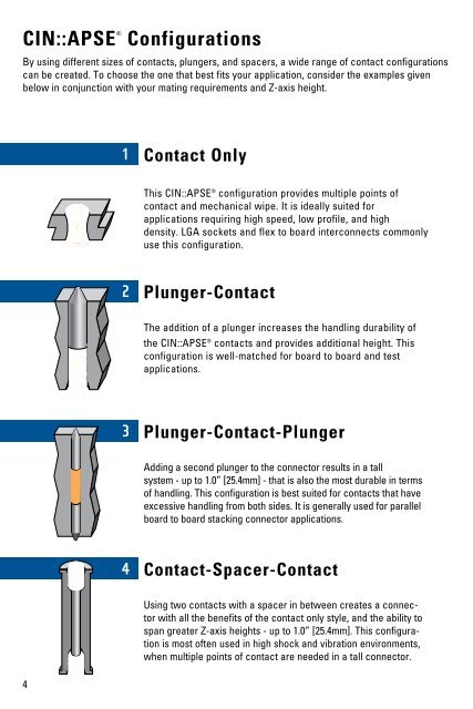
Contact Only<br />
This <strong>CIN</strong>::<strong>APSE</strong> ® configuration provides multiple points of<br />
contact and mechanical wipe. It is ideally suited for<br />
applications requiring high speed, low profile, and high<br />
density. LGA sockets and flex to board interconnects commonly<br />
use this configuration.<br />
Plunger-Contact<br />
The addition of a plunger increases the handling durability of<br />
the <strong>CIN</strong>::<strong>APSE</strong> ® contacts and provides additional height. This<br />
configuration is well-matched for board to board and test<br />
applications.<br />
Plunger-Contact-Plunger<br />
Adding a second plunger to the connector results in a tall<br />
system - up to 1.0” [25.4mm] - that is also the most durable in terms<br />
of handling. This configuration is best suited for contacts that have<br />
excessive handling from both sides. It is generally used for parallel<br />
board to board stacking connector applications.<br />
Contact-Spacer-Contact<br />
Using two contacts with a spacer in between creates a connector<br />
with all the benefits of the contact only style, and the ability to<br />
span greater Z-axis heights - up to 1.0” [25.4mm]. This configuration<br />
is most often used in high shock and vibration environments,<br />
when multiple points of contact are needed in a tall connector.