Nexans Superconducting cable systems
Nexans Superconducting cable systems
Nexans Superconducting cable systems

Create successful ePaper yourself
Turn your PDF publications into a flip-book with our unique Google optimized e-Paper software.
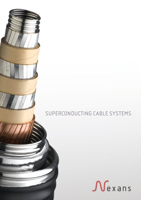
SUPERCONDUCTING CABLE SYSTEMS
INTRODUCTION<br />
An aging and inadequate power<br />
grid is widely seen as one of the<br />
greatest obstacles to the restructuring<br />
of power markets in the United<br />
States, Europe and elsewhere.<br />
Utilities face several converging<br />
pressures: steady load growth,<br />
unplanned additions of new<br />
generation capacity, rising reliability<br />
requirements, sharp price volatility<br />
resulting from new competitive<br />
forces and stringent barriers to siting<br />
SUPERCONDUCTIVITY<br />
In 1911 the Dutch physicist Heike<br />
Kamerlingh Onnes (1853 – 1926)<br />
discovered that the resistance of<br />
mercury, cooled with liquid helium,<br />
falls to zero for temperatures at<br />
4.15 K or below. He called this<br />
effect, which he found also in other<br />
metals, superconductivity.<br />
In superconducting materials, the<br />
superconducting state exists as long<br />
as temperature T, current I, and magnetic<br />
field B are below their critical<br />
values T c , I c and B c .<br />
Since 1911, plenty of superconducting<br />
materials have been<br />
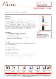
YBCO<br />
buffer layers<br />
substrate<br />
YBCO: YBa 2 Cu 3 O 7 (Y-123)<br />
new facilities, particularly extra high<br />
voltage equipment.<br />
Proposals for conventional grid<br />
expansion are facing persistent<br />
challenges, just as it is becoming<br />
apparent that industry reform cannot<br />
succeed without renewed grid<br />
investment, new transmission, and<br />
distribution capacity. Consequently,<br />
new technologies that can increase<br />
the electrical capacity and flexibility<br />
discovered. In 1986 Johannes<br />
Georg Bednorz and Karl Alexander<br />
Müller discovered the first ceramic<br />
superconductor (La 1.85 Ba 0.15 CuO 4 )<br />
with a critical temperature of 35 K.<br />
Ceramic superconducting materials,<br />
which can be cooled with the less<br />
expensive and commonly available<br />
liquid nitrogen instead of the<br />
expensive liquid helium, were found<br />
in 1987.<br />
HTS <strong>cable</strong>s use tapes or wires<br />
made of superconducting materials<br />
as current carrying elements.<br />
Bi 2 Sr 2 Ca 2 Cu 3 O 10 (BSCCO) with a<br />
critical temperature of 110 K and<br />
YBa 2 Cu 3 O 7 (YBCO) with a critical<br />
coated conductor with multilayer<br />
structure<br />
current densities approaching<br />
100 A/mm² at 77 K in tape<br />
lengths of hundreds of meters<br />
current densities and available<br />
tape length rapidly improving<br />
inherently better<br />
price/performance ratio than<br />
BSCCO<br />
number of buffer layers and<br />
materials depend on manufacturer<br />
of this vital network attract increased<br />
attention.<br />
One of the technologies with<br />
the greatest promise to address<br />
these concerns is the high<br />
capacity underground High-<br />
Temperature Superconductor (HTS)<br />
<strong>cable</strong>. HTS <strong>cable</strong>s are capable<br />
of serving very large power<br />
requirements at medium and high<br />
voltage ratings.<br />
temperature of 92 K are commercially<br />
available superconductors<br />
used in HTS <strong>cable</strong>s.<br />
In 2001 the superconducting<br />
material magnesium diboride<br />
(MgB 2 ) was found with a critical<br />
temperature of 39 K. For superconducting<br />
<strong>cable</strong>s operated at<br />
lower temperatures MgB 2 is used<br />
alternatively. MgB 2 is commercially<br />
available; its good performance<br />
/ costs ratio makes it very<br />
attractive for high current applications.<br />
BSCCO: Bi Sr Ca Cu O 2 2 2 3 10<br />
(Bi-2223)<br />
multifilamentary structure in<br />
silver matrix<br />
available in km length<br />
conductor current densities<br />
of 100 A/mm² and above<br />
commonly available at 77 K<br />
MgB2 multifilamentary structure in<br />
matrix<br />
available in km length<br />
current densities of 1000 A/mm²<br />
available at 20 K
In superconducting power <strong>cable</strong>s layer(s) of HTS tapes, which transmit power, are stranded around a (hollow)<br />
former. The HTS tapes are surrounded by high voltage insulating material, commonly referred to as dielectric.<br />
Furthermore, a cryostat insulates the whole <strong>cable</strong> core against ambient temperature. The HTS tapes are usually<br />
cooled with liquid nitrogen, which is pumped through the <strong>cable</strong> cryostat. Consequently, the dielectric itself is also<br />
immersed in liquid nitrogen. Therefore this <strong>cable</strong> is generally called a cold dielectric <strong>cable</strong>.<br />
HVAC POWER CABLE<br />
In a HVAC <strong>cable</strong> design the inner<br />
layers of HTS tapes transmit power<br />
while the outer layers are grounded.<br />
In the outer layers, currents equal in<br />
magnitude but opposite in phase<br />
to the inner layers are induced.<br />
These induced currents completely<br />
eliminate the electromagnetic fields<br />
of the inner layers.<br />
This is one of the key benefits of<br />
the cold dielectric design. The fact<br />
that the electromagnetic field is<br />
contained inside the superconducting<br />
screen also reduces the <strong>cable</strong><br />
inductance significantly, another<br />
important benefit of the <strong>cable</strong>.<br />
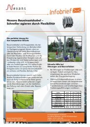
CONCENTRIC MVAC CABLE<br />
For medium voltage applications,<br />
superconducting concentric <strong>cable</strong>s<br />
offer the most compact design with<br />
the best utilization of HTS tapes.<br />
All three phases and a screen, each<br />
separated through dielectrics, are<br />
stranded around a hollow former.<br />
The former can be used as a return<br />
channel for liquid nitrogen.<br />
Compact HTS <strong>cable</strong>s with concentric<br />
design are able to transmit<br />
huge amounts of power in areas<br />
of high population density. Using<br />
the medium voltage level allows a<br />
network architecture, where transformation<br />
substations can be placed<br />
outside urban areas. Due to their<br />
special design, concentric <strong>cable</strong>s,<br />
like HVAC power <strong>cable</strong>s, exhibit no<br />
external magnetic fields.<br />
copper former hollow former HTS phase layers dielectric HTS screen layers copper screen liquid nitrogen<br />
inner cryostat wall super insulation 10 outer cryostat wall 11 PE sheath<br />
10<br />
11<br />
10<br />
11<br />
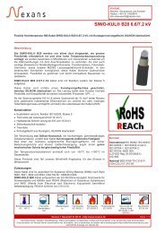
HTS CABLE ARCHITECTURES<br />
HVDC POWER CABLE<br />
The design of superconducting<br />
HVDC power <strong>cable</strong>s is very similar<br />
to the design of superconducting<br />
HVAC power <strong>cable</strong>s. The inner HTS<br />
layers are separated through the<br />
dielectric from a screen, consisting<br />
of copper wires only.<br />
Bipolar HVDC <strong>cable</strong> <strong>systems</strong> enable<br />
the transport of huge amounts of<br />
bulk power. With voltage levels up<br />
to ± 320 kV a transmission power<br />
of 4.5 GW and even more is easily<br />
attainable. In addition, the absence<br />
of charging currents prevents a<br />
limitation of the <strong>cable</strong> length.<br />
10<br />
11
CABLE MANUFACTURING<br />
<strong>Nexans</strong> uses its extensive experience in high voltage <strong>cable</strong>s and<br />
accessories to manufacture superconducting <strong>cable</strong>s using existing industrial<br />
processes. With the same flexibility to meet customer demands for<br />
conventional <strong>cable</strong>s, we have adapted existing stranding machines to comply<br />
with technical demands of the superconducting material.<br />
In cold dielectric <strong>cable</strong>s employing PolyPropylene Laminated Paper (PPLP),<br />
the lapped dielectric is designed to fulfil the demands on dry bending<br />
properties as well as high voltage insulation once impregnated with<br />
liquid nitrogen. Like superconducting tapes the dielectric is stranded on<br />
conventional machines.<br />
For superconducting <strong>cable</strong>s <strong>Nexans</strong> is able to produce the cryogenic<br />
envelope around the <strong>cable</strong> core utilizing the UNIWEMA® technology.<br />
With more than 30 years of experience in cryostat design and manufacturing<br />
a long term high quality vacuum can be ensured to prevent thermal<br />
losses.
Besides the <strong>cable</strong> in the cryostat itself, a superconducting <strong>cable</strong> system<br />
consists of terminations, joints and a cooling system.<br />
HTS CABLE TERMINATIONS<br />
The HTS <strong>cable</strong> terminations as part of the superconducting <strong>cable</strong> system<br />
provide the interface between the <strong>cable</strong> and the rest of the grid. The<br />
superconducting <strong>cable</strong> termination<br />
manages the thermal gradient from cryogenic to ambient temperature<br />
provides electrical field control across the interconnection<br />
connects the superconducting <strong>cable</strong> to the cooling system<br />
compensates the thermal shrinkage of the <strong>cable</strong> during cool down<br />
HTS CABLE JOINT<br />
The HTS <strong>cable</strong> joint<br />
connects several lengths of HTS <strong>cable</strong>s<br />
allows the mass flow of the coolant<br />
provides an electrical and mechanical connection of the <strong>cable</strong> ends<br />
COOLING SYSTEM<br />
The cooling system<br />
cools down the HTS <strong>cable</strong> core<br />
compensates the thermal losses<br />
enables a mass flow of helium gas or liquid nitrogen<br />
SUPERCONDUCTING CABLE SYSTEMS
BENEFITS OF SUPERCONDUCTING CABLES<br />
LOWER VOLTAGES<br />
Because of the higher capacity of<br />
Very Low Impedance <strong>cable</strong>s (VLI)<br />
– approximately three to five times<br />
higher ampacity than conventional<br />
<strong>cable</strong>s – utilities may employ lower<br />
voltage equipment, avoiding both<br />
the electrical (I²R) losses, typical<br />
of high current operation, and the<br />
capital costs of step up and step<br />
down transformers. High current<br />
VLI <strong>cable</strong>s at 115 kV or even 69 kV<br />
may solve problems that would ordinarily<br />
require a 230 kV or 345 kV<br />
conventional solution.<br />
EASIER INSTALLATION<br />
HTS <strong>cable</strong>s are actively cooled<br />
and thermally independent of the<br />
surrounding environment.<br />
LIFE EXTENSION AND<br />
IMPROVED ASSET UTILIZATION<br />
Over time, thermal overload leads<br />
to an aging and degrading of the<br />
<strong>cable</strong> insulation. By drawing flow<br />
away from overtaxed <strong>cable</strong>s and<br />
lines, strategic insertions of VLI<br />
<strong>cable</strong> can “take the heat off” urban<br />
power delivery networks.<br />
REDUCED ELECTRICAL LOSSES<br />
In optimized designs, lower net<br />
energy losses occur in VLI <strong>cable</strong>s<br />
than in either conventional lines<br />
and <strong>cable</strong>s or unshielded HTS<br />
<strong>cable</strong>s with a single conductor per<br />
phase, offering a transmission path<br />
with high electrical efficiency. As<br />
VLI circuits tend to attract power<br />
flow, they will naturally operate at<br />
a high capacity factor, reducing<br />
the losses on other circuits and<br />
further magnifying their efficiency<br />
advantage.<br />
INDIRECT AND NON-MONETARY<br />
SAVINGS<br />
In addition to these investment<br />
cost savings, VLI <strong>cable</strong>s may entail<br />
other advantages. For example,<br />
the time to install may be shortened<br />
because of reduced siting obstacles<br />
associated with compact<br />
underground installations and less<br />
burdensome siting requirements for<br />
lower voltage facilities. VLI <strong>cable</strong>s<br />
might be routed through existing,<br />
retired underground gas, oil or<br />
water pipes, through existing (active<br />
or inactive) electrical conduit, along<br />
highway or railway rights-of-way, or<br />
through other existing corridors.<br />
REDUCED REGIONAL<br />
CONGESTION COSTS<br />
Finally, and perhaps most significantly,<br />
the ability to complete grid<br />
upgrade projects more quickly will<br />
translate into the earlier elimination<br />
or relaxation of grid bottlenecks.<br />
Solving physical bottleneck problems<br />
will sharply reduce the grid<br />
congestion costs that, in today‘s<br />
unsettled, imperfectly competitive<br />
marketplace, can impose huge<br />
penalties on consumers and the<br />
economy at large.<br />
UNDERGROUND INSTALLATION<br />
The underground installation of VLI<br />
<strong>cable</strong>s eliminates the visual impact<br />
of overhead lines.<br />
ENVIRONMENT-FRIENDLY<br />
DIELECTRIC<br />
Liquid nitrogen as coolant is inexpensive,<br />
abundant and environmentally<br />
harmless.<br />
ELIMINATION OF<br />
ELECTROMAGNETIC FIELDS<br />
The coaxial design of VLI cold<br />
dielectric <strong>cable</strong>s completely<br />
suppresses electromagnetic fields.
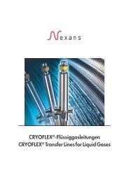
<strong>Nexans</strong> tests superconducting<br />
power <strong>cable</strong> <strong>systems</strong> and their<br />
accessories in their one of a kind<br />
test field in Hannover, Germany.<br />
Combining state-of-the-art high<br />
voltage and cryogenic equipment,<br />
the test field is suitable for superconducting<br />
power <strong>cable</strong>s and<br />
other superconducting high voltage<br />
applications like fault current limiters.<br />
A 30 m x 12 m x 9 m screened cabin<br />
provides ample space to install and<br />
test superconducting power <strong>cable</strong>s<br />
and their accessories. The <strong>cable</strong><br />
system is connected to a cooling<br />
system outside the cabin.<br />
Test field in Hannover, Germany<br />
Test Equipment Data<br />
350 kV,<br />
AC voltage<br />
700 kVA<br />
DC voltage 650 kV<br />
Impulse voltage<br />
AC current 4 kA<br />
1.200 kV,<br />
60 k J<br />
DC current 10 kA<br />
Liquid nitrogen is circulated<br />
through the <strong>cable</strong> loop and a heat<br />
exchanger, which allows adjustment<br />
of the liquid nitrogen temperature<br />
over a wide range. In combination<br />
with variable flow rates, the complete<br />
spectrum of operating conditions<br />
of superconducting power <strong>cable</strong>s<br />
can be evaluated and verified.<br />
Gaseous nitrogen is used to cool<br />
down and warm up test objects.<br />
An automated temperature control<br />
system can provide a constant<br />
temperature gradient during cool<br />
down and warm up.<br />
Cooling System Data<br />
Temperature 65 to 80 K<br />
Mass flow<br />
Cooling system<br />
100 to<br />
2250 g /s<br />
Pressure up to 15 bars<br />
All relevant test data is recorded<br />
by a computer based measurement<br />
system that records temperatures,<br />
pressures, voltages, and currents<br />
during cooling down and the tests.<br />
Making use of a high voltage<br />
transformer, the <strong>cable</strong> dielectric<br />
is evaluated by measuring partial<br />
discharges, loss angle and <strong>cable</strong><br />
capacitances.<br />
Feel free to contact us:<br />
superconductors@nexans.com<br />
TEST FIELD<br />
Services:<br />
high voltage tests<br />
high current tests<br />
network simulations<br />
feasibility studies
<strong>Nexans</strong> Deutschland GmbH · <strong>Superconducting</strong> Cable Systems<br />
Kabelkamp 20 · 30179 Hannover, Germany<br />
Phone + 49 511 676 3226 · Fax + 49 511 676 3010<br />
superconductors@nexans.com · www.nexans.de